EP1555508A1 - Système de mesure - Google Patents
Système de mesure Download PDFInfo
- Publication number
- EP1555508A1 EP1555508A1 EP05000739A EP05000739A EP1555508A1 EP 1555508 A1 EP1555508 A1 EP 1555508A1 EP 05000739 A EP05000739 A EP 05000739A EP 05000739 A EP05000739 A EP 05000739A EP 1555508 A1 EP1555508 A1 EP 1555508A1
- Authority
- EP
- European Patent Office
- Prior art keywords
- light receiving
- manipulator
- target
- receiving device
- robot
- Prior art date
- Legal status (The legal status is an assumption and is not a legal conclusion. Google has not performed a legal analysis and makes no representation as to the accuracy of the status listed.)
- Granted
Links
Images


Classifications
-
- G—PHYSICS
- G01—MEASURING; TESTING
- G01B—MEASURING LENGTH, THICKNESS OR SIMILAR LINEAR DIMENSIONS; MEASURING ANGLES; MEASURING AREAS; MEASURING IRREGULARITIES OF SURFACES OR CONTOURS
- G01B21/00—Measuring arrangements or details thereof, where the measuring technique is not covered by the other groups of this subclass, unspecified or not relevant
- G01B21/02—Measuring arrangements or details thereof, where the measuring technique is not covered by the other groups of this subclass, unspecified or not relevant for measuring length, width, or thickness
- G01B21/04—Measuring arrangements or details thereof, where the measuring technique is not covered by the other groups of this subclass, unspecified or not relevant for measuring length, width, or thickness by measuring coordinates of points
- G01B21/042—Calibration or calibration artifacts
-
- B—PERFORMING OPERATIONS; TRANSPORTING
- B25—HAND TOOLS; PORTABLE POWER-DRIVEN TOOLS; MANIPULATORS
- B25J—MANIPULATORS; CHAMBERS PROVIDED WITH MANIPULATION DEVICES
- B25J19/00—Accessories fitted to manipulators, e.g. for monitoring, for viewing; Safety devices combined with or specially adapted for use in connection with manipulators
- B25J19/02—Sensing devices
- B25J19/021—Optical sensing devices
- B25J19/023—Optical sensing devices including video camera means
-
- G—PHYSICS
- G01—MEASURING; TESTING
- G01B—MEASURING LENGTH, THICKNESS OR SIMILAR LINEAR DIMENSIONS; MEASURING ANGLES; MEASURING AREAS; MEASURING IRREGULARITIES OF SURFACES OR CONTOURS
- G01B11/00—Measuring arrangements characterised by the use of optical techniques
- G01B11/002—Measuring arrangements characterised by the use of optical techniques for measuring two or more coordinates
- G01B11/005—Measuring arrangements characterised by the use of optical techniques for measuring two or more coordinates coordinate measuring machines
-
- G—PHYSICS
- G05—CONTROLLING; REGULATING
- G05B—CONTROL OR REGULATING SYSTEMS IN GENERAL; FUNCTIONAL ELEMENTS OF SUCH SYSTEMS; MONITORING OR TESTING ARRANGEMENTS FOR SUCH SYSTEMS OR ELEMENTS
- G05B2219/00—Program-control systems
- G05B2219/30—Nc systems
- G05B2219/37—Measurements
- G05B2219/37555—Camera detects orientation, position workpiece, points of workpiece
Definitions
- the present invention relates to a measuring system and a method for measuring a position of a target (a point on an object to be measured) by receiving light on a light-receiving surface of a light-receiving device mounted to a robot.
- a touchup method is known as a method for determining a position of an object near a robot and, in particular, a position of a target on the object to be measured.
- This method includes steps of: predetermining a position of a tool center point (TCP) with respect to a coordinate system fixed to an end of an arm of the robot (mechanical interface coordinate system), moving the robot in manual mode such as jog feed so as to accurately coincide TCP with the target (point to be measured), getting position data of the robot so as to determine the position of the target.
- TCP tool center point
- Another method is also known in which a robot and a camera are combined.
- the camera is attached to the end of the arm of the robot.
- the camera is moved by the robot for stereo view measurement, whereby the position of the target relative to the robot is found.
- this method requires a calibration in which a sensor coordinate system generally fixed to a body of the camera is determined and, a position of the sensor coordinate system and a position on an image of the camera corresponding to the position of the sensor coordinate system are calculated.
- a detailed explanation of this calibration is omitted since the calibration is well-known in the art.
- a visual line directed from the camera to the target can be calculated. Therefore, by moving the camera to two positions and measuring the target, a three-dimensional position of the target relative to the robot can be calculated as an intersection point of two visual lines.
- the method in which the camera is attached to the end of the arm of the robot and is moved by the robot for stereo view measurement is based on measurement of the target by the camera. Therefore, the precision level of the method is stable by eliminating a factor including a human error such as visual inspection and the security of the method is high because the method uses non-contact type measurement.
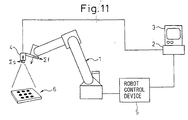
- the combination of the coordinate systems in the calibration is required and, the effort of operation required for the calibration and its preparations is by no means small. The reason for this will be briefly explained with referring to Fig. 11.
- Fig. 11 shows a typically arrangement used for the calibration of prior art.
- a robot denoted by numeral 1 is controlled by a robot control device 5.
- a camera 4 is attached to around the end of the arm of the robot 1.
- the camera 4 is connected to an image processing unit 2 including a monitor 3 having a LCD or a CRT.
- Numeral 6 denotes a fixture shaped like a plate prepared for the calibration or a calibration plate.
- the calibration plate 6 has a dot pattern including a known array of dots.
- the image of the calibration plate is taken by the camera 4 and is analyzed by the image processing unit 2.
- the sensor coordinate system is determined and, parameters indicating the position of the sensor coordinate system and the position on the image of the camera corresponding to the position of the coordinate system are calculated as calibration data and are stored.
- a light receiving part for example, CCD array
- an imaging lens of the camera may have a geometric distortion.
- a lens often has a significant distortion. The distortion of the lens is larger at the perimeter of the lens, therefore, calculation of the visual line from a focal point of the lens to the target may include a small or a large error, depending on the position of the target on the,image.
- an object of the present invention is to provide a measuring system for measuring the target using the camera or an alternative PSD (position sensitive detector) mounted around the end of a manipulator or the robot arm and to carry out measurement without the complicated preparations and the exclusive calibration plate. Also, the invention tends not to be influenced by the geometric distortion of the lens or the light receiving device for imaging.
- PSD position sensitive detector
- the basic characteristic of the invention is to determine the positional relation between the manipulator and the visual line of the camera, by combining following operations; receiving the image of the target on the light receiving surface of the light receiving device (typically the camera or the PSD) attached to around the end of the manipulator, moving the manipulator so as to position the image of the target at a predetermined position (for example, the center of the image of the camera or an origin of the PSD), determining the position of the manipulator and, moving the manipulator so as to change the orientation of the light receiving device.
- a three-dimensional position of the target may be calculated by imaging the target from two points using the light receiving device, based on a principle of stereo measurement.
- a measuring system for measuring a position of a target to be measured relative to a robot having a manipulator
- the measuring system comprising: a light receiving device mounted to the manipulator; a control device for positioning the manipulator to an initial position; and an image processing unit for calculating a position of the target on a light receiving surface of the light receiving device imaged on the light receiving surface;
- the control device comprising: a first arithmetic part for calculating a distance of movement of the manipulator, by means of which the position of the target on the light receiving surface calculated by the image processing unit coincides with a predetermined reference point on the light receiving surface; a drive control part for moving the manipulator according to the distance of movement; a second arithmetic part for calculating a position and an orientation of a visual line of the light receiving device relative to a robot coordinate, based on position data of the manipulator with respect to a plurality of the initial position; and a third arithmetic part for calculating a three
- the reference point on the light receiving surface is positioned generally at a center of the light receiving surface.
- the measuring system may be further include a judgment part for judging, after movement of the manipulator and before storing of the position of the manipulator, that the position of the target imaged on the light receiving surface of the light receiving device coincides with the reference point when the distance between them is within a predetermined error range. Therefore, it is ensured that the position of the target on the light receiving surface of the light receiving device coincides with the reference point on the light receiving surface.
- the position of the manipulator after movement may be reset as the initial position when the judgment part judges that the position of the target does not coincide with the reference point on the light receiving surface. Therefore, it is further ensured that the position of the target on the light receiving surface of the light receiving device coincides with the reference point on the light receiving surface, by repeating a movement of the robot.
- the second arithmetic part may calculate the orientation of the visual line of the light receiving device relative to the robot coordinate based on at least two positions of the manipulator, the two positions being determined such that the orientations of the light receiving device at the two positions are same each other and the distances between the light receiving device and the target at the two positions are different with each other. Therefore, there is provided an embodiment for calculating the orientation of the visual line of the light receiving device relative to the robot.
- the second arithmetic part may calculate the position of the visual line of the light receiving device relative to the robot coordinate based on the orientation of the visual line and at least two positions of the manipulator, the two positions being determined by changing the orientation of the light receiving device by a motion including a rotation about an axis parallel to the orientation of the visual line. Therefore, there is provided an embodiment for calculating the position of the visual line of the light receiving device relative to the robot.
- the third arithmetic part may calculate the three-dimensional position of the target relative to the robot coordinate based on the orientation and the position of the visual line and at least two positions of the manipulator, the two positions being determined by changing the orientation of the light receiving device by a motion including a rotation about an axis perpendicular to the orientation of the visual line. Therefore, there is provided an embodiment for calculating the three-dimensional position of target.
- the light receiving device may be detachably mounted around the end of the manipulator, whereby the light receiving device may be attached around the end of the manipulator when measurement is carried out and may be detached after the measurement.
- the light receiving device may be detachably mounted around the end of the manipulator, whereby the robot may be used for measurement of a position of an object to be measured relative to robot by attaching the light receiving device around the end of the manipulator and, after the measurement, the robot may be used for an application other than the measurement by detaching the light receiving device.
- the light receiving device may be a camera for imaging a two-dimensional image, or a position sensitive detector for calculating a center of gravity of a distribution of a received light.
- a measuring method for measuring a position of a target to be measured relative to a robot having a manipulator comprising: preparing a light receiving device mounted to the manipulator; positioning the manipulator to an initial position; calculating a position of the target on a light receiving surface of the light receiving device imaged on the light receiving surface; calculating a distance of movement of the manipulator, by means of which the position of the target on the light receiving surface coincides with a predetermined reference point on the light receiving surface; moving the manipulator according to the distance of movement; calculating at least one of a position and an orientation of a visual line of the light receiving device relative to a robot coordinate, based on position data of the manipulator with respect to a plurality of the initial position; and calculating a three-dimensional position of the target relative to the robot coordinate, based on at least one of the position and the orientation of the visual line.
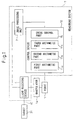
- FIG. 1 is shows a schematic configuration of a measuring system according to the present invention.
- a measuring system 7 for measuring a position of a target 31 to be measured relative to a robot 1 having a manipulator 1a includes a light receiving device 4 mounted to the manipulator 1a, a control device 10 for positioning the manipulator 1a to an initial position; and an image processing unit 2 for calculating a position of the target 31 on a light receiving surface of the light receiving device 4 imaged on the light receiving surface.
- the control device 10 includes a first arithmetic part 11a for calculating a distance of movement of the manipulator 1a, by means of which the position of the target 31 on the light receiving surface calculated by the image processing unit 2 coincides with a predetermined reference point on the light receiving surface, a drive control part 15 for moving the manipulator 1a according to the distance of movement, a second arithmetic part 11b for calculating at least one of a position and an orientation of a visual line 40 of the light receiving device relative to a robot coordinate, and a third arithmetic part 11c for calculating a three-dimensional position of the target 31 relative to the robot coordinate based on at least one of the position and the orientation of the visual line 40.
- a main CPU 11 executes the functions of the first, the second and the third arithmetic part 11a, 11b and 11c.
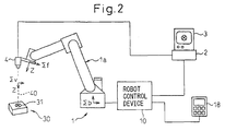
- FIG. 2 shows a total configuration of the embodiment of the invention.
- the light receiving device 4 (for example a camera) is mounted around the end of the manipulator 1a of the robot 1.
- the camera 4 may be a known CCD camera having a function for detecting a two-dimensional image of an object on a light receiving surface or a CCD array surface by imaging.
- the camera 4 is connected to a image processing unit 2 having a monitor 3 such as a LCD or a CRT.
- a numeral 30 denotes an object positioned around the robot 1. The relative position of the object 30 to the robot 1 is to be calculated and a target or a point 31 to be measured therefor is arranged on the object 30.
- the target 31 may be a shape characteristic of the object 30 or a reference mark arranged on the object for measurement. As described later, the target 31 is imaged by the camera 4 and the image of the target 31 is analyzed by the image processing unit 2.
- a visual line denoted by a numeral 40 is determined as a straight line extending from a representative point of the camera 4 (for example, a center of the light receiving surface of the camera) to the target 31 via a focal point of an imaging lens of the camera 4.
- the monitor 3 may be a LCD of a CRT integrated with the image processing unit 2 and, may indicate a desired image at need.
- the robot 1 may be a conventional typical robot and has a robot control device 10 having a block configuration as shown in Fig. 3.
- the robot control device 10 has a main CPU (a main central processing unit; hereinafter, simply referred to as a CPU) 11, a storage or a memory 12 consisting of a RAM (random access memory), a ROM (read-only memory) and a non-volatile memory, a teaching board interface 13, a communication interface 14, a drive control part of a servo control unit 15 and an input/output interface 16 for external units, which are connected each other in parallel via a bus 17.
- a main CPU a main central processing unit; hereinafter, simply referred to as a CPU
- a storage or a memory 12 consisting of a RAM (random access memory), a ROM (read-only memory) and a non-volatile memory
- teaching board interface 13 a communication interface 14
- drive control part of a servo control unit 15 and an input/output interface 16 for external units
- a teaching board 18 connected to the teaching board interface 13 may have the usual display functions.
- An operator prepares, corrects, and registers a motion program for the robot by manually operating the teaching board 18.
- the operator also sets various parameters, operates the robot based on the taught motion program, and jog feeds, in the manual mode.
- a system program that supports the basic function of the robot 1 and the robot control device 10 is stored in the ROM of the memory 12.
- the motion program (for example, a spot welding) of the robot taught according to the application and relevant set data are stored in the non-volatile memory of the memory 12.
- a program and parameters used to carry out processes are also stored in the non-volatile memory of the memory 12.
- the RAM of the memory 12 is used for a storage area to temporarily store various data processed by the CPU 11.
- the servo control unit 15 has servo controllers #1 to #n, where n is a total number of axes of the robot, and n is assumed to be equal to 6 in this case.
- the servo control unit 15 receives a shift command prepared through operations (such as a path plan preparation, and interpolation and an inverse transformation based on the plan) to control the robot.
- the servo control unit 15 outputs torque commands to servo amplifiers A1 to An based on the shift command and feedback signals received from pulse coders not shown belonging to the axes.
- the servo amplifiers A1 to An supply currents to servomotors of the respective axes based on the torque commands, thereby driving the servomotors.
- the communication interface 14 is connected to the image processing unit 2 shown in Fig. 2.
- the robot control device 10 exchanges commands relevant to measurement and measured data described later with the image processing unit 2 via the communication interface 14.
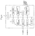
- the image processing unit 2 has a block configuration as shown in Fig. 4.
- the image processing unit 2 has a CPU 20 including a microprocessor, and also has a ROM 21, an image processor 22, a camera interface 23, a monitor interface 24, an input/output (I/O) unit 25, a frame memory (i.e., an image memory) 26, a non-volatile memory 27, a RAM 28 and a communication interface 29, that are connected to the CPU 20 via a bus line 32.
- a CPU 20 including a microprocessor, and also has a ROM 21, an image processor 22, a camera interface 23, a monitor interface 24, an input/output (I/O) unit 25, a frame memory (i.e., an image memory) 26, a non-volatile memory 27, a RAM 28 and a communication interface 29, that are connected to the CPU 20 via a bus line 32.
- I/O input/output
- a camera as an imaging unit which is the camera 4 shown in Fig. 2 in this case, is connected to the camera interface 23.
- the camera receives an imaging command via the camera interface 23
- the camera picks up an image using an electronic shutter function incorporated in the camera.
- the camera sends a picked-up video signal to the frame memory 26 via the camera interface 23, and the frame memory 26 stores the video signal in the form of a grayscale signal.
- a monitor which is the monitor 3 shown in Fig. 2 in this case, is connected to the monitor interface 24.
- the monitor displays images currently picked up by the camera, past images stored in the frame memory 26, or images processed by the image processor 22, according to need.
- the image processor 22 analyses the video signal of the image of the target 31 stored in the frame memory 26 and, a three-dimensional position of the target is obtained, as described later in detail.
- a program and parameters for this purpose are stored in the non-volatile memory 27.
- the RAM 28 temporarily stores data that the CPU 20 uses to execute various processing.
- the communication interface 29 is connected to the robot control device via the communication interface 14 at the robot control device side.
- ⁇ v indicates a coordinate system including a visual line 40 extending from a representative point (for example a center of the light receiving surface) of the camera 4 to the target 31 via the focal point of the imaging lens of the camera 4.
- the origin of the coordinate system ⁇ v is positioned on the visual line 40 and one axis of the coordinate system (for example, Z axis) coincides with the visual line 40.
- a coordinate system associated with the base of the robot and a mechanical interface coordinate system are indicated by ⁇ b and ⁇ f, respectively.
- the mechanical interface coordinate system ⁇ f is determined as a coordinate system including a representative point of the manipulator. The three-dimensional position of the target 31 relative to the coordinate system ⁇ f is calculated, as described below.
- the calculated three-dimensional position may be converted into a three-positional position relative to the robot coordinate system ⁇ b, based on the positional relation between the coordinate systems ⁇ b and ⁇ f, i.e., using a known coordinate transformation method.
- the light receiving device in the embodiment of the invention is described as the CCD camera for imaging a two-dimensional image of the object, the light receiving device may be another device such as a CMOS camera having substantially same functions as the CCD, otherwise, may be a position sensitive detector (PSD) for calculating a (two-dimensional) position of a center of gravity of a distribution of received light when the target 31 may be considered as a point light source.
- PSD position sensitive detector
- the image processing unit 2 is replaced with another unit being adapted to the alternative device.
- a processing unit having a function for calculating the (two-dimensional) position of the center of gravity of the distribution of received light by processing an output signal from the PSD is used.
- the light receiving device is the (CCD) camera connected to the image processing unit 2
- the camera and the image processing unit may be replaced other light receiving device and signal processing unit, respectively, as described above.
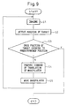
- the entire process executed in the embodiment is shown in a flowchart of Fig. 10 and now will be described with reference to the flowchart.
- the position of the target 31 on the light receiving surface of the light receiving device is moved to a predetermined point or a reference point on the light receiving surface in order to obtain data of the visual line 40 without using a calibration of prior art.
- step T1 the manipulator 1a of the robot 1 is moved to an initial position where the visual field of the camera 4 includes the image of the target 31.
- step T2 a moving process to a predetermined position or a reference position is executed.
- the light receiving device is moved such that the position of the target 31 on the light receiving surface is moved and coincides with the reference point (or come to a point where the distance between the point and the reference point is within a predetermined range).
- the reference point is a center point of the light receiving surface (or a CCD array).
- Fig 5 shows movement of the image the target 31 to the center point of the light receiving surface using a display of the monitor 3.
- the display of the monitor 3 is configured such that a center M of the display corresponds to the center of the light receiving device of the camera 4.
- the manipulator 1a should be moved such that the image 31a on the display is moved to lower-left toward a point M.
- the direction along which the manipulator 1a should be moved cannot be determined based on the position of the target on the display. Therefore, it must be previously determined how the manipulator 1a should be moved so as to move the image 31a of the target 31 to a desired point (or the point M in this case).
- the manipulator is moved in three directions (i.e.; X, Y and Z axes) of the mechanical interface coordinate system ⁇ f in Fig. 2 and, the movement of the image 31a of the target 31 corresponding to the movement of the manipulator is observed, whereby the relation between the direction of the movement of the manipulator 1a and the direction of the movement of the image of the target on the display and, the relation between the distance of the movement of the manipulator 1a and the distance of the movement of the image of the target on the display may be determined. If this procedure is executed after the camera 4 is mounted or fixed around the end of the manipulator 1a, it is not necessary to execute the procedure afterward.
- the target 31 to be measured is imaged, whereby the image 31a as shown in Fig. 5 is obtained.
- the image processing unit 2 calculates the position of the target 31 (or the position of the image 31a) on the display.
- the main CPU 11 or a suitable judgment part judges whether the position calculated in step S2 coincides with a predetermined point (the point M in this case) or not. For example, if the distance between the point M and the image 31a on the display is equal to or smaller than a predetermined threshold ( ⁇ image), the CPU 11 judges this situation as "coincidence” and the process is stopped. Contrarily, if the distance is larger than the threshold ( ⁇ image), the CPU 11 judges as "discordance" and the process is progressed to step S4.
- the distance on the display may be calculated, for example, by counting a number of square picture elements.
- a command of translation of robot for moving the image 31a of the target on the display to the point M is prepared.
- the command of translation means a command of movement for moving the manipulator such that the orientation of the manipulator or the orientation of the coordinate system ⁇ f is fixed relative to the robot coordinate system ⁇ b.
- the manipulator 1a is moved based on the command of translation prepared in step S4.
- the process is returned to step S1 after the movement of the manipulator.
- a cycle of steps described above is repeated until the judgment by the CPU 11 become "coincide" in step S2.
- the visual line 40 is a straight line extending from the point M on the receiving surface of the camera corresponding to the center of the display to target 31 to be measured via the center point of the imaging lens.
- the direction of the straight line relative to the coordinate system ⁇ f representing the mechanical interface of the robot is calculated.
- the manipulator 1a is translated by a process of step T4.
- FIG. 6 is an explanatory diagram regarding the process.
- a coordinate system ⁇ v1 is set for calculating the orientation of the visual line 40 and satisfies following conditions:
- the direction of Z-axis of the coordinate ⁇ v1 on the coordinate system ⁇ f is calculated when the process for movement to the reference point is completed.
- (W, P) components of an Euler angle (W, P, R) representing the orientation of the coordinate system ⁇ v1 on the coordinate system ⁇ f are calculated.
- step T4 the translation according to step T4 is executed.
- the manipulator 1a positioned at a first position is moved, without changing the orientation of the camera, to a second position where the distance between the camera and the target 31 is different to that at the first position (see an arrow A in Fig. 6).
- Numerals 4a and 4b in Fig. 6 indicate the camera before translation and after translation, respectively.
- step T4 After the translation in step T4, in general, the image of the target 31 is deviated from the center point M of the display (or the center point of the light receiving surface). Therefore, the above process for movement to the reference point as described regarding step T2 is executed again (step T5), whereby the image of the target 31 coincides with the point M again.
- step T5 When the step T5 is completed, a position Qf2 of the coordinate system ⁇ f relative to the robot coordinate system ⁇ b is obtained and stored (step T6).
- the orientation of the visual line 40 is represented by a straight line extending from the position Qf1 calculated in step T3 to the position Qf2 calculated in step T6.
- the coordinate system ⁇ v1 may be calculated by the above equations and, the orientation of the visual line 40 coincides with the direction of Z-axis of the coordinate system.
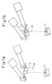
- Figs. 7a and 7b are explanatory diagrams regarding the steps.
- a coordinate system ⁇ v2 corresponding ⁇ v shown in Fig. 2 represents the position and the orientation of the visual line 40 and satisfies following conditions:
- the orientation of the visual line 40 has already calculated as the direction of Z-axis of the coordinate system ⁇ v1 (see Fig. 7a) and, the direction of Z-axis of the coordinate system ⁇ v2 coincides with the direction of Z-axis of the coordinate system ⁇ v1.
- the manipulator is moved such that the position Qf1 is rotated by 180 degree about Z-axis of the coordinate system ⁇ v1 (step T8), then, the above process for movement to the reference point is executed again (step T9).
- Fig. 7a shows a condition in which this rotation (see an arrow B) and the process for movement to the reference point are completed
- Fig. 7b shows the position of the origin of the coordinate system ⁇ v2.
- the position of the origin of the coordinate system ⁇ v2 is determined as a middle point of the points of the coordinate system ⁇ f before and after the rotation.
- the position Qf3 of the coordinate system ⁇ f is obtained and stored (step T10).
- the origin of the coordinate system ⁇ v2 is determined as a middle point of the positions Qf1 and Qf3.
- the orientation and position of the coordinate system ⁇ v2 relative to the coordinate system ⁇ f before the movement of the manipulator in step T8 may be calculated (step T11).
- a matrix for calculating the orientation and position of the coordinate system ⁇ v2 is denoted by [V].
- Fig. 8 is an explanatory diagram regarding the steps.
- the manipulator is inclined or moved such that the position Qf1 is rotated about Y-axis of the coordinate system ⁇ v2 (step T12).
- the above process for movement to the reference point is executed (step T13).
- a position where the inclination is completed is indicated with the visual line 40b.
- the coordinate system ⁇ v2 is moved to ⁇ v2'.
- the visual line before the inclination is denoted by a numeral 40a.
- a position Qf4 of the manipulator is obtained and stored (step T14).
- the visual line relative to the coordinate system ⁇ f may be calculated by the matrix [V] when the manipulator is positioned at the position Qf1.
- the visual line may be represented as below: Qf1 -1 ⁇ Qf4 ⁇ [V]
- a suitable third arithmetic part of the main CPU 11 calculates a position of an intersection point of Z-axes of the coordinates ⁇ v2 and ⁇ v2' so as to determine the three-dimensional position of the target 31 (step T15).
- the visual line extending from the camera to the target may be easily obtained without calibration using an exclusive calibration plate of prior art.
- a geometric distortion of the light receiving device or a lens of the camera does not influence the measurement by calculating the position of the target based on data obtained when the image of the target is positioned at a predetermined position of the display.
- the measurement may be executed with high precision in a simple way.
- a condition ready for measurement may be easily reconstructed even if the positional relation between the camera and the robot is changed such that the measurement cannot be carried out.
- a measuring system in which the camera may be attached to the end of the manipulator at need and may be detached after the measurement may be constructed. It is advantageous that the robot may be used as one component of the measuring system only when the measurement is carried out and may be used for other applications in other time.
Landscapes
- Engineering & Computer Science (AREA)
- Physics & Mathematics (AREA)
- General Physics & Mathematics (AREA)
- Multimedia (AREA)
- Robotics (AREA)
- Mechanical Engineering (AREA)
- Length Measuring Devices By Optical Means (AREA)
- Manipulator (AREA)
Applications Claiming Priority (2)
| Application Number | Priority Date | Filing Date | Title |
|---|---|---|---|
| JP2004009848 | 2004-01-16 | ||
| JP2004009848A JP4021413B2 (ja) | 2004-01-16 | 2004-01-16 | 計測装置 |
Publications (2)
| Publication Number | Publication Date |
|---|---|
| EP1555508A1 true EP1555508A1 (fr) | 2005-07-20 |
| EP1555508B1 EP1555508B1 (fr) | 2007-11-07 |
Family
ID=34616926
Family Applications (1)
| Application Number | Title | Priority Date | Filing Date |
|---|---|---|---|
| EP05000739A Active EP1555508B1 (fr) | 2004-01-16 | 2005-01-14 | Système de mesure |
Country Status (4)
| Country | Link |
|---|---|
| US (1) | US7532949B2 (fr) |
| EP (1) | EP1555508B1 (fr) |
| JP (1) | JP4021413B2 (fr) |
| DE (1) | DE602005003147T2 (fr) |
Cited By (10)
| Publication number | Priority date | Publication date | Assignee | Title |
|---|---|---|---|---|
| EP1621297A1 (fr) * | 2004-07-28 | 2006-02-01 | Fanuc Ltd | Méthode pour recalibrer un capteur optique 3D dans un système robotique |
| DE102006003555A1 (de) * | 2006-01-25 | 2007-07-26 | Edag Engineering + Design Ag | Steuerung für eine Werkzeug-Sensor-Vorrichtung |
| EP1875991A2 (fr) | 2006-07-03 | 2008-01-09 | Fanuc Ltd | Système de mesure et procédé d'étalonnage |
| RU2456542C2 (ru) * | 2010-05-12 | 2012-07-20 | Федеральное государственное бюджетное образовательное учреждение высшего профессионального образования "Санкт-Петербургский национальный исследовательский университет информационных технологий, механики и оптики" (НИУ ИТМО) | Способ измерения линейного смещения объекта и устройство для его осуществления |
| WO2012142587A1 (fr) * | 2011-04-15 | 2012-10-18 | Irobot Corporation | Procédé et système de recherche automatique pour un véhicule télécommandé |
| CN104019743A (zh) * | 2014-06-06 | 2014-09-03 | 清华大学深圳研究生院 | 机械手位姿精度测试系统 |
| EP2767370A3 (fr) * | 2013-02-14 | 2014-12-17 | Canon Kabushiki Kaisha | Système de robot et son procédé de contrôle |
| CN106767517A (zh) * | 2017-01-18 | 2017-05-31 | 重庆市计量质量检测研究院 | 一种自由曲面内三维缝隙形貌自动采集方法及采集装置 |
| CN107917666A (zh) * | 2016-10-09 | 2018-04-17 | 上海铼钠克数控科技股份有限公司 | 双目视觉装置及坐标标定方法 |
| US11338440B2 (en) | 2018-07-30 | 2022-05-24 | Fanuc Corporation | Robot system and calibration method |
Families Citing this family (62)
| Publication number | Priority date | Publication date | Assignee | Title |
|---|---|---|---|---|
| JP4137909B2 (ja) * | 2005-04-13 | 2008-08-20 | ファナック株式会社 | ロボットプログラム補正装置 |
| JP4595042B2 (ja) * | 2005-09-30 | 2010-12-08 | コニカミノルタセンシング株式会社 | 3次元測定方法およびシステム並びにマニピュレータの制御方法および装置 |
| JP4298757B2 (ja) | 2007-02-05 | 2009-07-22 | ファナック株式会社 | ロボット機構のキャリブレーション装置及び方法 |
| DE102007033486B4 (de) * | 2007-07-18 | 2010-06-17 | Metaio Gmbh | Verfahren und System zur Vermischung eines virtuellen Datenmodells mit einem von einer Kamera oder einer Darstellungsvorrichtung generierten Abbild |
| GB0809037D0 (en) | 2008-05-19 | 2008-06-25 | Renishaw Plc | Video Probe |
| JP5113623B2 (ja) * | 2008-05-20 | 2013-01-09 | ファナック株式会社 | 計測装置を用いてロボットの位置教示を行うロボット制御装置 |
| DE102008042261B4 (de) * | 2008-09-22 | 2018-11-15 | Robert Bosch Gmbh | Verfahren zur flexiblen Handhabung von Objekten mit einem Handhabungsgerät und eine Anordnung für ein Handhabungsgerät |
| DE102008042260B4 (de) * | 2008-09-22 | 2018-11-15 | Robert Bosch Gmbh | Verfahren zur flexiblen Handhabung von Objekten mit einem Handhabungsgerät und eine Anordnung für ein Handhabungsgerät |
| JP2010139329A (ja) | 2008-12-10 | 2010-06-24 | Fanuc Ltd | キャリブレーション用の校正治具および校正治具を備えた画像計測システム |
| JP2010152550A (ja) | 2008-12-24 | 2010-07-08 | Canon Inc | 作業装置及びその校正方法 |
| US8310539B2 (en) * | 2009-05-29 | 2012-11-13 | Mori Seiki Co., Ltd | Calibration method and calibration device |
| GB0909635D0 (en) * | 2009-06-04 | 2009-07-22 | Renishaw Plc | Vision measurement probe |
| JP4763074B2 (ja) * | 2009-08-03 | 2011-08-31 | ファナック株式会社 | ロボットのツール先端点の位置の計測装置および計測方法 |
| JP2011067889A (ja) * | 2009-09-25 | 2011-04-07 | Ihi Corp | キャリブレーション装置及びキャリブレーション方法 |
| US9393694B2 (en) * | 2010-05-14 | 2016-07-19 | Cognex Corporation | System and method for robust calibration between a machine vision system and a robot |
| JP5494267B2 (ja) * | 2010-06-15 | 2014-05-14 | セイコーエプソン株式会社 | 三次元形状計測装置、三次元形状計測装置のキャリブレーション方法、およびロボット装置 |
| JP5382053B2 (ja) * | 2011-04-15 | 2014-01-08 | 株式会社安川電機 | ロボットシステムおよびロボットシステムを用いた検査方法 |
| JP2012223839A (ja) * | 2011-04-15 | 2012-11-15 | Yaskawa Electric Corp | ロボットシステムおよびロボットシステムの駆動方法 |
| US9188973B2 (en) | 2011-07-08 | 2015-11-17 | Restoration Robotics, Inc. | Calibration and transformation of a camera system's coordinate system |
| US9279661B2 (en) | 2011-07-08 | 2016-03-08 | Canon Kabushiki Kaisha | Information processing apparatus and information processing method |
| US9437005B2 (en) | 2011-07-08 | 2016-09-06 | Canon Kabushiki Kaisha | Information processing apparatus and information processing method |
| CN102501252A (zh) * | 2011-09-28 | 2012-06-20 | 三一重工股份有限公司 | 一种控制执行臂末端运动的方法及控制系统 |
| TW201315577A (zh) * | 2011-10-03 | 2013-04-16 | Hon Hai Prec Ind Co Ltd | 機械手臂運動控制系統及方法 |
| JP6031368B2 (ja) * | 2013-01-31 | 2016-11-24 | 本田技研工業株式会社 | ワークとの相関位置決め方法 |
| CN103195251B (zh) * | 2013-03-28 | 2015-06-10 | 中联重科股份有限公司 | 臂架末端的运动控制方法、装置、系统和多节臂架车辆 |
| JP6468741B2 (ja) * | 2013-07-22 | 2019-02-13 | キヤノン株式会社 | ロボットシステム及びロボットシステムの校正方法 |
| JP6335460B2 (ja) * | 2013-09-26 | 2018-05-30 | キヤノン株式会社 | ロボットシステムの制御装置及び指令値生成方法、並びにロボットシステムの制御方法 |
| JP6361213B2 (ja) * | 2014-03-26 | 2018-07-25 | セイコーエプソン株式会社 | ロボット制御装置、ロボット、ロボットシステム、教示方法、及びプログラム |
| CN104227724B (zh) * | 2014-08-28 | 2017-01-18 | 北京易拓智谱科技有限公司 | 一种基于视觉识别的通用机器人末端位置的操控方法 |
| JP2016070762A (ja) * | 2014-09-29 | 2016-05-09 | ファナック株式会社 | 対象物の三次元位置を検出する検出方法および検出装置 |
| CN104808490B (zh) * | 2015-03-10 | 2017-04-19 | 浙江工业大学 | 一种面向模具保护的无标定视觉伺服控制方法 |
| DE102015104587B4 (de) | 2015-03-26 | 2022-04-28 | Pi4_Robotics Gmbh | Verfahren zum Kalibrieren eines Roboters an einem Arbeitsbereich und System zum Durchführen des Verfahrens |
| CN104808554B (zh) * | 2015-04-20 | 2017-12-01 | 深圳市文鼎创数据科技有限公司 | 一种自动拾卡系统及其拾卡方法 |
| JP2016221645A (ja) * | 2015-06-02 | 2016-12-28 | セイコーエプソン株式会社 | ロボット、ロボット制御装置およびロボットシステム |
| DE102016116702B4 (de) | 2015-09-14 | 2019-01-24 | Fanuc Corporation | Messsystem zum Kalibrieren der mechanischen Parameter eines Roboters |
| JP6126183B2 (ja) | 2015-10-05 | 2017-05-10 | ファナック株式会社 | ターゲットマークを撮像するカメラを備えたロボットシステム |
| JP6710946B2 (ja) * | 2015-12-01 | 2020-06-17 | セイコーエプソン株式会社 | 制御装置、ロボットおよびロボットシステム |
| CN105423921B (zh) * | 2015-12-24 | 2018-03-16 | 吉林大学 | 基于机器视觉的汽车空间特征点位置柔性检测系统 |
| US9815204B2 (en) * | 2016-01-22 | 2017-11-14 | The Boeing Company | Apparatus and method to optically locate workpiece for robotic operations |
| JP6564350B2 (ja) * | 2016-07-12 | 2019-08-21 | ファナック株式会社 | ロボットの不良部品診断装置および方法 |
| TWI614103B (zh) * | 2016-10-21 | 2018-02-11 | 和碩聯合科技股份有限公司 | 機械手臂定位方法及應用其的系統 |
| JP6922204B2 (ja) * | 2016-12-09 | 2021-08-18 | セイコーエプソン株式会社 | 制御装置、ロボットおよびロボットシステム |
| JP6860843B2 (ja) * | 2017-02-20 | 2021-04-21 | 株式会社安川電機 | ロボットシステム、ロボット制御装置、及びロボット制御方法 |
| JP6914515B2 (ja) * | 2017-07-10 | 2021-08-04 | 新明工業株式会社 | トー調整ロボット |
| JP6622765B2 (ja) * | 2017-08-22 | 2019-12-18 | ファナック株式会社 | ロボットシステム |
| JP2019097136A (ja) * | 2017-11-28 | 2019-06-20 | セイコーエプソン株式会社 | ロボット、アナログデジタル変換器、及び、固体撮像装置 |
| JP6888580B2 (ja) * | 2018-04-05 | 2021-06-16 | オムロン株式会社 | 情報処理装置、情報処理方法、及びプログラム |
| CN110823922A (zh) * | 2018-08-10 | 2020-02-21 | 鸿富锦精密电子(天津)有限公司 | 外观检测装置 |
| US10871366B2 (en) | 2018-08-16 | 2020-12-22 | Mitutoyo Corporation | Supplementary metrology position coordinates determination system for use with a robot |
| US10751883B2 (en) * | 2018-08-16 | 2020-08-25 | Mitutoyo Corporation | Robot system with supplementary metrology position coordinates determination system |
| US11002529B2 (en) | 2018-08-16 | 2021-05-11 | Mitutoyo Corporation | Robot system with supplementary metrology position determination system |
| US11745354B2 (en) | 2018-08-16 | 2023-09-05 | Mitutoyo Corporation | Supplementary metrology position coordinates determination system including an alignment sensor for use with a robot |
| US10913156B2 (en) | 2018-09-24 | 2021-02-09 | Mitutoyo Corporation | Robot system with end tool metrology position coordinates determination system |
| KR102561103B1 (ko) * | 2018-11-16 | 2023-07-31 | 삼성전자주식회사 | 로봇 보정 시스템 및 그것의 보정 방법 |
| JP7372513B2 (ja) * | 2018-12-05 | 2023-11-01 | ミツミ電機株式会社 | 撮像デバイス、撮像システム、および産業用ロボット |
| US10369698B1 (en) | 2019-03-07 | 2019-08-06 | Mujin, Inc. | Method and system for performing automatic camera calibration for robot control |
| CN113597362A (zh) * | 2019-03-25 | 2021-11-02 | Abb瑞士股份有限公司 | 用于确定机器人坐标系与可移动装置坐标系之间的关系的方法和控制装置 |
| US11173610B2 (en) * | 2019-11-13 | 2021-11-16 | Vicarious Fpc, Inc. | Method and system for robot control using visual feedback |
| CN110954023A (zh) * | 2019-12-23 | 2020-04-03 | 芜湖哈特机器人产业技术研究院有限公司 | 一种多功能视觉实验台及其工作方法 |
| US20230339117A1 (en) | 2020-04-13 | 2023-10-26 | Fanuc Corporation | Device for obtaining position of visual sensor in control coordinate system of robot, robot system, method, and computer program |
| WO2023067659A1 (fr) | 2021-10-18 | 2023-04-27 | ファナック株式会社 | Dispositif de commande |
| CN116512260B (zh) * | 2023-05-10 | 2023-10-27 | 江苏普达迪泰科技有限公司 | 一种用于相机测量坐标系标定的装置 |
Citations (6)
| Publication number | Priority date | Publication date | Assignee | Title |
|---|---|---|---|---|
| JPH07328971A (ja) * | 1994-06-08 | 1995-12-19 | Toshiba Corp | Tvカメラ付マニピュレータ |
| JPH0847881A (ja) * | 1994-08-05 | 1996-02-20 | Ishikawajima Harima Heavy Ind Co Ltd | ロボットの遠隔操作方法 |
| JPH08272414A (ja) * | 1995-03-29 | 1996-10-18 | Fanuc Ltd | ロボットとハンドカメラを用いた視覚センサのキャリブレーション方法 |
| JPH1049218A (ja) * | 1996-08-07 | 1998-02-20 | Fanuc Ltd | ロボットの位置教示のための移動制御方式 |
| JP2000131060A (ja) * | 1998-10-29 | 2000-05-12 | Mitsubishi Electric Corp | 測量装置及び測量方法 |
| JP2001349707A (ja) * | 2000-06-12 | 2001-12-21 | Asia Air Survey Co Ltd | 移動体の3次元位置計測システム |
Family Cites Families (10)
| Publication number | Priority date | Publication date | Assignee | Title |
|---|---|---|---|---|
| JPH02198791A (ja) | 1989-01-21 | 1990-08-07 | Omron Tateisi Electron Co | 視覚ロボットの座標系校正方法 |
| JPH02194302A (ja) | 1989-01-23 | 1990-07-31 | Omron Tateisi Electron Co | 視覚ロボットの座標系校正方法およびその方法に用いる座標系校正用変位計測装置 |
| JP2698660B2 (ja) * | 1989-06-12 | 1998-01-19 | 株式会社日立製作所 | マニピュレータの制御方法及び制御装置並びにマニピュレータ装置 |
| US5086401A (en) * | 1990-05-11 | 1992-02-04 | International Business Machines Corporation | Image-directed robotic system for precise robotic surgery including redundant consistency checking |
| US5279309A (en) * | 1991-06-13 | 1994-01-18 | International Business Machines Corporation | Signaling device and method for monitoring positions in a surgical operation |
| JPH05277973A (ja) | 1991-12-25 | 1993-10-26 | Sanyo Electric Co Ltd | マニピュレータのキャリブレーション方法 |
| JPH1063317A (ja) | 1996-08-13 | 1998-03-06 | Fanuc Ltd | ロボット−視覚センサシステムにおける座標系結合方法 |
| JPH1080882A (ja) | 1996-09-06 | 1998-03-31 | Fujitsu Ltd | ロボット用座標変換パラメータ測定方法 |
| US5960125A (en) * | 1996-11-21 | 1999-09-28 | Cognex Corporation | Nonfeedback-based machine vision method for determining a calibration relationship between a camera and a moveable object |
| GB9803364D0 (en) * | 1998-02-18 | 1998-04-15 | Armstrong Healthcare Ltd | Improvements in or relating to a method of an apparatus for registering a robot |
-
2004
- 2004-01-16 JP JP2004009848A patent/JP4021413B2/ja not_active Expired - Lifetime
-
2005
- 2005-01-14 US US11/034,724 patent/US7532949B2/en active Active
- 2005-01-14 DE DE602005003147T patent/DE602005003147T2/de active Active
- 2005-01-14 EP EP05000739A patent/EP1555508B1/fr active Active
Patent Citations (6)
| Publication number | Priority date | Publication date | Assignee | Title |
|---|---|---|---|---|
| JPH07328971A (ja) * | 1994-06-08 | 1995-12-19 | Toshiba Corp | Tvカメラ付マニピュレータ |
| JPH0847881A (ja) * | 1994-08-05 | 1996-02-20 | Ishikawajima Harima Heavy Ind Co Ltd | ロボットの遠隔操作方法 |
| JPH08272414A (ja) * | 1995-03-29 | 1996-10-18 | Fanuc Ltd | ロボットとハンドカメラを用いた視覚センサのキャリブレーション方法 |
| JPH1049218A (ja) * | 1996-08-07 | 1998-02-20 | Fanuc Ltd | ロボットの位置教示のための移動制御方式 |
| JP2000131060A (ja) * | 1998-10-29 | 2000-05-12 | Mitsubishi Electric Corp | 測量装置及び測量方法 |
| JP2001349707A (ja) * | 2000-06-12 | 2001-12-21 | Asia Air Survey Co Ltd | 移動体の3次元位置計測システム |
Non-Patent Citations (7)
| Title |
|---|
| PATENT ABSTRACTS OF JAPAN vol. 1996, no. 04 30 April 1996 (1996-04-30) * |
| PATENT ABSTRACTS OF JAPAN vol. 1996, no. 06 28 June 1996 (1996-06-28) * |
| PATENT ABSTRACTS OF JAPAN vol. 1997, no. 02 28 February 1997 (1997-02-28) * |
| PATENT ABSTRACTS OF JAPAN vol. 1998, no. 06 30 April 1998 (1998-04-30) * |
| PATENT ABSTRACTS OF JAPAN vol. 2000, no. 08 6 October 2000 (2000-10-06) * |
| PATENT ABSTRACTS OF JAPAN vol. 2002, no. 04 4 August 2002 (2002-08-04) * |
| TSAI R Y ET AL: "A NEW TECHNIQUE FOR FULLY AUTONOMOUS AND EFFICIENT 3D ROBOTICS HAND/EYE CALIBRATION", IEEE TRANSACTIONS ON ROBOTICS AND AUTOMATION, IEEE INC, NEW YORK, US, vol. 5, no. 3, 1 June 1989 (1989-06-01), pages 345 - 358, XP000028733, ISSN: 1042-296X * |
Cited By (17)
| Publication number | Priority date | Publication date | Assignee | Title |
|---|---|---|---|---|
| US7359817B2 (en) | 2004-07-28 | 2008-04-15 | Fanuc Ltd | Method of and device for re-calibrating three-dimensional visual sensor in robot system |
| EP1621297A1 (fr) * | 2004-07-28 | 2006-02-01 | Fanuc Ltd | Méthode pour recalibrer un capteur optique 3D dans un système robotique |
| DE102006003555A1 (de) * | 2006-01-25 | 2007-07-26 | Edag Engineering + Design Ag | Steuerung für eine Werkzeug-Sensor-Vorrichtung |
| DE102006003555B4 (de) * | 2006-01-25 | 2010-01-21 | Edag Gmbh & Co. Kgaa | Steuerung für eine Werkzeug-Sensor-Vorrichtung |
| EP1875991A2 (fr) | 2006-07-03 | 2008-01-09 | Fanuc Ltd | Système de mesure et procédé d'étalonnage |
| EP1875991A3 (fr) * | 2006-07-03 | 2009-12-23 | Fanuc Ltd | Système de mesure et procédé d'étalonnage |
| RU2456542C2 (ru) * | 2010-05-12 | 2012-07-20 | Федеральное государственное бюджетное образовательное учреждение высшего профессионального образования "Санкт-Петербургский национальный исследовательский университет информационных технологий, механики и оптики" (НИУ ИТМО) | Способ измерения линейного смещения объекта и устройство для его осуществления |
| US9770823B2 (en) | 2011-04-15 | 2017-09-26 | Irobot Defense Holdings, Inc. | Auto-reach method and system for a remote vehicle |
| WO2012142587A1 (fr) * | 2011-04-15 | 2012-10-18 | Irobot Corporation | Procédé et système de recherche automatique pour un véhicule télécommandé |
| US9031697B2 (en) | 2011-04-15 | 2015-05-12 | Irobot Corporation | Auto-reach method for a remote vehicle |
| EP2767370A3 (fr) * | 2013-02-14 | 2014-12-17 | Canon Kabushiki Kaisha | Système de robot et son procédé de contrôle |
| US9221176B2 (en) | 2013-02-14 | 2015-12-29 | Canon Kabushiki Kaisha | Robot system and method for controlling the same |
| CN104019743A (zh) * | 2014-06-06 | 2014-09-03 | 清华大学深圳研究生院 | 机械手位姿精度测试系统 |
| CN107917666A (zh) * | 2016-10-09 | 2018-04-17 | 上海铼钠克数控科技股份有限公司 | 双目视觉装置及坐标标定方法 |
| CN106767517A (zh) * | 2017-01-18 | 2017-05-31 | 重庆市计量质量检测研究院 | 一种自由曲面内三维缝隙形貌自动采集方法及采集装置 |
| CN106767517B (zh) * | 2017-01-18 | 2019-03-01 | 重庆市计量质量检测研究院 | 一种自由曲面内三维缝隙形貌自动采集方法及采集装置 |
| US11338440B2 (en) | 2018-07-30 | 2022-05-24 | Fanuc Corporation | Robot system and calibration method |
Also Published As
| Publication number | Publication date |
|---|---|
| JP4021413B2 (ja) | 2007-12-12 |
| JP2005201824A (ja) | 2005-07-28 |
| US20050159842A1 (en) | 2005-07-21 |
| US7532949B2 (en) | 2009-05-12 |
| DE602005003147T2 (de) | 2008-08-28 |
| EP1555508B1 (fr) | 2007-11-07 |
| DE602005003147D1 (de) | 2007-12-20 |
Similar Documents
| Publication | Publication Date | Title |
|---|---|---|
| EP1555508B1 (fr) | Système de mesure | |
| EP1607194B1 (fr) | Système robotisé comprenant plusieurs robots munis de moyens pour calibrer leur position relative | |
| EP1584426B1 (fr) | Système pour calibrer le point de centrage d'un outil | |
| US7899577B2 (en) | Measuring system and calibration method | |
| US11911914B2 (en) | System and method for automatic hand-eye calibration of vision system for robot motion | |
| JP7237483B2 (ja) | ロボットシステムの制御方法、制御プログラム、記録媒体、制御装置、ロボットシステム、物品の製造方法 | |
| US9050728B2 (en) | Apparatus and method for measuring tool center point position of robot | |
| EP1533671B1 (fr) | Appareil pour corriger une position apprise | |
| US8406923B2 (en) | Apparatus for determining pickup pose of robot arm with camera | |
| US9199379B2 (en) | Robot system display device | |
| US7359817B2 (en) | Method of and device for re-calibrating three-dimensional visual sensor in robot system | |
| EP0493612B1 (fr) | Procede d'etalonnage d'un capteur visuel | |
| US7177459B1 (en) | Robot system having image processing function | |
| US7333879B2 (en) | Offline programming device | |
| US20080252248A1 (en) | Device and Method for Calibrating the Center Point of a Tool Mounted on a Robot by Means of a Camera | |
| JP2019113895A (ja) | ワークを撮像する視覚センサを備える撮像装置 | |
| US10569418B2 (en) | Robot controller for executing calibration, measurement system and calibration method | |
| CN115397626A (zh) | 坐标系设定系统和位置姿势测量系统 |
Legal Events
| Date | Code | Title | Description |
|---|---|---|---|
| PUAI | Public reference made under article 153(3) epc to a published international application that has entered the european phase |
Free format text: ORIGINAL CODE: 0009012 |
|
| AK | Designated contracting states |
Kind code of ref document: A1 Designated state(s): AT BE BG CH CY CZ DE DK EE ES FI FR GB GR HU IE IS IT LI LT LU MC NL PL PT RO SE SI SK TR |
|
| AX | Request for extension of the european patent |
Extension state: AL BA HR LV MK YU |
|
| 17P | Request for examination filed |
Effective date: 20050620 |
|
| AKX | Designation fees paid |
Designated state(s): DE |
|
| 17Q | First examination report despatched |
Effective date: 20060404 |
|
| 17Q | First examination report despatched |
Effective date: 20060404 |
|
| GRAP | Despatch of communication of intention to grant a patent |
Free format text: ORIGINAL CODE: EPIDOSNIGR1 |
|
| GRAS | Grant fee paid |
Free format text: ORIGINAL CODE: EPIDOSNIGR3 |
|
| GRAA | (expected) grant |
Free format text: ORIGINAL CODE: 0009210 |
|
| AK | Designated contracting states |
Kind code of ref document: B1 Designated state(s): DE |
|
| REF | Corresponds to: |
Ref document number: 602005003147 Country of ref document: DE Date of ref document: 20071220 Kind code of ref document: P |
|
| PLBE | No opposition filed within time limit |
Free format text: ORIGINAL CODE: 0009261 |
|
| STAA | Information on the status of an ep patent application or granted ep patent |
Free format text: STATUS: NO OPPOSITION FILED WITHIN TIME LIMIT |
|
| 26N | No opposition filed |
Effective date: 20080808 |
|
| REG | Reference to a national code |
Ref country code: DE Ref legal event code: R082 Ref document number: 602005003147 Country of ref document: DE Representative=s name: WUESTHOFF & WUESTHOFF PATENT- UND RECHTSANWAEL, DE |
|
| REG | Reference to a national code |
Ref country code: DE Ref legal event code: R082 Ref document number: 602005003147 Country of ref document: DE Representative=s name: WUESTHOFF & WUESTHOFF PATENT- UND RECHTSANWAEL, DE Effective date: 20111116 Ref country code: DE Ref legal event code: R081 Ref document number: 602005003147 Country of ref document: DE Owner name: FANUC CORPORATION, OSHINO-MURA, JP Free format text: FORMER OWNER: FANUC LTD., YAMANASHI, JP Effective date: 20111116 Ref country code: DE Ref legal event code: R081 Ref document number: 602005003147 Country of ref document: DE Owner name: FANUC CORPORATION, JP Free format text: FORMER OWNER: FANUC LTD., YAMANASHI, JP Effective date: 20111116 Ref country code: DE Ref legal event code: R082 Ref document number: 602005003147 Country of ref document: DE Representative=s name: WUESTHOFF & WUESTHOFF, PATENTANWAELTE PARTG MB, DE Effective date: 20111116 |
|
| REG | Reference to a national code |
Ref country code: DE Ref legal event code: R081 Ref document number: 602005003147 Country of ref document: DE Owner name: FANUC CORPORATION, OSHINO-MURA, JP Free format text: FORMER OWNER: FANUC CORP., YAMANASHI, JP Effective date: 20120202 Ref country code: DE Ref legal event code: R082 Ref document number: 602005003147 Country of ref document: DE Representative=s name: WUESTHOFF & WUESTHOFF PATENT- UND RECHTSANWAEL, DE Effective date: 20120202 Ref country code: DE Ref legal event code: R081 Ref document number: 602005003147 Country of ref document: DE Owner name: FANUC CORPORATION, JP Free format text: FORMER OWNER: FANUC CORP., YAMANASHI, JP Effective date: 20120202 Ref country code: DE Ref legal event code: R082 Ref document number: 602005003147 Country of ref document: DE Representative=s name: WUESTHOFF & WUESTHOFF, PATENTANWAELTE PARTG MB, DE Effective date: 20120202 |
|
| PGFP | Annual fee paid to national office [announced via postgrant information from national office to epo] |
Ref country code: DE Payment date: 20221130 Year of fee payment: 19 |