EP1555221A2 - Sac intérieure pour une citerne de transport - Google Patents
Sac intérieure pour une citerne de transport Download PDFInfo
- Publication number
- EP1555221A2 EP1555221A2 EP05000823A EP05000823A EP1555221A2 EP 1555221 A2 EP1555221 A2 EP 1555221A2 EP 05000823 A EP05000823 A EP 05000823A EP 05000823 A EP05000823 A EP 05000823A EP 1555221 A2 EP1555221 A2 EP 1555221A2
- Authority
- EP
- European Patent Office
- Prior art keywords
- inner bag
- bag body
- supply
- discharge opening
- tank
- Prior art date
- Legal status (The legal status is an assumption and is not a legal conclusion. Google has not performed a legal analysis and makes no representation as to the accuracy of the status listed.)
- Withdrawn
Links
Images


Classifications
-
- B—PERFORMING OPERATIONS; TRANSPORTING
- B65—CONVEYING; PACKING; STORING; HANDLING THIN OR FILAMENTARY MATERIAL
- B65D—CONTAINERS FOR STORAGE OR TRANSPORT OF ARTICLES OR MATERIALS, e.g. BAGS, BARRELS, BOTTLES, BOXES, CANS, CARTONS, CRATES, DRUMS, JARS, TANKS, HOPPERS, FORWARDING CONTAINERS; ACCESSORIES, CLOSURES, OR FITTINGS THEREFOR; PACKAGING ELEMENTS; PACKAGES
- B65D88/00—Large containers
- B65D88/02—Large containers rigid
- B65D88/12—Large containers rigid specially adapted for transport
- B65D88/128—Large containers rigid specially adapted for transport tank containers, i.e. containers provided with supporting devices for handling
-
- B—PERFORMING OPERATIONS; TRANSPORTING
- B65—CONVEYING; PACKING; STORING; HANDLING THIN OR FILAMENTARY MATERIAL
- B65D—CONTAINERS FOR STORAGE OR TRANSPORT OF ARTICLES OR MATERIALS, e.g. BAGS, BARRELS, BOTTLES, BOXES, CANS, CARTONS, CRATES, DRUMS, JARS, TANKS, HOPPERS, FORWARDING CONTAINERS; ACCESSORIES, CLOSURES, OR FITTINGS THEREFOR; PACKAGING ELEMENTS; PACKAGES
- B65D90/00—Component parts, details or accessories for large containers
- B65D90/02—Wall construction
- B65D90/04—Linings
- B65D90/046—Flexible liners, e.g. loosely positioned in the container
-
- B—PERFORMING OPERATIONS; TRANSPORTING
- B65—CONVEYING; PACKING; STORING; HANDLING THIN OR FILAMENTARY MATERIAL
- B65D—CONTAINERS FOR STORAGE OR TRANSPORT OF ARTICLES OR MATERIALS, e.g. BAGS, BARRELS, BOTTLES, BOXES, CANS, CARTONS, CRATES, DRUMS, JARS, TANKS, HOPPERS, FORWARDING CONTAINERS; ACCESSORIES, CLOSURES, OR FITTINGS THEREFOR; PACKAGING ELEMENTS; PACKAGES
- B65D2590/00—Component parts, details or accessories for large containers
- B65D2590/02—Wall construction
- B65D2590/04—Linings
- B65D2590/043—Flexible liners
- B65D2590/046—Bladders
Definitions
- the present invention relates to an inner bag for a transport tank, and more specifically, to an envelope type inner bag which is formed to fit the size of the transport tank.
- a tank container In cargo transportation by sea, railroad, road and so forth, a tank container is generally used for liquid materials (cargo).
- a 20 foot container (hereinafter referred to as a tank container) which conforms to the ISO Standards is ordinarily used, for example.
- the tank container has 20 foot length, 8 foot width, and 8 foot height, so that about 20 tons of liquid can be filled therein.
- Japanese Patent Laid-Open Publication No.S61-104983 discloses that an inner bag or liner bag made of soft synthetic resin to have the chemical resistance is loaded in the tank produced from the general steel plate.
- Japanese Patent Laid-Open Publication No.2001-354292, Japanese Utility-Model Laid-Open Publication No.S61-48190, Japanese Patent Laid-Open Publication No.S50-4615, and Japanese Utility-Model Laid-Open Publication No.S57-46492 also disclose to load the inner bag in the tank in order to save the trouble for washing the inside of the tank.
- an envelope type inner bag is easily produced only by welding the both ends of the tubular film.
- This type of inner bag prevents the liquid from directly contacting with the inside of the tank by joining supply-discharge openings of the inner bag and the tank. Therefore, changing the inner bag makes it unnecessary to wash the inside of the tank.
- the tank container is cylindrical, if the envelope type inner bag is loaded therein, the following problem occurs due to the difference in shape between them.
- the envelope type inner bag is sealed only by a welding line on each end. If the inner bag is not long enough, a gap is created between the tank container and the inner bag even if it is filled with liquid.
- An inertia force of the liquid in transporting concentrates as a load between the inner bag and the supply-discharge opening due to the gap.
- the inner bag may be torn at both the ends. Meanwhile, if the inner bag is unnecessarily long, it becomes impossible to adequately feed the liquid in folded portions at both ends of the inner bag because the folded portions are pressed down by the weight of the liquid already fed in, even before it is filled with the liquid. Accordingly, even if the inner bag has an enough capacity, a necessary amount of liquid cannot be filled therein. If the liquid is kept fed in the inner bag in a state where the folded portions are pressed down, the internal pressure of the inner bag becomes high to damage the inner bag. Although the envelope type inner bag is easily produced, if the inner bag is not formed to have the appropriate size for fitting in the tank container, the filling failure and the breakage of the inner bag may occur.
- An object of the present invention is to provide an envelope type inner bag for a transport tank in which filling failure and breakage of the inner bag are prevented.
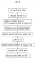
- an inner bag for the transport tank of the present invention includes a synthetic-resin inner bag body having an envelope shape and a second supply-discharge opening fitted in a first supply-discharge opening of the transport tank. Filler is filled in the inner bag body through the second supply-discharge opening.
- the width thereof is IW
- the inner peripheral length of the transport tank in the longitudinal cross-sectional surface in the longitudinal direction is TLt
- the inner peripheral length of the transport tank in the longitudinal cross-sectional surface in the width directio is TLr
- IL and IW satisfy the following conditions: 0.47 ⁇ TLt ⁇ IL ⁇ 0.6 ⁇ TLt, and 0.47 ⁇ TLr ⁇ IW ⁇ 0.6 ⁇ TLr.
- IL and IW satisfy the following conditions: 0.49 ⁇ TLt ⁇ IL ⁇ 0.55 ⁇ TLt, and 0.49 ⁇ TLr ⁇ IW ⁇ 0.58 ⁇ TLr.
- the second supply-discharge opening is provided on a central line extending in the longitudinal direction at a position apart from one end of the inner bag body by a distance L1 or adjacent thereto.
- the distance L1 satisfies the condition: 0.44 ⁇ IW ⁇ L1 ⁇ 0.50 ⁇ IW.
- both ends of the inner bag body are folded inward or rolled toward the second supply-discharge opening in parallel with a central line extending in the width direction so that the inner bag body is folded up.
- the folded inner bag except both side edges opens up in the longitudinal direction.
- the inner bag body has a multilayer structure formed by welding both ends of a multilayer tubular film which is constituted of inner and outer tubular films.
- the inner bag since the inner bag is formed to have the envelope shape, it is unnecessary to shape an inner bag body into tube to have the approximately same shape as the transport tank. It is necessary only to weld both the ends of the tubular film, so that the inner bag body can be produced easily.
- IL and IW satisfy the following conditions: 0.47 ⁇ TLt ⁇ IL ⁇ 0.6 ⁇ TLt, and 0.47 ⁇ TLr ⁇ IW ⁇ 0.6 ⁇ TLr, that enables to produce the envelope type inner bag body of appropriate size. As a result, it is possible to prevent the filling failure and the damage of the inner bag when the envelope type inner bag body is loaded in the approximately tubular transport tank.
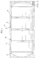
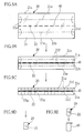
- a twenty-foot ISO container 10 is constituted of a tank body 11 and a rectangular parallelepiped frame 12 for holding the tank body 11.
- a hatch 13 is formed at the top face of the tank body 11. The maintenance and filling of liquid are performed through the hatch 13.
- a lid 14 is locked by a locking member in order to prevent the lid 14 covering the hatch 13 from opening.
- a tank supply-discharge opening 15 is formed in one end of a lower portion of the tank body 11.
- a foot valve 16 is fixed through a flange 15a of the tank supply-discharge opening 15.
- An inner bag for a transport tank (hereinafter referred to as an inner bag) 20 is loaded into the tank body 11.
- the inner bag 20 is brought into the tank body 11 from the hatch 13 by an operating person to set in the tank body 11.
- the inner bag 20 upswells in the tank body 11 by pouring the liquid as cargo therein from the tank supply-discharge opening 15 through the foot valve 16, so that the inner bag 20 operates as a lining to the tank body 11.
- the inner bag 20 is constituted of an inner bag body 21 having an envelope shape and an inner bag supply-discharge opening 22 to be fitted in the tank supply-discharge opening 15. Since the inner bag 20 is formed to the envelope shape, the inner bag body 21 can be easily formed as shown in FIGS.3A - 3D.
- a tubular film 23 is cut into a predetermined length after being drawn from a film roll 24 which is the roll of the tubular film 23, and then both end portions 23a and 23b of the tubular film 23 are closed by thermally welding or the like (see FIGS. 7A and 7C).
- a longitudinal cross-sectional surface including a central line CL1 extending in the longitudinal direction of the tank body 11 is referred to as a longitudinal cross-sectional surface in the longitudinal direction
- a longitudinal cross-sectional surface including a central line CL2 extending in the width direction of the tank body 11 is referred to as a longitudinal cross-sectional surface in the width direction
- a line CL3 shown in FIG.2B is a central line extending in a height direction of the tank body 11.
- the tank body 11 is formed to a tubular shape whose both ends are closed to be placed transversally, while the inner bag 20 is formed to the envelope shape. Therefore, if the inner bag 20 is smaller than the appropriate size corresponding to the size of the tank body 11, a predetermined filling capacity is not ensured. To make matters worse, the smaller inner bag creates a gap between the inner peripheral surface of the tank body 11 and the inner bag 20 where the inner bag 20 together with the liquid can move to damage the welded portion of the inner bag supply-discharge opening 22 and the welded lines of the both ends of the inner bag 20. Whereas, if the inner bag 20 is larger than the appropriate size corresponding to the size of the tank body 11, the raw material of the inner bag 20 is wasted.
- the size of the envelope type inner bag 20 is limited within a specific range based on the size of the tank body 11 for the purpose of preventing the filling failure and the damage of the inner bag 20.
- the length of the inner bag 20 is IL
- the width thereof is IW
- the inner peripheral length (first inner peripheral length) of the tank body 11 in the longitudinal cross-sectional surface in the longitudinal direction is TLt
- the inner peripheral length (second inner peripheral length) of the tank body 11 in the longitudinal cross-sectional surface in the width direction is TLr
- the following conditions are satisfied: 0.47 ⁇ TLt ⁇ IL ⁇ 0.6 ⁇ TLt; and 0.47 ⁇ TLr ⁇ IW ⁇ 0.6 ⁇ TLr.
- IL and IW preferably satisfy the following conditions: 0.49 ⁇ TLt ⁇ IL ⁇ 0.55 ⁇ TLt; and 0.49 ⁇ TLr ⁇ IW ⁇ 0.58 ⁇ TLr.
- the size of the inner bag 20 is limited based on the inner peripheral length of the tank body 11, so that the tank body 11 may have different shapes than tube such as an elliptical shape or others.
- the distance L1 is limited within a range 0.44 ⁇ IW ⁇ L1 ⁇ 0.50 ⁇ IW based on the width IW of the inner bag 20, so that it is possible to position the central positions in the longitudinal direction of the tank body 11 and the inner bag 20 with each other if the inner bag 20 is attached to the tank body 11 with reference to the tank supply-discharge opening 15, which is formed in the end of the lower portion of the tank body 11.
- the extra portions in both ends of the inner bag 20 can be distributed approximately evenly in the tank body 11. Accordingly, the extra portion of the inner bag 20 dose not build up on one side to be sandwiched between the tank body 11 and the inner bag body 21, so that the filling failure and the damage of the inner bag 20 are eliminated.
- the tubular film 23 is drawn from the film roll 24 to be put on a work table 25, and then cut into the length IL by a cutter 26 or the like.
- the tubular film 23 is made from LLDPE (linear low density polyethylene), and wound into a roll shape to be stored. Since the inner bag 20 is doubled in the present embodiment, it is necessary to form the two tubular films 23 by cutting the tubular film 23 twice into the length IL.
- the thickness of a single layer of the tubular film 23 is 120 ⁇ m. Since the tubular film 23 of the present embodiment has two layers, the entire thickness of the tubular film 23 is 240 ⁇ m.
- the thickness of the film is preferably 80 - 500 ⁇ m, especially 100 - 300 ⁇ m.
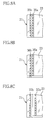
- FIG.3C in doubling the tubular film 23, one tubular film is inserted into another tubular film. Subsequently, as shown in FIG.3D, a hole 27 corresponding to the inner bag supply-discharge opening 22 is opened on only the upper two layers of films by a punch or a cutter.
- the inner bag supply-discharge opening 22 is constituted of a supply-discharge mouth 22a having a truncated conical and cylindrical shape, a welding flange 22b and an attachment flange 22c which are attached to both the ends of the supply-discharge mouth 22a, and integrally formed by using LLDPE for example.
- the welding flange 22b and the inner bag body 21 are thermally welded by a thermal welding apparatus (not shown) to form weld lines 28 and 29. As shown in FIG.
- a flange 30a of an inner bag suction preventing member 30 and the foot valve 16 are attached to the flange 15a of the tank supply-discharge opening 15, so that the inner bag supply-discharge opening 22 is attached firmly to the tank supply-discharge opening 15.
- the supply-discharge mouth 22a is formed along the inner peripheral surface of the tank supply-discharge opening 15.
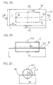
- the thermally welding apparatus 33 is constituted of a receiving stage 33a and a welding head 33b. The heat is applied to the end portion 23a, which is held by the welding head 33b and the receiving stage 33a after the welding head 33b has been moved down.
- thermal welding lines 35a and 35b of 5 mm in width are formed linearly at an interval of 5-10mm.
- one or three or more thermal welding lines may be formed.
- a corrugated thermal welding line may be applied to the present embodiment instead of the linear one. If the plural thermal welding lines are formed, all lines may be formed together, or each line may be formed one by one.
- a thermal welding line 36a is formed by welding the one end portion of the inner tubular film 23 into two layer, and then a thermal welding line 36b is formed by welding the one end portion of both the inner and outer tubular films 23 into four layer. The thermal welding line 36b is positioned outside the thermal welding line 36a.
- thermal welding lines 37a and 37b are formed by welding each end portion of the tubular film 23 into two layer separately wherein the inner tubular film is slightly shorter in length than the outer one.
- the thermal welding line may be welded at a time, if the length of the welding head 33b is limited, the thermal welding line may be welded sequentially every length of the welding head 33b.
- ultrasonic welding or other welding method may be applied to the present embodiment instead of the thermal welding by using the heat-sealing type thermal welding apparatus 33.
- a pressing roller 38 is rotated on the work table 25 from the welded end portion 23a toward the other end portion 23b to vent air 39 in the doubled tubular film 23.
- the air may be vented by folding the inner bag body 21 from one end side to the other end side. Since the inner bag supply-discharge opening 22 is attached close to the other end portion 23b so as to protrude from the inner bag body 21, the air between the inner bag supply-discharge opening 22 and the other end portion 23b is vented by using a small roller for avoiding the supply-discharge opening 22.
- the other end portion 23b of tubular film 23, in which the air has been vented, is welded by the thermal welding apparatus 33 as well as the case of the end portion 23a.
- the inner bag 20 shown in FIG.9A is completed.
- a positioning mark 45 is recorded thereon along a central line extending in the longitudinal direction of the inner bag 20 by using an oil-based ink or the like.
- the inner bag body 21 is folded, and then contained in a packaging bag 40 as shown in FIG.9E.
- the positioning mark 45 is formed linearly in the present embodiment, the shape or size of the positioning mark is not limited especially.
- the inner bag body 21 with the supply-discharge opening 22 directed downward is folded inward along inward folding lines 21e in parallel with the positioning mark 45 so as to make both the side edge portions 21a and 21b approach the central line.
- the inward-folded portions are folded inward again along inward folding lines 21f in parallel with the central line extending in the longitudinal direction so as to make the inward folding line 21e approach the central line.
- the inner bag body 21 is double folded. Subsequently, as shown in FIG.
- the inner bag body 21 is folded plural times along the inward folding lines 21g toward the inner bag supply-discharge opening 22 from both the end portions 21c and 21d of the inner bag body 21, so that the inner bag body 21 is folded into a small size as shown in FIG.9D.
- the inner bag body 21 may be rewound from the one end to be a roll shape instead of being folded inward along the inward folding lines 21g.
- the inner bag 20 is put in the packaging bag 40 as shown in FIG.9E. Since the inner bag body 21 is double folded along the inward folding lines 21e and 21f, it can be contained compactly. Note that the inner bag body 21 may be folded once or three times and above along the central line extending in the longitudinal direction.
- the inner bag body 21 is folded such that the inner bag supply-discharge opening 22 is directed outside the inner bag body 21, the inner bag supply-discharge opening 22 can be inserted to the tank supply-discharge opening 15 easily.
- the inner bag body 21 is folded inward along the inward folding lines 21g, so that the inner bag body 21 can be expanded easily in the longitudinal direction of the tank body 11 in a state that the inner bag supply-discharge opening 22 is set in the tank supply-discharge opening 15.
- the inner bag body 21 is folded inward along each of the inward folding lines 21e and 21f in a state that the inner bag supply-discharge opening 22 is directed downward, the inner bag body 21 is expanded by itself by filling the liquid from the inner bag supply-discharge opening 22.
- the inner bag 20 in the packaging bag 40 is brought into the tank body 11 by the operating person to be taken out of the packaging bag 40.
- the positioning mark 45 is recorded linearly on the inner bag 20 so as to correspond to the central line CL1 extending in the longitudinal direction of the tank body 11.
- the inner bag supply-discharge opening 22 is inserted in the tank supply-discharge opening 15 so as to conform the positioning mark 45 to the central line CL1.
- the attachment flange 22c is attached firmly to the flange 15a.
- the inner bag body 21 folded along the inward folding lines 21g is unfolded in the longitudinal direction of the tank body 11, and then the folded portions along the inward folding line 21f are unfolded. Both the side edge portions which is folded along the inward folding lines 21e are not unfolded. Since the approximately overall width of the inside of the tank body 11 is covered by the inner bag body 21 of which the both side edge portions are folded along the inward folding lines 21e, even if the both side edge portions are unfolded, they are folded again by their weight. After unfolding the inner bag body 21 except for both the side edge portions, the inner bag suction preventing member 30 and the foot valve 16 are attached to the tank supply-discharge opening 15 from the outside of the tank body 11 as shown in FIG.6.
- the liquid as the cargo is filled from the tank supply-discharge opening 15.
- the filling speed is 50 liters per minute, for example.
- the inner bag body 21 is extended in the longitudinal direction in the tank body 11, so that the inner bag body 21 upswells by filling the liquid in the inner bag body 21 smoothly.
- the both side edge portions of the inner bag body 21, which are folded inward, are gradually unfolded with the filling of the liquid, so that the end portions of the inner bag body 21 are not accidentally caught between the inner bag body 21 and the tank body 11 by the weight of the portion in which the liquid is filled. Therefore, the inner bag body 21 upswells smoothly by the filling of the liquid. In a full filled state, about 20 tons of liquid is contained in the inner bag body 21.
- the inner bag body 21 is loaded in the tank body 11 to extend in the longitudinal direction, and its side edge portions are folded inward toward the central line extending in the width direction of the inner bag body 21. That prevents the air from entering the inner bag body 21 and the inner bag body 21 can be used for the anaerobic liquid.
- the inner bag body 21 and the inner bag supply-discharge opening 22 are made from LLDPE having high chemical resistance, the tank body 11 has more choices in material. Furthermore, it is unnecessary to line the inner peripheral surface of the tank body 11 with fluorocarbon resin such as polytetrafluoroethylene.
- the inner bag body 21 When the inner bag body 21 dwindles to close with the inner bag supply-discharge opening 22 after the remaining amount of the liquid is reduced, the inner bag body 21 may be accidentally sucked into the inner bag supply-discharge opening 22 to cover the opening 22.
- the inner bag suction preventing member 30 In order to prevent the inner bag body 21 from covering the inner bag supply-discharge opening 22 in discharging the liquid from the tank supply-discharge opening 15, when the liquid is discharged from the tank supply-discharge opening 15, a passage between the inner bag body 21 and the inner bag supply-discharge opening 22 is ensured by the inner bag suction preventing member 30.
- the inner bag suction preventing member 30 is integrally constituted of a semi-spherical end 30b arranged to protrude toward the inside of the tank body 11, a tubular portion 30d whose peripheral surface has plural continuous holes 30c, and an attachment flange 30a provided on the base of the tubular portion 30d.
- the semi-spherical end 30b protrudes toward the inside of the inner bag body 21, so that the residual liquid in the inner bag body 21 can be surely discharged through the continuous holes 30c without the inner bag body 21 stick to the inner bag supply-discharge opening 22.
- an air vent cap and an air vent valve may be welded to the inner bag body 21 at a position corresponding to the hatch 13. In this case, if the air enters the inner bag body 21 by the operation of loading the inner bag body 21 or filling the liquid, the air can be vented easily.
- the inner bag body 21 is made from LLDPE, it may be made from LDPE (low-density polyethylene), OP (biaxially oriented polypropylene) and other synthetic resin.
- LDPE low-density polyethylene
- OP biaxially oriented polypropylene
- the inner bag body 21 is doubled in the present embodiment, it may have a multilayer or single-layer structure.
- the inner bag 20 may be used not only for the tank container, but also for a tanker lorry and so forth.
Landscapes
- Engineering & Computer Science (AREA)
- Mechanical Engineering (AREA)
- Packages (AREA)
- Bag Frames (AREA)
- Basic Packing Technique (AREA)
Applications Claiming Priority (4)
| Application Number | Priority Date | Filing Date | Title |
|---|---|---|---|
| JP2004008246 | 2004-01-15 | ||
| JP2004008246 | 2004-01-15 | ||
| JP2004062780A JP4390054B2 (ja) | 2004-01-15 | 2004-03-05 | 輸送タンク用内袋 |
| JP2004062780 | 2004-03-05 |
Publications (2)
| Publication Number | Publication Date |
|---|---|
| EP1555221A2 true EP1555221A2 (fr) | 2005-07-20 |
| EP1555221A3 EP1555221A3 (fr) | 2008-12-10 |
Family
ID=34622260
Family Applications (1)
| Application Number | Title | Priority Date | Filing Date |
|---|---|---|---|
| EP05000823A Withdrawn EP1555221A3 (fr) | 2004-01-15 | 2005-01-17 | Sac intérieure pour une citerne de transport |
Country Status (3)
| Country | Link |
|---|---|
| US (1) | US7490990B2 (fr) |
| EP (1) | EP1555221A3 (fr) |
| JP (1) | JP4390054B2 (fr) |
Families Citing this family (3)
| Publication number | Priority date | Publication date | Assignee | Title |
|---|---|---|---|---|
| DE102007047680B4 (de) * | 2007-10-05 | 2009-11-26 | Multitest Elektronische Systeme Gmbh | Handhabungsvorrichtung für elektronische Bauelemente, insbesondere IC's, mit temperierbaren Umlaufeinheiten |
| US8651314B2 (en) * | 2010-07-21 | 2014-02-18 | I Hsing Lin | Foam tank structure improvement |
| US10807794B2 (en) * | 2018-02-05 | 2020-10-20 | Composite Containers, Llc | Liner for tank container |
Family Cites Families (17)
| Publication number | Priority date | Publication date | Assignee | Title |
|---|---|---|---|---|
| US3167209A (en) * | 1957-11-20 | 1965-01-26 | Wayne W Jones | Flexible tank liner |
| US3219240A (en) * | 1962-12-14 | 1965-11-23 | Weyerhaeuser Co | Shipping and dispensing container for liquids |
| FR2207068B1 (fr) | 1972-11-20 | 1978-02-03 | Vidilles Jacques | |
| JPS6115029Y2 (fr) | 1980-09-02 | 1986-05-10 | ||
| SE8207336L (sv) | 1982-12-22 | 1984-06-23 | Clean Pak Ab | Forfarande vid transport/lagringsbehallare |
| US4671733A (en) * | 1983-06-09 | 1987-06-09 | Reuben Krein | Free standing, waterproof lining for truck industry |
| JPS6148190U (ja) | 1984-09-04 | 1986-03-31 | 東急車輌製造株式会社 | コンテナ |
| JPS61104983A (ja) | 1984-10-26 | 1986-05-23 | 与那原 好宏 | 液体輸送容器 |
| DE3725828A1 (de) | 1987-08-04 | 1989-02-16 | Nittel Gmbh & Co Kg | Verfahren zur herstellung einer flexiblen innenhuelle fuer zylindrische tanks |
| DE3818721A1 (de) | 1988-06-01 | 1989-12-21 | Nalco Chemical Co | Behaelter fuer ein fluid, insbesondere transport- und lagerbehaelter, verfahren zum befuellen eines solchen behaelters und verfahren zur entnahme des fluids sowie foliengebilde fuer das behaeltersystem |
| GB2237559A (en) | 1989-11-02 | 1991-05-08 | Joseph Patrick Dempsey | Lined containers |
| US5098364A (en) * | 1990-03-26 | 1992-03-24 | Pactec, Inc. | Waste container liner and method for manufacturing same |
| US5741208A (en) * | 1996-10-15 | 1998-04-21 | Industrial Transportation, Inc. | Environmental container liner and method of manufacture |
| US6203089B1 (en) * | 1999-12-17 | 2001-03-20 | Daimlerchrysler Corporation | Device for transforming the interior of a van or a sport utility vehicle into a work vehicle |
| JP2001354292A (ja) | 2000-06-13 | 2001-12-25 | Kyoritsu Butsuryu System:Kk | 液体コンテナ用の内袋 |
| US6626312B2 (en) * | 2000-06-28 | 2003-09-30 | Javier Urzua Maturana | Storage bag |
| JP4297809B2 (ja) * | 2004-01-30 | 2009-07-15 | 富士フイルム株式会社 | 輸送タンク用内袋の装填方法 |
-
2004
- 2004-03-05 JP JP2004062780A patent/JP4390054B2/ja not_active Expired - Lifetime
-
2005
- 2005-01-13 US US11/033,833 patent/US7490990B2/en active Active
- 2005-01-17 EP EP05000823A patent/EP1555221A3/fr not_active Withdrawn
Also Published As
| Publication number | Publication date |
|---|---|
| JP2005225556A (ja) | 2005-08-25 |
| US20050184068A1 (en) | 2005-08-25 |
| EP1555221A3 (fr) | 2008-12-10 |
| US7490990B2 (en) | 2009-02-17 |
| JP4390054B2 (ja) | 2009-12-24 |
Similar Documents
| Publication | Publication Date | Title |
|---|---|---|
| US5851072A (en) | Spout construction for bulk box liquid liner | |
| JP5864175B2 (ja) | 液体容器への液体充填方法 | |
| PL184854B1 (pl) | Pojemnik opakowaniowy z substancją i sposób wytwarzania pojemnika opakowaniowego z substancją | |
| US7086429B2 (en) | Inner bag for transport tank and loading method thereof | |
| US20200207049A1 (en) | Method and apparatus for manufacturing spouted pouch containers | |
| US20100189528A1 (en) | Dunnage bag with double seal reusable inflation valve | |
| EP1568622A1 (fr) | Réservoir de transport et procédé de transport d'un chargement | |
| KR20100119504A (ko) | 유체용 용기 | |
| JP6673946B2 (ja) | フォイル裏打ちfibc(バルクバッグ)用のハーメチックシール | |
| US7490990B2 (en) | Inner bag for transport tank | |
| US7275869B2 (en) | Inner bag for transport tank and producing method thereof | |
| EP1940701A1 (fr) | Recipient a fluide | |
| US9517874B2 (en) | Valve structure | |
| CN111532570B (zh) | 用于箔衬里散装袋的气密密封件 | |
| JP2005239267A (ja) | 輸送タンク内袋の製造方法 | |
| JP2005239263A (ja) | 輸送タンク用内袋及びその製造方法 | |
| JP7800205B2 (ja) | パウチ製造方法およびパウチ中間体 | |
| JP7496064B2 (ja) | 収納容器、組合容器、内容物入り組合容器、設置方法、内容物入り組合容器の製造方法、内容物入り組合容器の使用方法、収納容器の製造方法および環状部材付き収納容器 | |
| US10807794B2 (en) | Liner for tank container | |
| JP2005239264A (ja) | 輸送タンク用内袋及びその製造方法 | |
| WO2007088388A1 (fr) | Systeme et procede destines au transport de liquides ou de solides s'ecoulant librement et contenant | |
| AU2008212006A1 (en) | A bag | |
| JPH0976372A (ja) | 封筒成形装置 |
Legal Events
| Date | Code | Title | Description |
|---|---|---|---|
| PUAI | Public reference made under article 153(3) epc to a published international application that has entered the european phase |
Free format text: ORIGINAL CODE: 0009012 |
|
| AK | Designated contracting states |
Kind code of ref document: A2 Designated state(s): AT BE BG CH CY CZ DE DK EE ES FI FR GB GR HU IE IS IT LI LT LU MC NL PL PT RO SE SI SK TR |
|
| AX | Request for extension of the european patent |
Extension state: AL BA HR LV MK YU |
|
| RAP1 | Party data changed (applicant data changed or rights of an application transferred) |
Owner name: FUJIFILM CORPORATION |
|
| PUAL | Search report despatched |
Free format text: ORIGINAL CODE: 0009013 |
|
| AK | Designated contracting states |
Kind code of ref document: A3 Designated state(s): AT BE BG CH CY CZ DE DK EE ES FI FR GB GR HU IE IS IT LI LT LU MC NL PL PT RO SE SI SK TR |
|
| AX | Request for extension of the european patent |
Extension state: AL BA HR LV MK YU |
|
| STAA | Information on the status of an ep patent application or granted ep patent |
Free format text: STATUS: THE APPLICATION HAS BEEN WITHDRAWN |
|
| 18W | Application withdrawn |
Effective date: 20090407 |