EP1555106B1 - Transparente flächige Kunststoff-Fensterscheibe eines Kraftfahrzeugs mit kaschierter Anguss-Stelle , Verfahren zur Herstellung derselben und Verwendung derselben - Google Patents
Transparente flächige Kunststoff-Fensterscheibe eines Kraftfahrzeugs mit kaschierter Anguss-Stelle , Verfahren zur Herstellung derselben und Verwendung derselben Download PDFInfo
- Publication number
- EP1555106B1 EP1555106B1 EP05000727A EP05000727A EP1555106B1 EP 1555106 B1 EP1555106 B1 EP 1555106B1 EP 05000727 A EP05000727 A EP 05000727A EP 05000727 A EP05000727 A EP 05000727A EP 1555106 B1 EP1555106 B1 EP 1555106B1
- Authority
- EP
- European Patent Office
- Prior art keywords
- window pane
- plastic window
- plastic
- sprue
- motor vehicle
- Prior art date
- Legal status (The legal status is an assumption and is not a legal conclusion. Google has not performed a legal analysis and makes no representation as to the accuracy of the status listed.)
- Revoked
Links
- 229920003023 plastic Polymers 0.000 title claims description 129
- 239000004033 plastic Substances 0.000 title claims description 116
- 238000000034 method Methods 0.000 title claims description 23
- 238000002347 injection Methods 0.000 title claims description 18
- 239000007924 injection Substances 0.000 title claims description 18
- 238000004519 manufacturing process Methods 0.000 title claims description 16
- 230000003287 optical effect Effects 0.000 claims description 42
- 239000000463 material Substances 0.000 claims description 40
- 238000001746 injection moulding Methods 0.000 claims description 12
- 238000000926 separation method Methods 0.000 claims description 10
- 239000003973 paint Substances 0.000 claims description 4
- 230000000903 blocking effect Effects 0.000 claims description 2
- 239000000206 moulding compound Substances 0.000 claims 1
- 238000000465 moulding Methods 0.000 description 10
- 150000001875 compounds Chemical class 0.000 description 5
- 238000007598 dipping method Methods 0.000 description 4
- 239000007788 liquid Substances 0.000 description 4
- 238000010137 moulding (plastic) Methods 0.000 description 4
- 230000008447 perception Effects 0.000 description 4
- 230000007547 defect Effects 0.000 description 3
- 230000000873 masking effect Effects 0.000 description 3
- 239000002991 molded plastic Substances 0.000 description 3
- 241001074085 Scophthalmus aquosus Species 0.000 description 2
- 238000005266 casting Methods 0.000 description 2
- 238000010276 construction Methods 0.000 description 2
- 238000005429 filling process Methods 0.000 description 2
- 238000010030 laminating Methods 0.000 description 2
- 230000007246 mechanism Effects 0.000 description 2
- 230000002093 peripheral effect Effects 0.000 description 2
- 239000002985 plastic film Substances 0.000 description 2
- 239000000243 solution Substances 0.000 description 2
- 239000011248 coating agent Substances 0.000 description 1
- 238000000576 coating method Methods 0.000 description 1
- 230000000295 complement effect Effects 0.000 description 1
- 238000001816 cooling Methods 0.000 description 1
- 238000011161 development Methods 0.000 description 1
- 230000018109 developmental process Effects 0.000 description 1
- 230000000694 effects Effects 0.000 description 1
- 230000004927 fusion Effects 0.000 description 1
- 239000011521 glass Substances 0.000 description 1
- 238000003475 lamination Methods 0.000 description 1
- 230000001766 physiological effect Effects 0.000 description 1
- 238000007711 solidification Methods 0.000 description 1
- 230000008023 solidification Effects 0.000 description 1
- 238000005507 spraying Methods 0.000 description 1
Images
Classifications
-
- B—PERFORMING OPERATIONS; TRANSPORTING
- B29—WORKING OF PLASTICS; WORKING OF SUBSTANCES IN A PLASTIC STATE IN GENERAL
- B29C—SHAPING OR JOINING OF PLASTICS; SHAPING OF MATERIAL IN A PLASTIC STATE, NOT OTHERWISE PROVIDED FOR; AFTER-TREATMENT OF THE SHAPED PRODUCTS, e.g. REPAIRING
- B29C45/00—Injection moulding, i.e. forcing the required volume of moulding material through a nozzle into a closed mould; Apparatus therefor
- B29C45/0053—Injection moulding, i.e. forcing the required volume of moulding material through a nozzle into a closed mould; Apparatus therefor combined with a final operation, e.g. shaping
-
- B—PERFORMING OPERATIONS; TRANSPORTING
- B29—WORKING OF PLASTICS; WORKING OF SUBSTANCES IN A PLASTIC STATE IN GENERAL
- B29C—SHAPING OR JOINING OF PLASTICS; SHAPING OF MATERIAL IN A PLASTIC STATE, NOT OTHERWISE PROVIDED FOR; AFTER-TREATMENT OF THE SHAPED PRODUCTS, e.g. REPAIRING
- B29C45/00—Injection moulding, i.e. forcing the required volume of moulding material through a nozzle into a closed mould; Apparatus therefor
- B29C45/16—Making multilayered or multicoloured articles
-
- B—PERFORMING OPERATIONS; TRANSPORTING
- B60—VEHICLES IN GENERAL
- B60J—WINDOWS, WINDSCREENS, NON-FIXED ROOFS, DOORS, OR SIMILAR DEVICES FOR VEHICLES; REMOVABLE EXTERNAL PROTECTIVE COVERINGS SPECIALLY ADAPTED FOR VEHICLES
- B60J1/00—Windows; Windscreens; Accessories therefor
-
- B—PERFORMING OPERATIONS; TRANSPORTING
- B29—WORKING OF PLASTICS; WORKING OF SUBSTANCES IN A PLASTIC STATE IN GENERAL
- B29C—SHAPING OR JOINING OF PLASTICS; SHAPING OF MATERIAL IN A PLASTIC STATE, NOT OTHERWISE PROVIDED FOR; AFTER-TREATMENT OF THE SHAPED PRODUCTS, e.g. REPAIRING
- B29C45/00—Injection moulding, i.e. forcing the required volume of moulding material through a nozzle into a closed mould; Apparatus therefor
- B29C45/0025—Preventing defects on the moulded article, e.g. weld lines, shrinkage marks
- B29C2045/0027—Gate or gate mark locations
-
- B—PERFORMING OPERATIONS; TRANSPORTING
- B29—WORKING OF PLASTICS; WORKING OF SUBSTANCES IN A PLASTIC STATE IN GENERAL
- B29C—SHAPING OR JOINING OF PLASTICS; SHAPING OF MATERIAL IN A PLASTIC STATE, NOT OTHERWISE PROVIDED FOR; AFTER-TREATMENT OF THE SHAPED PRODUCTS, e.g. REPAIRING
- B29C45/00—Injection moulding, i.e. forcing the required volume of moulding material through a nozzle into a closed mould; Apparatus therefor
- B29C45/0053—Injection moulding, i.e. forcing the required volume of moulding material through a nozzle into a closed mould; Apparatus therefor combined with a final operation, e.g. shaping
- B29C2045/0079—Injection moulding, i.e. forcing the required volume of moulding material through a nozzle into a closed mould; Apparatus therefor combined with a final operation, e.g. shaping applying a coating or covering
-
- B—PERFORMING OPERATIONS; TRANSPORTING
- B29—WORKING OF PLASTICS; WORKING OF SUBSTANCES IN A PLASTIC STATE IN GENERAL
- B29C—SHAPING OR JOINING OF PLASTICS; SHAPING OF MATERIAL IN A PLASTIC STATE, NOT OTHERWISE PROVIDED FOR; AFTER-TREATMENT OF THE SHAPED PRODUCTS, e.g. REPAIRING
- B29C45/00—Injection moulding, i.e. forcing the required volume of moulding material through a nozzle into a closed mould; Apparatus therefor
- B29C45/16—Making multilayered or multicoloured articles
- B29C2045/1682—Making multilayered or multicoloured articles preventing defects
-
- B—PERFORMING OPERATIONS; TRANSPORTING
- B29—WORKING OF PLASTICS; WORKING OF SUBSTANCES IN A PLASTIC STATE IN GENERAL
- B29C—SHAPING OR JOINING OF PLASTICS; SHAPING OF MATERIAL IN A PLASTIC STATE, NOT OTHERWISE PROVIDED FOR; AFTER-TREATMENT OF THE SHAPED PRODUCTS, e.g. REPAIRING
- B29C45/00—Injection moulding, i.e. forcing the required volume of moulding material through a nozzle into a closed mould; Apparatus therefor
- B29C45/0025—Preventing defects on the moulded article, e.g. weld lines, shrinkage marks
-
- B—PERFORMING OPERATIONS; TRANSPORTING
- B29—WORKING OF PLASTICS; WORKING OF SUBSTANCES IN A PLASTIC STATE IN GENERAL
- B29C—SHAPING OR JOINING OF PLASTICS; SHAPING OF MATERIAL IN A PLASTIC STATE, NOT OTHERWISE PROVIDED FOR; AFTER-TREATMENT OF THE SHAPED PRODUCTS, e.g. REPAIRING
- B29C45/00—Injection moulding, i.e. forcing the required volume of moulding material through a nozzle into a closed mould; Apparatus therefor
- B29C45/17—Component parts, details or accessories; Auxiliary operations
- B29C45/26—Moulds
- B29C45/27—Sprue channels ; Runner channels or runner nozzles
- B29C45/28—Closure devices therefor
- B29C45/2803—Closure devices therefor comprising a member with an opening or the injection nozzle movable into or out of alignment with the sprue channel or mould gate
-
- B—PERFORMING OPERATIONS; TRANSPORTING
- B29—WORKING OF PLASTICS; WORKING OF SUBSTANCES IN A PLASTIC STATE IN GENERAL
- B29K—INDEXING SCHEME ASSOCIATED WITH SUBCLASSES B29B, B29C OR B29D, RELATING TO MOULDING MATERIALS OR TO MATERIALS FOR MOULDS, REINFORCEMENTS, FILLERS OR PREFORMED PARTS, e.g. INSERTS
- B29K2995/00—Properties of moulding materials, reinforcements, fillers, preformed parts or moulds
- B29K2995/0018—Properties of moulding materials, reinforcements, fillers, preformed parts or moulds having particular optical properties, e.g. fluorescent or phosphorescent
- B29K2995/0025—Opaque
-
- B—PERFORMING OPERATIONS; TRANSPORTING
- B29—WORKING OF PLASTICS; WORKING OF SUBSTANCES IN A PLASTIC STATE IN GENERAL
- B29K—INDEXING SCHEME ASSOCIATED WITH SUBCLASSES B29B, B29C OR B29D, RELATING TO MOULDING MATERIALS OR TO MATERIALS FOR MOULDS, REINFORCEMENTS, FILLERS OR PREFORMED PARTS, e.g. INSERTS
- B29K2995/00—Properties of moulding materials, reinforcements, fillers, preformed parts or moulds
- B29K2995/0018—Properties of moulding materials, reinforcements, fillers, preformed parts or moulds having particular optical properties, e.g. fluorescent or phosphorescent
- B29K2995/0026—Transparent
-
- B—PERFORMING OPERATIONS; TRANSPORTING
- B29—WORKING OF PLASTICS; WORKING OF SUBSTANCES IN A PLASTIC STATE IN GENERAL
- B29L—INDEXING SCHEME ASSOCIATED WITH SUBCLASS B29C, RELATING TO PARTICULAR ARTICLES
- B29L2012/00—Frames
-
- B—PERFORMING OPERATIONS; TRANSPORTING
- B29—WORKING OF PLASTICS; WORKING OF SUBSTANCES IN A PLASTIC STATE IN GENERAL
- B29L—INDEXING SCHEME ASSOCIATED WITH SUBCLASS B29C, RELATING TO PARTICULAR ARTICLES
- B29L2031/00—Other particular articles
- B29L2031/30—Vehicles, e.g. ships or aircraft, or body parts thereof
-
- B—PERFORMING OPERATIONS; TRANSPORTING
- B29—WORKING OF PLASTICS; WORKING OF SUBSTANCES IN A PLASTIC STATE IN GENERAL
- B29L—INDEXING SCHEME ASSOCIATED WITH SUBCLASS B29C, RELATING TO PARTICULAR ARTICLES
- B29L2031/00—Other particular articles
- B29L2031/778—Windows
-
- B—PERFORMING OPERATIONS; TRANSPORTING
- B29—WORKING OF PLASTICS; WORKING OF SUBSTANCES IN A PLASTIC STATE IN GENERAL
- B29L—INDEXING SCHEME ASSOCIATED WITH SUBCLASS B29C, RELATING TO PARTICULAR ARTICLES
- B29L2031/00—Other particular articles
- B29L2031/778—Windows
- B29L2031/7782—Glazing
-
- Y—GENERAL TAGGING OF NEW TECHNOLOGICAL DEVELOPMENTS; GENERAL TAGGING OF CROSS-SECTIONAL TECHNOLOGIES SPANNING OVER SEVERAL SECTIONS OF THE IPC; TECHNICAL SUBJECTS COVERED BY FORMER USPC CROSS-REFERENCE ART COLLECTIONS [XRACs] AND DIGESTS
- Y10—TECHNICAL SUBJECTS COVERED BY FORMER USPC
- Y10T—TECHNICAL SUBJECTS COVERED BY FORMER US CLASSIFICATION
- Y10T428/00—Stock material or miscellaneous articles
- Y10T428/24—Structurally defined web or sheet [e.g., overall dimension, etc.]
- Y10T428/24479—Structurally defined web or sheet [e.g., overall dimension, etc.] including variation in thickness
- Y10T428/24521—Structurally defined web or sheet [e.g., overall dimension, etc.] including variation in thickness with component conforming to contour of nonplanar surface
-
- Y—GENERAL TAGGING OF NEW TECHNOLOGICAL DEVELOPMENTS; GENERAL TAGGING OF CROSS-SECTIONAL TECHNOLOGIES SPANNING OVER SEVERAL SECTIONS OF THE IPC; TECHNICAL SUBJECTS COVERED BY FORMER USPC CROSS-REFERENCE ART COLLECTIONS [XRACs] AND DIGESTS
- Y10—TECHNICAL SUBJECTS COVERED BY FORMER USPC
- Y10T—TECHNICAL SUBJECTS COVERED BY FORMER US CLASSIFICATION
- Y10T428/00—Stock material or miscellaneous articles
- Y10T428/24—Structurally defined web or sheet [e.g., overall dimension, etc.]
- Y10T428/24479—Structurally defined web or sheet [e.g., overall dimension, etc.] including variation in thickness
- Y10T428/24521—Structurally defined web or sheet [e.g., overall dimension, etc.] including variation in thickness with component conforming to contour of nonplanar surface
- Y10T428/24545—Containing metal or metal compound
-
- Y—GENERAL TAGGING OF NEW TECHNOLOGICAL DEVELOPMENTS; GENERAL TAGGING OF CROSS-SECTIONAL TECHNOLOGIES SPANNING OVER SEVERAL SECTIONS OF THE IPC; TECHNICAL SUBJECTS COVERED BY FORMER USPC CROSS-REFERENCE ART COLLECTIONS [XRACs] AND DIGESTS
- Y10—TECHNICAL SUBJECTS COVERED BY FORMER USPC
- Y10T—TECHNICAL SUBJECTS COVERED BY FORMER US CLASSIFICATION
- Y10T428/00—Stock material or miscellaneous articles
- Y10T428/24—Structurally defined web or sheet [e.g., overall dimension, etc.]
- Y10T428/24479—Structurally defined web or sheet [e.g., overall dimension, etc.] including variation in thickness
- Y10T428/24612—Composite web or sheet
-
- Y—GENERAL TAGGING OF NEW TECHNOLOGICAL DEVELOPMENTS; GENERAL TAGGING OF CROSS-SECTIONAL TECHNOLOGIES SPANNING OVER SEVERAL SECTIONS OF THE IPC; TECHNICAL SUBJECTS COVERED BY FORMER USPC CROSS-REFERENCE ART COLLECTIONS [XRACs] AND DIGESTS
- Y10—TECHNICAL SUBJECTS COVERED BY FORMER USPC
- Y10T—TECHNICAL SUBJECTS COVERED BY FORMER US CLASSIFICATION
- Y10T428/00—Stock material or miscellaneous articles
- Y10T428/24—Structurally defined web or sheet [e.g., overall dimension, etc.]
- Y10T428/24777—Edge feature
-
- Y—GENERAL TAGGING OF NEW TECHNOLOGICAL DEVELOPMENTS; GENERAL TAGGING OF CROSS-SECTIONAL TECHNOLOGIES SPANNING OVER SEVERAL SECTIONS OF THE IPC; TECHNICAL SUBJECTS COVERED BY FORMER USPC CROSS-REFERENCE ART COLLECTIONS [XRACs] AND DIGESTS
- Y10—TECHNICAL SUBJECTS COVERED BY FORMER USPC
- Y10T—TECHNICAL SUBJECTS COVERED BY FORMER US CLASSIFICATION
- Y10T428/00—Stock material or miscellaneous articles
- Y10T428/24—Structurally defined web or sheet [e.g., overall dimension, etc.]
- Y10T428/24802—Discontinuous or differential coating, impregnation or bond [e.g., artwork, printing, retouched photograph, etc.]
- Y10T428/24893—Discontinuous or differential coating, impregnation or bond [e.g., artwork, printing, retouched photograph, etc.] including particulate material
- Y10T428/24901—Discontinuous or differential coating, impregnation or bond [e.g., artwork, printing, retouched photograph, etc.] including particulate material including coloring matter
Definitions
- the invention relates to a transparent flat plastic Fernstena a motor vehicle, a method for producing the same and the use thereof.
- the so-called Filmanguss method is used.
- the molding of the molding takes place laterally outside of the mold cavity, in which the molded part is produced (so-called "indirect gating").
- a so-called film plate is provided between the injection point and an edge region of the mold cavity designed as a sprue extension. in which sprue channels are incorporated, which distribute starting from the injection point on the film plate and connect the film plate over the entire width of the mold cavity to this.
- the molded part is removed from the open tool, wherein the supplied via the film plate plastic compound as Sprusskaltkanäle integrally formed in lateral extension of the molding of this (so-called runner extension).
- Direct injection method in which the plastic material is introduced directly from the hot runner into the mold cavity, for example via a needle valve nozzle or a gate valve, are already used for the production of non-optical moldings. Unlike the Filmanguss technique, the plastic supply is not carried out laterally in the direction of the surface plane of the molding, but on a surface of the molding.
- the main advantage of direct injection is that it eliminates the sprue separation required by the standard film casting process and the associated additional material costs.
- the font WO 99/44802 describes a transparent plastic disc, which is produced by lateral injection over a Filmanitati. The sprue remains on the plastic disc and is encapsulated by a second, non-transparent component.
- the present invention has for its object to provide a transparent sheet-like plastic window of a motor vehicle with ongoing optical properties and low material costs. Furthermore, it is an object of the invention to provide a method for producing such a plastic window pane.
- Covering the gate by the cover material ensures that the gate is "back-shaded", ie, there is substantially less through-light available than without masking material for the gate's perception. This ensures that the sprue point for the viewer through the transparent plastic window pane is virtually no longer recognizable or only at very close viewing.
- the solution according to the invention can be used in many applications.
- plastic window panes are generally considered and perceived much more accurately in their central area than in peripheral areas.
- the sprue point is preferably located in the region near the edge of the optical surface, a physiological effect (higher perception threshold), which makes the perception of the sprue rib or separation point more difficult, also occurs.
- the inventive cover of the sprue point is achieved that a direct Anspritzbacter for the production of plastic window pane is made possible.
- the sprue point is preferably a sprue rib which projects away from the optical surface or a separation point of such a sprue rib which is separated from the optical surface.
- a sprue rib occurs when a lock-up hot runner seal is used for injection molding of the plastic sheet-like window.
- the gate site represents a different surface inhomogeneity. For example, When using a needle valve closure of a hot runner in a direct injection method, the point of application of the needle on the optical surface of the plastic sheet is generated.
- the covering material is a plastic material injected onto the plastic window pane.
- plastic window panes are also referred to as 2K molded parts (2K: two components), since a first plastic component forms the transparent plastic window pane and the second plastic component forms the cover.
- 2K plastic window panes can be inexpensively in an injection molding machine with a special plate turner for molding the second component to the already manufactured first component to be produced.
- optical 2K plastic window panes can now be produced without the use of the elaborate film gate technique.
- the advantage of using a molded plastic material as a cover is also that, due to the high temperature and high pressure gapping, a homogeneous surface fusion between the gate and the plastic material (cover) occurs, thereby minimizing the visibility of the gate is guaranteed.
- a first advantageous embodiment variant is characterized in that at least one sprue rib projecting away from the optical surface is free-sheathed by the plastic material.
- the sprue rib continues to protrude over its surroundings; the covering of the sprue rib according to the invention is accomplished only by means of a thin coating of the sprue rib with covering material. It is advantageous that only little cover material is required for this measure.
- At least one sprue rib projecting away from the optical surface is completely embedded in the plastic material.
- the gate rib has completely disappeared in the plastic material, i. even from the side on which the plastic cover material was applied, no longer recognizable.
- the covering material is a paint applied to the plastic window pane.
- One of the optical surface of the plastic windowpane weg réelle gate rib is encased in this case of the paint.
- a further advantageous measure is characterized in that the plastic window pane has a tint, e.g. a hue, has. Even a relatively small amount of tinting, which reduces the transparency of the plastic window pane in a barely perceptible manner, considerably enhances the laminating effect of the covering material in the region of the sprue point.
- cover material particularly good results are achieved with a completely opaque cover material, since in this case a "backlighting" of the sprue point is completely prevented.
- a black masking material as this will minimize the amount of reflection light available for the perception of the gate (e.g., gating rib or the separation site thereof or needle impression site).
- the plastic window pane is produced by injection molding by means of a direct injection method, whereby at least one sprue point occurs on an optical surface of the plastic window pane.
- This visible sprue becomes less transparent with a masking material covered as the plastic windowpane.
- the inventive combination of a direct injection method and the cover of the inevitable resulting sprue point for the purpose of laminating the same flawless plastic windows can be made in a cost effective way.
- an optical surface is meant in a flat, transparent plastic window pane, the top or bottom surface of the window, but not the side edge surface.
- the optical surface on which the sprue point is located is the rear surface of the plastic window pane facing the viewer in the viewing direction.
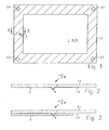
- the plastic disk 1 is made entirely of a transparent plastic material and has, for example, a substantially rectangular contour.
- the viewer in Fig. 1 facing side of the plastic disk 1 is the back of the plastic disk 1.
- the sprue rib 4 is located on an optical top surface of the back 1.2 of the plastic disc 1 and preferably in the region near the edge thereof.
- the optical surface on the front side 1.1 of the plastic disk is - in particular also in the area opposite the sprue rib 4 - exposed (optically not covered) and thus visible to the viewer B.
- a so-called black edge 2 is injection-molded onto the plastic disk 1.
- the black edge 2 rotates the plastic disc 1 in the manner of a closed frame.
- the black edge 2 is realized by molding a plastic compound of low or non-existent transparency to the already finished transparent plastic disk 1.
- the position of the sprue rib 4 is selected such that the sprue rib 4 is located in a region within the black border 2.
- the thickness of the transparent plastic disk 1 may be for example 4 mm.
- the side lengths of the transparent plastic sheet 1 are in the usual dimensions for motor vehicle windows or sunroofs, i. As a rule, they are larger by more than a factor of 50 than the thickness of the plastic disk 1.
- Integral fastening elements 2.1, 2.2, 2.3, 2.4 can be integrally formed on the black edge 2, which serve for fastening the plastic disk 1 to a sliding mechanism, for example.
- the sprue rib 4 is clearly recognizable both from the rear side 1.2 and the front side 1.1 of the plastic pane 1.
- the separation of the sprue rib does not change this, as the interface still remains clearly visible from the front side 1.1 of the plastic disk 1 (i.e., looking through the disk).
- a direct injection method is used, for example, with hot runner gate valve closure for the production of the plastic disc 1 and the inevitable sprue rib 4 back covered by the black border 2.
- the FIGS. 2 and 3 show two variants for this.
- the thickness of the black edge 2 is less than the height of the sprue rib 4 over the back side 1.2 of the plastic disk 1.
- the sprue rib is encased by the black edge 2. This has the consequence that from the back no light falls on the sprue rib 4.
- the sprue rib 4 is barely recognizable or can no longer be seen.
- a second variant consists in accordance with Fig. 3 completely embed the sprue rib 4 in the black border 2.
- the contour of the sprue rib 4 disappears in the black border 2 and is no longer recognizable even from the rear side of the plastic pane 1.
- the black border 2 which is used for example in sunroofs of motor vehicles, thus solves the problem of concealing the sprue rib 4 when viewing the plastic pane 1 from the visible side (front side 1.1).
- the strength of the black border 2 in Fig. 2 For example, 2 mm and the strength of the black border 2 in the Fig. 3 eg 5 mm.
- a separation of the sprue rib 4 is not necessary for optical reasons, but can be made if e.g. Construction height restrictions make this appear desirable.
- the black border 2 conceals the separation point.
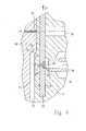
- Fig. 4 shows a section of a tool for producing the plastic disc 1 by means of a direct Anspritzvons.
- this consists of two mold plates 10, 11, between which a cavity 12 is formed.
- the cavity 12 is passed through a recess 13 in the mold plate 10 (so-called Matrizenformplatte) and realized by a projection 14 (so-called mold core) in the mold plate 11 (so-called mold core plate).
- the cavity 12 is bounded by a dipping edge gap 15, which is defined by a die-side dipping edge 16 and a core-side dipping edge 17.
- the plastic feed unit 18 comprises a so-called hot runner 19 with a central hot runner bore 20, via which liquid plastic (not shown) from a plastic source in the direction of the cavity 12 is passed.
- the hot runner 19 is always maintained in the injection molding at a temperature which is above the solidification temperature of the plastic mass, so that in the hot runner 19 plastic is always present in liquid form.
- the hot runner bore 20 opens into a groove 21 incorporated in the mold core plate 11, in which a locking slide 22 is slidably received.
- the gate valve 22 is oriented in a plane perpendicular to the hot runner bore 20 and in the direction of arrow P from the in Fig. 4 shown position are pulled out of the groove 21.
- the locking slide 22 has a passage 23, which in the in Fig. 2 shown position of the locking slide 22 connects to the hot runner bore 20.
- An opening provided in the mold core plate 11 runner 24 connects the passageway 23 in the gate valve with the cavity 12th
- liquid plastic compound is conducted from the hot runner bore 20 via the passageway 23 and the runner 24 into the cavity 12.
- the blocking slide 22 is displaced in the direction of the arrow P.
- a plastic residue, which in the passageway 23 remains and solidifies, is ejected via an ejector 25 and provided in the mold core plate 11 ejector bore 26.
- the plastic compound contained in the sprue channel 24 hardens and forms the integrally formed on the plastic disc 1 Angusrippe 4th
- a sprue rib 4 in the case of a locking slide closure
- another surface defect in the case of a needle jet seal, an impression point of the nozzle needle
- the presence of such a surface defect (gate mark) in the region of an optical surface of the plastic disk can, as already mentioned, only be achieved by the film gate - i. an indirect injection process - be avoided, which binds laterally in the region of the dipping edge gap 15.
- the already mentioned disadvantages high loss of material, separation of the sprue extension
- the mold core plate 11 against another mold core plate (so-called Anspritz-shaped plate - is in Fig. 4 not shown) exchanged.
- the molded plastic disk 1 remains in the female mold plate 10.
- the molded core plate (not shown) is shaped similar to the mold core plate 11, however, the mold core 14 has a recessed portion located at the edge, the shape of which is complementary to the shape of the second component to be molded (FIG. eg black border 2). Via a plastic feed opening into this recessed portion, the plastic compound for injection molding of the second component into the between the recessed portion of the mold core of the injection molding plate and the surface of the plastic disc 1 occurring Anspritzkavmaschine initiated.
- the invention provides a transparent flat plastic Fernstencalculation a motor vehicle, which in a simple and cost-effective production by a direct injection method despite the presence of a sprue (or other caused by the spraying of the transparent plastic molding visible Anguss spot) on an optical Surface still meets the required demands on the freedom of optical inhomogeneities on optical surfaces.
Landscapes
- Engineering & Computer Science (AREA)
- Mechanical Engineering (AREA)
- Manufacturing & Machinery (AREA)
- Injection Moulding Of Plastics Or The Like (AREA)
- Moulds For Moulding Plastics Or The Like (AREA)
Description
- Die Erfindung betrifft ein transparente flächige Kunststoff-Fernstenscheibe eines Kraftfahrzeugs, ein Verfahren zur Herstellung derselben und die Verwendung derselben.
- Flächige transparente optische Formteile, wie Kraftfahrzeug-Verscheibungen, wurden bisher in der Regel aus Glas hergestellt. Aufgrund des geringeren Gewichts, der höheren Schlagzähigkeit und vor allem der erhöhten Design-Freiheit erlangen in jüngster Zeit optische Formteile aus Kunststoff eine zunehmende Bedeutung.
- Die Herstellung von großflächigen, transparenten Kunststoff-Formteilen mit geringer Wandstärke ist aufgrund der hohen erforderlichen Spritzdrücke technologisch schwierig. Hinzu kommt, dass bei transparenten Formteilen erhöhte Qualitätsanforderungen im Hinblick auf die optische Güte (Schlierenfreiheit, Spannungsfreiheit, Vermeidung von Einfall) bestehen, deren Einhaltung zusätzliche Herausforderungen mit sich bringt. Eine weitere Schwierigkeit, die bei der Herstellung großflächiger Kunststoff-Formteile zu überwinden ist, betrifft die Problematik der Kunststoffzuführung. In vielen Fällen ist eine randseitige Zuführung der Kunststoffmasse erforderlich, um ein Formteil mit optisch einwandfreien Oberflächen, d.h. ohne störende Anguss-Stellen, zu erzielen.
- Um Anguss-Stellen an optischen Oberflächen eines transparenten flächigen Kunststoff-Formteils zu vermeiden, wird das sogenannte Filmanguss-Verfahren eingesetzt. Bei diesem Verfahren erfolgt die Anspritzung des Formteils seitlich außerhalb des Formhohlraums, in welchem das Formteil hergestellt wird (sogenannte "indirekte Anspritzung"). Zwischen dem Anspritzpunkt und einem als Angussverlängerung ausgebildeten Randbereich des Formhohlraums ist eine sogenannte Filmplatte vorgesehen, in welcher Angusskanäle eingearbeitet sind, die sich ausgehend vom Anspritzpunkt über die Filmplatte verteilen und die Filmplatte über die gesamte Breite des Formhohlraums an diesen anbinden. Nach dem Erkalten der Kunststoffmasse in dem Formhohlraum wird das Formteil aus dem geöffneten Werkzeug entnommen, wobei die über die Filmplatte zugeführte Kunststoffmasse als Angusskaltkanäle integral in seitlicher Verlängerung des Formteils an diesem angeformt sind (sogenannte Angussverlängerung).
- Aufgrund der bei der Filmanguss-Technik vorgenommenen seitlichen bzw. randseitigen Kunststoffzuführung treten keine Anguss-Stellen an optischen Oberflächen auf. Nachteilig ist jedoch, dass die Angussverlängerung mit den Angusskaltkanälen von dem Formteil abgetrennt werden muss, wodurch ein zusätzlicher Arbeitsschritt benötigt wird. Ferner fällt durch das Abtrennen der Angussverlängerung ein relativ großer Materialverlust an.
- Direkteinspritz-Verfahren, bei welchen die Kunststoffmasse z.B. über eine Nadelventil-Düse oder einen Sperrschieber direkt aus dem Heißkanal in den Formhohlraum eingebracht wird, werden bereits für die Herstellung von nicht optischen Formteilen eingesetzt. Anders als bei der Filmanguss-Technik erfolgt die Kunststoffzuführung nicht seitlich in Richtung der Flächenebene des Formteils, sondern an einer Oberfläche des Formteils. Der Hauptvorteil der Direkteinspritzung besteht darin, dass die beim Filmanguss-Standardverfahren erforderliche Angussabtrennung sowie die damit verbundenen Materialmehrkosten entfallen. Allerdings ergibt sich im Fall der Herstellung von optischen Formteilen das Problem, dass die Anspritzung an einer optischen Oberfläche des Formteils erfolgen muss und infolgedessen die (an einer Sichtfläche, üblicherweise an der Rückseite des flächigen Formteils) auftretende Anguss-Stelle durch das transparente Formteil hindurch sichtbar bleibt. Daher wurden Direkt-Einspritzverfahren bisher her nicht für die Herstellung optischer Formteile in Betracht gezogen.
- In der Schrift
US 5,922,369 ist die Herstellung eines zweikomponentigen Kunststoff-Formteils aus einer unteren weißen Schicht und einer oberen roten Schicht beschrieben. Die untere weiße Schicht wird durch ein Direkt-Einspritzverfahren hergestellt, wobei eine Anguss-Stelle auf der dem Betrachter zugewandten Oberfläche verbleibt. Diese Anguss-Stelle wird durch die obere rote Schicht abgedeckt und dadurch gegenüber dem Betrachter versteckt. - Die Schrift
WO 99/44802 - Der vorliegenden Erfindung liegt die Aufgabe zugrunde, eine transparente flächige Kunststoff-Fensterscheibe eines kraftfahrzeugs mit einwandfreien optischen Eigenschaften und geringen Materialkosten zu schaffen. Ferner ist es Aufgab der Erfindung, ein Verfahren zur Herstellung eine solchen Kunststoff-Fensterscheibe anzugeben.
- Die der Erfindung zugrunde liegende Aufgabenstellung wird durch die Merkmale der unabhängigen Ansprüche 1, 14, und 19 gelöst. Vorteilhafte Ausgestaltungen und Weiterbildungen der Erfindung sind in den Unteransprüchen angegeben.
- Durch die Abdeckung der Anguss-Stelle durch das Abdeckmaterial wird erreicht, dass die Anguss-Stelle "rückseitig verschattet" wird, d.h. wesentlich weniger Durchgangslicht als ohne Abdeckmaterial für die Wahrnehmung der Anguss-Stelle zur Verfügung steht. Dadurch wird erreicht, dass die Anguss-Stelle für den Betrachter durch die transparente Kunststoff-Fensterscheibe hindurch praktisch nicht mehr oder nur noch bei sehr genauer Betrachtung erkennbar ist. Da es bei Kunststoff-Fensterscheiben in vielen Fällen möglich und häufig sogar wünschenswert ist, eine randseitige, rahmenartige Abdeckung anzubringen, ist die erfindungsgemäße Lösung in vielen Anwendungsfällen einsetzbar. Hinzu kommt, dass Kunststoff-Fensterscheiben in ihrem Zentralbereich in der Regel wesentlich genauer betrachtet und wahrgenommen werden, als in Randbereichen. Da sich die Anguss-Stelle in bevorzugter Weise im randnahen Bereich der optischen Oberfläche befindet, tritt insofern noch ein physiologischer Effekt (höhere Wahrnehmungsschwelle), der die Wahrnehmung der Angussrippe bzw. Abtrennstelle erschwert, hinzu. Durch die erfindungsgemäße Abdeckung der Anguss-Stelle wird erreicht, dass ein Direkt-Anspritzverfahren zur Herstellung der Kunststoff-Fensterscheibe ermöglicht wird.
- Vorzugsweise handelt es sich bei der Anguss-Stelle um eine von der optischen Oberfläche wegstehende Angussrippe oder um eine Abtrennstelle einer solchen von der optischen Oberfläche abgetrennten Angussrippe. Eine Angussrippe tritt beispielsweise auf, wenn ein Sperrverschieber-Heißkanalverschluss für die Spritzgieß-Fertigung der flächigen Kunststoff-Fensterscheibe eingesetzt wird. Es ist jedoch auch möglich, dass die Anguss-Stelle eine andere Oberflächen-Inhomogenität darstellt. Z.B. wird bei der Verwendung eines Nadelventil-Verschlusses eines Heißkanals bei einem Direkt-Einspritzverfahren die Abdruckstelle der Nadel auf der optischen Oberfläche der flächigen Kunststoff-Fensterscheibe erzeugt.
- Vorzugsweise ist das Abdeckmaterial ein an die Kunststoff-Fensterscheibe angespritztes Kunststoffmaterial. Derartige Kunststoff-Fensterscheiben werden auch als 2K-Formteile (2K: zwei Komponenten) bezeichnet, da eine erste Kunststoffkomponente die transparente Kunststoff-Fensterscheibe und die zweite Kunststoffkomponente die Abdeckung bildet. Derartige 2K-Kunststoff-Fensterscheiben können kostengünstig in einer Spritzgießmaschine mit einem speziellen Plattenwender zum Anspritzen der zweiten Komponente an die bereits gefertigte erste Komponente hergestellt werden. Mittels der Erfindung können optische 2K-Kunststoff-Fensterscheiben nun ohne Einsatz der aufwändigen Filmanguss-Technik hergestellt werden. Der Vorteil der Verwendung eines angespritzten Kunststoffmaterials als Abdeckung besteht auch darin, dass durch das unter hoher Temperatur und hohem Druck erfolgende Anspritzen eine homogene Oberflächen-Verschmelzung zwischen der Anguss-Stelle und dem Kunststoffmaterial (Abdeckung) auftritt, wodurch eine minimale Wahrnehmbarkeit der Anguss-Stelle gewährleistet wird.
- Bei der Herstellung der Abdeckung durch ein angespritztes Kunststoffmaterial kennzeichnet sich eine erste vorteilhafte Ausführungsvariante dadurch, dass wenigstens eine von der optischen Oberfläche wegstehende Angussrippe von dem Kunststoffmaterial freistehend ummantelt ist. Die Angussrippe steht in diesem Fall weiterhin über ihre Umgebung vor, die erfindungsgemäße Abdeckung der Angussrippe wird lediglich mittels eines dünnen Überzugs der Angussrippe mit Abdeckmaterial bewerkstelligt. Vorteilhaft ist, dass für diese Maßnahme nur wenig Abdeckmaterial benötigt wird.
- Nach einer alternativen Ausführungsvariante kann vorgesehen sein, dass wenigstens eine von der optischen Oberfläche wegstehende Angussrippe vollständig in dem Kunststoffmaterial eingebettet ist. In diesem Fall ist die Angussrippe vollständig in dem Kunststoffmaterial verschwunden, d.h. auch von der Seite, auf welcher das Kunststoff-Abdeckmaterial aufgebracht wurde, nicht mehr zu erkennen. Eine solche Lösung bietet sich insbesondere dann an, wenn aus konstruktiven Gründen ein stärkerer Rand bzw. Rahmen aus Abdeckmaterial an der flächigen Kunststoff-Fensterscheibe angebracht werden soll.
- Eine andere Möglichkeit besteht darin, dass das Abdeckmaterial ein auf die Kunststoff-Fensterscheibe aufgetragener Lack ist. Eine von der optischen Oberfläche der Kunststoff-Fensterscheibe wegstehende Angussrippe wird in diesem Fall von dem Lack ummantelt.
- Eine weitere vorteilhafte Maßnahme kennzeichnet sich dadurch, dass die Kunststoff-Fensterscheibe eine Tönung, z.B. eine Farbtönung, aufweist. Schon eine relativ geringe Tönung, die die Transparenz der Kunststoff-Fensterscheibe in kaum wahrnehmbarer Weise vermindert, verstärkt im Bereich der Anguss-Stelle die kaschierende Wirkung des Abdeckmaterials erheblich.
- In Bezug auf das Abdeckmaterial werden besonders gute Ergebnisse mit einem vollständig undurchsichtigen Abdeckmaterial erreicht, da in diesem Fall eine "Rückseitenbeleuchtung" der Anguss-Stelle vollständig unterbunden ist.
- Ferner ist es vorteilhaft, ein schwarzes Abdeckmaterial zu verwenden, da auf diese Weise eine Minimierung des für die Wahrnehmung der Anguss-Stelle (z.B. Angussrippe bzw. der Abtrennstelle derselben oder Nadel-Abdruckstelle) zur Verfügung stehenden Reflektionslichtes erreicht wird.
- Bei der Kunststoff-Fensterscheibe können häufig eine Vielzahl der genannten Maßnahmen (Anbringen eines 2K-Schwarzrandes mit ausreichender Wandstärke sowie eine Tönung der Scheibe) kombiniert werden, wodurch in der Praxis eine nahezu perfekte Kaschierung des durch die Anguss-Stelle bewirkten optischen Defekts ermöglicht wird. Das kostenintensive Filmanguss-Verfahren zur Scheibenherstellung kann auf diese Weise vermieden werden.
- Zur Herstellung der Kunststoff-Fensterscheibe wird zunächst die Kunststoff-Fensterscheibe mittels eines Direkt-Einspritzverfahrens durch Spritzgießen hergestellt, wodurch mindestens eine Anguss-Stelle an einer optischen Oberfläche der Kunststoff-Fensterscheibe auftritt. Diese sichtbare Anguss-Stelle wird mit einem Abdeckmaterial geringerer Transparenz als die Kunststoff-Fensterscheibe bedeckt. Durch die erfindungsgemäße Kombination eines Direkt-Einspritzverfahrens und der Abdeckung der dabei unvermeidlich entstehenden Anguss-Stelle zum Zwecke der Kaschierung derselben können einwandfreie Kunststoff-Fensterscheiben auf kostengünstigem Wege gefertigt werden.
- Mit optischer Oberfläche ist bei einer flächigen, transparenten Kunststoff-Fensterscheibe die Ober- bzw. Unterfläche der Fensterscheibe, nicht jedoch die Seitenrandfläche, gemeint. Die optische Oberfläche, an welcher sich die Anguss-Stelle befindet, ist dabei die für einen Betrachter in Blickrichtung hintere (rückseitige) Oberfläche der Kunststoff-Fensterscheibe.
- Die Erfindung wird nachfolgend anhand eines Ausführungsbeispiels sowie Varianten desselben unter Bezugnahme auf die Zeichnungen näher beschrieben; in diesen zeigt:
- Fig. 1
- eine transparente Kunststoffscheibe mit einem an die Rückseite der Scheibe angespritzten Kunststoffrand in Draufsicht auf die Rückseite der Kunststoffscheibe;
- Fig. 2
- eine Teilschnittansicht der in
Fig. 1 dargestellten Kunststoffscheibe entlang der Linie X-X gemäß einer ersten Variante der Erfindung; - Fig. 3
- eine Teilschnittansicht der in
Fig. 1 dargestellten Kunststoffscheibe entlang der Linie X-X gemäß einer zweiten Variante der Erfindung; und - Fig. 4
- eine Schnittdarstellung eines Abschnitts eines Spritzgusswerkzeugs zur Herstellung der flächigen Kunststoffscheibe und zur Erläuterung eines Direkt-Anspritzverfahrens.
- Die Kunststoffscheibe 1 besteht vollflächig aus einem transparenten Kunststoffmaterial und weist z.B. eine im Wesentlichen rechteckige Kontur auf. Die dem Betrachter in
Fig. 1 zugewandte Seite der Kunststoffscheibe 1 ist die Rückseite der Kunststoffscheibe 1. Wie im Folgenden noch näher erläutert wird und in denFiguren 2 und 3 in Schnittdarstellung erkennbar ist, steht an dieser Rückseite eine Angussrippe 4 vor. Die Angussrippe 4 befindet sich an einer optischen Ober-
fläche der Rückseite 1.2 der Kunststoffscheibe 1 und vorzugsweise im randnahen Bereich derselben. Die optische Oberfläche an der Vorderseite 1.1 der Kunststoffscheibe ist - insbesondere auch im Bereich gegenüberliegend der Angussrippe 4 - freiliegend (optisch nicht abgedeckt) und somit für den Betrachter B sichtbar. - Rückseitig ist an die Kunststoffscheibe 1 ein sogenannter Schwarzrand 2 angespritzt. Der Schwarzrand 2 umläuft die Kunststoffscheibe 1 in Art eines geschlossenen Rahmens. Der Schwarzrand 2 wird durch Anspritzen einer Kunststoffmasse geringer bzw. nicht vorhandener Transparenz an die bereits fertiggestellte transparente Kunststoffscheibe 1 realisiert. Die Lage der Angussrippe 4 wird so gewählt, dass sich die Angussrippe 4 in einem Bereich innerhalb des Schwarzrandes 2 befindet.
- Die Dicke der transparenten Kunststoffscheibe 1 kann beispielsweise 4 mm betragen. Die Seitenlängen der transparenten Kunststoffscheibe 1 bewegen sich in den üblichen Dimensionen für Kfz-Fenster oder Schiebedächer, d.h. sind in der Regel um mehr als den Faktor 50 größer als die Dicke der Kunststoffscheibe 1. An den Schwarzrand 2 können integrale Befestigungselemente 2.1, 2.2, 2.3, 2.4 angeformt sein, welche zur Befestigung der Kunststoffscheibe 1 beispielsweise an einer Schiebemechanik dienen.
- Ohne den Schwarzrand 2 ist die Angussrippe 4 sowohl von der Rückseite 1.2 als auch der Vorderseite 1.1 der Kunststoffscheibe 1 deutlich erkennbar. Das Abtrennen der Angussrippe ändert daran nichts, da die Trennfläche weiterhin deutlich auch von der Vorderseite 1.1 der Kunststoffscheibe 1 (d.h. in Durchsicht durch die Scheibe) erkennbar bleibt.
- Erfindungsgemäß wird zur Herstellung der Kunststoffscheibe 1 ein Direkt-Einspritzverfahren z.B. mit Heißkanal-Sperrschieberverschluss eingesetzt und die dabei unvermeidliche Angussrippe 4 rückseitig von dem Schwarzrand 2 abgedeckt. Die
Figuren 2 und 3 zeigen hierfür zwei Varianten. InFig. 2 ist die Stärke des Schwarzrandes 2 geringer als die Höhe der Angussrippe 4 über der Rückseite 1.2 der Kunststoffscheibe 1. In diesem Fall wird die Angussrippe von dem Schwarzrand 2 ummantelt. Dies hat zur Folge, dass von der Rückseite kein Licht mehr auf die Angussrippe 4 fällt. Für den Betrachter B, welcher die Vorderseite 1.1 der transparenten Kunststoffscheibe 1 betrachtet, ist die Angussrippe 4 nunmehr kaum oder gar nicht mehr zu erkennen. - Eine zweite Variante besteht darin, gemäß
Fig. 3 die Angussrippe 4 vollständig in den Schwarzrand 2 einzubetten. In diesem Fall verschwindet die Kontur der Angussrippe 4 in dem Schwarzrand 2 und ist auch von der Rückseite der Kunststoffscheibe 1 her nicht mehr erkennbar. Der Schwarzrand 2, der z.B. bei Schiebedächern von Kraftfahrzeugen verwendet wird, löst damit zugleich das Problem der Kaschierung der Angussrippe 4 beim Betrachten der Kunststoffscheibe 1 von der Sichtseite (Vorderseite 1.1) her. - Die Stärke des Schwarzrandes 2 in
Fig. 2 kann z.B. 2 mm und die Stärke des Schwarzrandes 2 in derFig. 3 z.B. 5 mm betragen. - Eine Abtrennung der Angussrippe 4 ist aus optischen Gründen nicht erforderlich, kann jedoch vorgenommen werden, sofern z.B. Bauhöhen-Beschränkungen dies wünschenswert erscheinen lassen. In diesem Fall kaschiert der Schwarzrand 2 die Abtrennstelle.
-
Fig. 4 zeigt einen Ausschnitt aus einem Werkzeug zur Herstellung der Kunststoffscheibe 1 mittels eines Direkt-Anspritzverfahrens. Gemäß der üblichen Bauweise eines Spritzgusswerkzeugs besteht dieses aus zwei Formplatten 10, 11, zwischen denen eine Kavität 12 ausgebildet ist. Die Kavität 12 wird durch eine Vertiefung 13 in der Formplatte 10 (sogenannte Matrizenformplatte) und durch einen Vorsprung 14 (sogenannter Formkern) in der Formplatte 11 (sogenannte Formkernplatte) realisiert. Die Kavität 12 wird durch einen Tauchkantenspalt 15 begrenzt, der durch eine matrizenseitige Tauchkante 16 und eine kernseitige Tauchkante 17 definiert ist. - Eine in der Formkernplatte 11 eingearbeitete Kunststoffzuführungs-Einheit 18 dient dazu, beim Befüllvorgang flüssige, transparente Kunststoffmasse in die Kavität 12 zur Herstellung der Kunststoffscheibe 1 einzuleiten. Die Kunststoffzuführungs-Einheit 18 umfasst einen sogenannten Heißkanal 19 mit einer zentralen Heißkanalbohrung 20, über welche flüssiger Kunststoff von einer Kunststoffquelle (nicht dargestellt) in Richtung zu der Kavität 12 geleitet wird. Der Heißkanal 19 wird im Spritzgießbetrieb stets auf einer Temperatur gehalten, die oberhalb der Verfestigungstemperatur der Kunststoffmasse liegt, so dass in dem Heißkanal 19 Kunststoff stets in flüssiger Form vorliegt.
- Die Heißkanalbohrung 20 mündet in eine in der Formkernplatte 11 eingearbeitete Nut 21, in welcher ein Sperrschieber 22 verschieblich geführt aufgenommen ist. Der Sperrschieber 22 ist in einer Ebene senkrecht zu der Heißkanalbohrung 20 orientiert und kann in Richtung des Pfeils P aus der in
Fig. 4 gezeigten Position aus der Nut 21 herausgezogen werden. - Der Sperrschieber 22 weist einen Durchtrittskanal 23 auf, welcher in der in
Fig. 2 gezeigten Position des Sperrschiebers 22 an die Heißkanalbohrung 20 anschließt. Ein in der Formkernplatte 11 vorgesehener Angusskanal 24 verbindet den Durchtrittskanal 23 im Sperrschieber mit der Kavität 12. - Beim Befüllvorgang wird flüssige Kunststoffmasse von der Heißkanalbohrung 20 über den Durchtrittskanal 23 und den Angusskanal 24 in die Kavität 12 geleitet. Sobald die Kavität 12 ausreichen gefüllt ist, wird der Sperrschieber 22 in Richtung des Pfeils P verschoben. Ein Kunststoffrest, welcher in dem Durchtrittskanal 23 zurückbleibt und sich verfestigt, wird über einen Auswerfer 25 und eine in der Formkernplatte 11 vorgesehene Auswerferbohrung 26 ausgestoßen. Gleichzeitig erhärtet auch die in dem Angusskanal 24 enthaltene Kunststoffmasse und bildet die integral an der Kunststoffscheibe 1 angeformte Angusrippe 4.
- Es wird darauf hingewiesen, dass bei einem Direkt-Einspritzverfahren auch andere Schließmechaniken (z.B. Nadeldüsen-Verschlüsse usw.) zum Einsatz kommen können. Unvermeidlicherweise bleibt jedoch stets eine Angussrippe 4 (bei einem Sperrschieber-Verschluss) oder ein anderer Oberflächen-Defekt (bei einem Nadeldüsen-Verschluss eine Abdruckstelle der Düsennadel) im Bereich einer optischen Oberfläche der Kunststoffscheibe 1 zurück. Das Vorhandensein eines solchen Oberflächen-Defekts (Anguss-Stelle) im Bereich einer optischen Oberfläche der Kunststoffscheibe kann, wie bereits erwähnt, nur durch den Filmanguss - d.h. ein indirektes Einspritzverfahren - vermieden werden, welcher seitlich im Bereich des Tauchkantenspalts 15 anbindet. Dabei müssen jedoch die bereits erwähnten Nachteile (hoher Materialverlust, Abtrennung der Angussverlängerung) in Kauf genommen werden.
- Zum Anspritzen der zweiten Komponente an die Kunststoffscheibe 1 wird die Formkernplatte 11 gegen eine andere Formkernplatte (sogenannte Anspritz-Formplatte - ist in
Fig. 4 nicht dargestellt) ausgetauscht. Die verfestigte Kunststoffscheibe 1 verbleibt in der Matrizenformplatte 10. Die Anspritz-Formkernplatte (nicht dargestellt) ist ähnlich wie die Formkernplatte 11 gestaltet, jedoch weist der Formkern 14 einen randseitig angeordneten, vertieften Abschnitt auf, dessen Form komplementär zu der Form der anzuspritzenden zweiten Komponente (z.B. Schwarzrands 2) ist. Über eine in diesen vertieften Abschnitt mündende Kunststoffzuführung wird die Kunststoffmasse zum Anspritzen der zweiten Komponente in die zwischen dem vertieften Abschnitt des Formkerns der Anspritz-Formplatte und der Oberfläche der Kunststoffscheibe 1 auftretenden Anspritzkavität eingeleitet. - Zusammenfassend schafft die Erfindung ein transparente flächige Kunststoff-Fernstenscheibe eines Kraftfahrzeugs, welche bei einfacher und kostengünstiger Herstellung mittels eines Direkt-Einspritzverfahrens trotz des Vorhandenseins einer Angussrippe (oder einer anderen durch das Spritzen des transparenten Kunststoff-Formteils bewirkten sichtbaren Anguss-Stelle) an einer optischen Oberfläche dennoch die geforderten Ansprüche an die Freiheit von optischen Inhomogenitäten an optischen Oberflächen einhält.
Claims (19)
- Transparente flächige Kunststoff-Fensterscheibe eines Kraftfahrzeugs, mit mindestens einer sich an einer optischen Oberfläche (1.2) der Kunststoff-Fensterscheibe (1) befindenden, infolge der Anwendung eines Direkt-Einspritzverfahrens bei der Herstellung der Kunststoff-Fensterscheibe (1) auftretenden Anguss-Stelle (4), wobei die Anguss-Stelle (4) von einem Abdeckmaterial (2) geringerer Transparenz als die Kunststoff-Fensterscheibe (1) bedeckt ist.
- Transparente flächige Kunststoff-Fensterscheibe eines Kraftfahrzeugs nach Anspruch 1,
dadurch gekennzeichnet,
dass es sich bei der Anguss-Stelle um eine von der optischen Oberfläche (1.2) wegstehende Angussrippe (4) oder um eine Abtrennstelle einer solchen von der optischen Oberfläche (1.2) abgetrennten Angussrippe (4) oder um eine Abdruckstelle einer Nadel eines Nadelventil-Verschlusses handelt. - Transparente flächige Kunststoff-Fensterscheibe eines Kraftfahrzeugs nach Anspruch 1 oder 2,
dadurch gekennzeichnet,
dass sich die Anguss-Stelle (4) im randnahen Bereich der optischen Oberfläche (1.2) befindet. - Transparente flächige Kunststoff-Fensterscheibe eines Kraftfahrzeugs nach einem der vorhergehenden Ansprüche,
dadurch gekennzeichnet,
dass das Abdeckmaterial ein an der Kunststoff-Fensterscheibe (1) angespritztes Kunststoffmaterial (2) ist. - Transparente flächige Kunststoff-Fensterscheibe eines Kraftfahrzeugs nach Anspruch 4,
dadurch gekennzeichnet,
dass wenigstens eine von der optischen Oberfläche (1.2) wegstehende Angussrippe (4) von dem Kunststoffmaterial (2) freistehend ummantelt ist. - Transparente flächige Kunststoff-Fensterscheibe eines Kraftfahrzeugs nach Anspruch 4,
dadurch gekennzeichnet,
dass wenigstens eine von der optischen Oberfläche (1.2) wegstehende Angussrippe (4) vollständig in dem Kunststoffmaterial (2) eingebettet ist. - Transparente flächige Kunststoff-Fensterscheibe eines Kraftfahrzeugs nach einem der Ansprüche 1 bis 3,
dadurch gekennzeichnet,
dass das Abdeckmaterial (2) ein auf die Kunststoff-Fensterscheibe (1) aufgetragener Lack ist. - Transparente flächige Kunststoff-Fensterscheibe eines Kraftfahrzeugs nach Anspruch 7,
dadurch gekennzeichnet,
dass wenigstens eine von der optischen Oberfläche (1.2) wegstehende Angussrippe (4) von dem Lack ummantelte ist. - Transparente flächige Kunststoff-Fensterscheibe eines Kraftfahrzeugs nach einem der vorhergehenden Ansprüche,
dadurch gekennzeichnet,
dass die Kunststoff-Fensterscheibe (1) eine Tönung aufweist. - Transparente flächige Kunststoff-Fensterscheibe eines Kraftfahrzeugs nach einem der vorhergehenden Ansprüche,
dadurch gekennzeichnet,
dass das Abdeckmaterial (2) vollständig undurchsichtig ist. - Transparente flächige Kunststoff-Fensterscheibe eines Kraftfahrzeugs nach einem der vorhergehenden Ansprüche,
dadurch gekennzeichnet,
dass das Abdeckmaterial (2) schwarz ist. - Transparente flächige Kunststoff-Fensterscheibe eines Kraftfahrzeugs nach einem der vorhergehenden Ansprüche,
dadurch gekennzeichnet,
dass das Abdeckmaterial (2) die Kunststoff-Fensterscheibe (1) in Art eines Rahmens geschlossen umläuft. - Transparente flächige Kunststoff-Fensterscheibe eines Kraftfahrzeugs nach einem der vorhergehenden Ansprüche,
dadurch gekennzeichnet,
dass die der optischen Oberfläche (1.2) gegenüberliegende optische Oberfläche (1.1) der Kunststoff-Fensterscheibe (1) eine Sichtfläche der Kunststoff-Fensterscheibe (1) ist. - Verfahren zur Herstellung einer transparenten flächigen Kunststoff-Fensterscheibe eines Kraftfahrzeugs, mit den Schritten:- Spritzgießen der Kunststoff-Fensterscheibe (1) mittels eines Direkt-Einspritzverfahrens, bei dem mindestens eine sich an einer optischen Oberfläche (1.2) der Kunststoff-Fensterscheibe (1) befindende Anguss-Stelle (4) auftritt; und- Bedecken der Anguss-Stelle (4) mit einem Abdeckmaterial (2) geringerer Transparenz als die Kunststoff-Fensterscheibe (1) .
- Verfahren nach Anspruch 14,
dadurch gekennzeichnet,
dass bei dem Direkt-Einspritzverfahren die Kunststoffmasse zur Herstellung der Kunststoff-Fensterscheibe (1) über einen Einspritzkanal mit Sperrschieberverschluss (22) oder Nadelventil-Verschluss einem Formhohlraum zugeführt wird. - Verfahren nach einem der Ansprüche 14 oder 15,
dadurch gekennzeichnet,
dass zum Bedecken der Anguss-Stelle (4) ein Abdeckmaterial (2) aus Kunststoff an die Kunststoff-Fensterscheibe (1) angespritzt wird. - Verfahren nach Anspruch 14 bis 16,
dadurch gekennzeichnet,
dass das Abdeckmaterial (2) vollständig undurchsichtig ist. - Verfahren nach Anspruch 14 bis 17,
dadurch gekennzeichnet,
dass das Abdeckmaterial (2) schwarz ist. - Verwendung der transparenten flächigen Kunststoff-Fensterscheibe eines Kraftfahrzeugs nach einem der Ansprüche 1 bis 12 derart, dass die der optischen Oberfläche (1.2) gegenüberliegende optische Oberfläche (1.1) der Kunststoff-Fensterscheibe (1) als Sichtseite verwendet wird.
Applications Claiming Priority (4)
| Application Number | Priority Date | Filing Date | Title |
|---|---|---|---|
| DE102004002012 | 2004-01-14 | ||
| DE200410002012 DE102004002012B4 (de) | 2004-01-14 | 2004-01-14 | Verfahren und Vorrichtung zum Einbringen von Kunststoffmasse in ein Spritzgusswerkzeug zur Herstellung flächiger Kunststoffteile |
| DE200420003468 DE202004003468U1 (de) | 2004-03-05 | 2004-03-05 | Transparentes flächiges Kunststoff-Formteil mit kaschierter Anguss-Stelle |
| DE202004003468U | 2004-03-05 |
Publications (2)
| Publication Number | Publication Date |
|---|---|
| EP1555106A1 EP1555106A1 (de) | 2005-07-20 |
| EP1555106B1 true EP1555106B1 (de) | 2009-08-05 |
Family
ID=34621429
Family Applications (1)
| Application Number | Title | Priority Date | Filing Date |
|---|---|---|---|
| EP05000727A Revoked EP1555106B1 (de) | 2004-01-14 | 2005-01-14 | Transparente flächige Kunststoff-Fensterscheibe eines Kraftfahrzeugs mit kaschierter Anguss-Stelle , Verfahren zur Herstellung derselben und Verwendung derselben |
Country Status (3)
| Country | Link |
|---|---|
| US (1) | US8173244B2 (de) |
| EP (1) | EP1555106B1 (de) |
| DE (1) | DE502005007821D1 (de) |
Cited By (2)
| Publication number | Priority date | Publication date | Assignee | Title |
|---|---|---|---|---|
| US8173244B2 (en) | 2004-01-14 | 2012-05-08 | Franz Josef Summerer | Transparent sheet-like shaped plastic part with concealed sprue mark, and process for producing it |
| DE102015017197B4 (de) | 2015-12-16 | 2023-04-20 | Roof Systems Germany Gmbh | Verfahren und Werkzeug zum Herstellen eines Fahrzeugdachglaselements |
Families Citing this family (8)
| Publication number | Priority date | Publication date | Assignee | Title |
|---|---|---|---|---|
| DE102006022921B4 (de) * | 2006-05-15 | 2008-02-07 | Webasto Ag | Fahrzeug-Dachteil aus wenigstens zwei Kunststoffschichten und Verfahren zum Herstellen eines solchen Fahrzeug-Dachteils |
| DE102008030823A1 (de) | 2008-06-30 | 2010-01-14 | Franz Josef Summerer | Vorrichtung und Verfahren zum Fertigen von Kunststoffbauteilen |
| WO2012015936A1 (en) | 2010-07-27 | 2012-02-02 | Agc Automative Americas R&D Inc. | Window assembly having a primer |
| WO2016209739A1 (en) * | 2015-06-26 | 2016-12-29 | Modern Packaging Llc | Overmolded low cost cutlery |
| US10335985B2 (en) | 2015-10-14 | 2019-07-02 | Capital One Services, Llc | Molded pocket in transaction card construction |
| KR20180082503A (ko) * | 2015-11-13 | 2018-07-18 | 엑사테크 엘.엘.씨. | 전도성 페이스트 및 이의 프린팅 방법 |
| JP6965871B2 (ja) * | 2018-12-26 | 2021-11-10 | 株式会社デンソー | 樹脂部品及びその製造方法 |
| EP3944947A1 (de) * | 2020-07-27 | 2022-02-02 | ZKW Group GmbH | Vorrichtung zur herstellung eines kunststoffbauteils |
Family Cites Families (29)
| Publication number | Priority date | Publication date | Assignee | Title |
|---|---|---|---|---|
| FR2301357A1 (fr) | 1975-02-24 | 1976-09-17 | Frankani Sa | Procede de |
| JPH0441502Y2 (de) * | 1986-02-04 | 1992-09-29 | ||
| JPH069850Y2 (ja) * | 1987-06-15 | 1994-03-16 | 日本板硝子株式会社 | 車両用窓ガラス |
| US4935184A (en) * | 1988-02-05 | 1990-06-19 | Primtec | Stabilized injection molding when using a common mold part with separate complimentary mold parts |
| JPH02227224A (ja) | 1989-02-28 | 1990-09-10 | Hashimoto Forming Ind Co Ltd | 合成樹脂製ウインドウの製造方法 |
| US5045268A (en) * | 1989-12-11 | 1991-09-03 | Sorensen Jens Ole | Cross-lamination injection molding |
| DE4038492A1 (de) | 1990-12-03 | 1992-06-04 | Peguform Werke Gmbh | Spritzkopf |
| JP2908176B2 (ja) * | 1993-05-18 | 1999-06-21 | 株式会社小糸製作所 | 車輌用灯具の合成樹脂製積層レンズ及びその成形方法 |
| US5413743A (en) * | 1993-05-20 | 1995-05-09 | General Motors Corporation | Method of making a lamp assembly |
| JP2826057B2 (ja) * | 1993-12-21 | 1998-11-18 | 株式会社小糸製作所 | 樹脂成形レンズ |
| JPH09267363A (ja) | 1996-03-29 | 1997-10-14 | Sanyo Electric Co Ltd | 前面キャビネット成形方法 |
| DE19655079C2 (de) | 1996-10-16 | 1999-08-12 | Volkswagen Ag | Fahrzeugscheibenmodul und Verfahren zu dessen Herstellung |
| US5882553A (en) * | 1997-06-09 | 1999-03-16 | Guide Corporation | Multi-color lens assembly injection molding process and apparatus |
| JPH1177740A (ja) * | 1997-09-17 | 1999-03-23 | Toyota Autom Loom Works Ltd | 樹脂成形品とその製造方法及び成形型 |
| AU738550C (en) | 1998-02-19 | 2003-01-09 | Husky Injection Molding Systems Ltd. | Valve gating apparatus and method for injection molding |
| DE19809753C2 (de) | 1998-03-06 | 2001-08-23 | Krauss Maffei Kunststofftech | Verfahren zum Herstellen einer Kunststoffscheibe |
| US6468458B1 (en) * | 1998-10-23 | 2002-10-22 | Textron Automotive Company Inc, | Method for forming a composite product |
| EP1131196B1 (de) * | 1998-11-20 | 2003-04-16 | Krauss-Maffei Kunststofftechnik GmbH | Verfahren zum herstellen von spritzgiessteilen in einer spritzgiessmaschine |
| WO2001028744A1 (en) | 1999-10-18 | 2001-04-26 | Exatec, Llc. | Molded plastic automotive window panel and process of providing masking border |
| JP4788026B2 (ja) | 2000-07-31 | 2011-10-05 | 旭硝子株式会社 | 車両用樹脂窓および車両用ドアパネル |
| US6808804B2 (en) * | 2000-08-18 | 2004-10-26 | Teijin Chemicals, Ltd. | Sheet-form layered structure with attractive appearance and utilization thereof |
| DE10047624A1 (de) | 2000-09-26 | 2002-04-25 | Dura Automotive Body & Glass | Verwendung eines Additives aus einem Emulgator und einem oder mehreren Inhibitoren zu einem Bad zum Entfernen von Schichten aus Nickel, Zinn, Blei oder Zinn-Blei von Oberflächen aus Kupfer oder Kupferlegierungen |
| DE10202246B8 (de) | 2002-01-21 | 2006-04-20 | Franz Josef Summerer | Vorrichtung und Verfahren zum Herstellen optischer Formteile aus Kunststoff |
| JP4017902B2 (ja) * | 2002-03-29 | 2007-12-05 | ポリマテック株式会社 | フィルム一体型キートップ |
| JP2004014423A (ja) | 2002-06-11 | 2004-01-15 | Koito Mfg Co Ltd | 車両用灯具 |
| DE10233679B4 (de) | 2002-07-24 | 2006-09-14 | Franz Josef Summerer | Vorrichtung zum Ausgleichen von beim Spritzprägen auftretenden Kippkräften und Verfahren zum Herstellen von Kunststoff-Formteilen |
| DE202004003468U1 (de) | 2004-03-05 | 2004-06-24 | Summerer, Franz Josef | Transparentes flächiges Kunststoff-Formteil mit kaschierter Anguss-Stelle |
| US8173244B2 (en) | 2004-01-14 | 2012-05-08 | Franz Josef Summerer | Transparent sheet-like shaped plastic part with concealed sprue mark, and process for producing it |
| DE102004002012B4 (de) | 2004-01-14 | 2006-03-23 | Franz Josef Summerer | Verfahren und Vorrichtung zum Einbringen von Kunststoffmasse in ein Spritzgusswerkzeug zur Herstellung flächiger Kunststoffteile |
-
2005
- 2005-01-13 US US11/034,199 patent/US8173244B2/en active Active
- 2005-01-14 DE DE502005007821T patent/DE502005007821D1/de not_active Expired - Lifetime
- 2005-01-14 EP EP05000727A patent/EP1555106B1/de not_active Revoked
Cited By (2)
| Publication number | Priority date | Publication date | Assignee | Title |
|---|---|---|---|---|
| US8173244B2 (en) | 2004-01-14 | 2012-05-08 | Franz Josef Summerer | Transparent sheet-like shaped plastic part with concealed sprue mark, and process for producing it |
| DE102015017197B4 (de) | 2015-12-16 | 2023-04-20 | Roof Systems Germany Gmbh | Verfahren und Werkzeug zum Herstellen eines Fahrzeugdachglaselements |
Also Published As
| Publication number | Publication date |
|---|---|
| US8173244B2 (en) | 2012-05-08 |
| EP1555106A1 (de) | 2005-07-20 |
| US20050158519A1 (en) | 2005-07-21 |
| DE502005007821D1 (de) | 2009-09-17 |
Similar Documents
| Publication | Publication Date | Title |
|---|---|---|
| DE102009022824A1 (de) | Spritzgussverfahren und Form für das Spritzgießen | |
| DE19842456A1 (de) | Formgegenstände aus Kunstharz | |
| DE69017208T2 (de) | Kunstharzfenster für Kraftfahrzeuge oder dergleichen. | |
| DE3820232A1 (de) | Verfahren zur herstellung einer kraftfahrzeugfensterscheibe und kraftfahrzeugfensterscheibe | |
| DE102010016350B4 (de) | Spritzpräge-Vorrichtung und-Verfahren zum Herstellen eines Formteils aus Kunststoff mit hinterspritzter Folie | |
| DE4237588A1 (de) | ||
| DE102008030823A1 (de) | Vorrichtung und Verfahren zum Fertigen von Kunststoffbauteilen | |
| DE102009003981B4 (de) | Vorrichtung und Verfahren zum Spritzgießen eines Kunststoff-Formteils | |
| DE202004003468U1 (de) | Transparentes flächiges Kunststoff-Formteil mit kaschierter Anguss-Stelle | |
| EP1555106A1 (de) | Transparentes flächiges Kunststoff-Formteil mit kaschierter Anguss-Stelle und Verfahren zur Herstellung desselben | |
| DE102007052197B4 (de) | Spritzgießverfahren zur Herstellung einer Abdeckscheibe einer Fahrzeugleuchte, Spritzgießwerkzeug hierfür und Abdeckscheibe einer Fahrzeugleuchte | |
| DE102009013789A1 (de) | Harz-Formteil, Verfahren zu deren Herstellung und Metallform zu dessen Herstellung | |
| EP3999339B1 (de) | Einen schichtaufbau aufweisendes sichtteil für ein bedienteil oder eine zierblende mit verbessertem schutz durch eine schutzlackbeschichtung | |
| DE102009015138A1 (de) | Spritzgießwerkzeug und Spritzgießverfahren zur Herstellung mehrteiliger Formteile | |
| DE19958316C1 (de) | Verfahren und Vorrichtung zum Herstellen eines Kunststoffformteils, welches mehrere Felder umfaßt | |
| DE10036969B4 (de) | Verfahren zur Herstellung einer Kunststoffscheibe und eine Kunststoffscheibe | |
| EP3181386B1 (de) | Fahrzeugdachglaselement, verfahren und werkzeug zum herstellen eines fahrzeugdachglaselements | |
| WO2012126907A1 (de) | Verfahren zur herstellung eines verbundbauteils | |
| DE10342360B4 (de) | Vorrichtung und Verfahren zum Fertigen eines zwei- oder mehrkomponentigen Kunstoff-Spritzgießteils mittels eines Prägeverfahrens | |
| DE102011056016A1 (de) | Verkleidungsblende | |
| DE19734686A1 (de) | Kunststoff-Formteil sowie Verfahren und Vorrichtung zu dessen Herstellung | |
| DE102010061556B4 (de) | Mehrkomponentiges flächiges Kunststoff-Sichtteil und Vorrichtung zur Herstellung desselben | |
| DE102013212445A1 (de) | Teilweise getöntes optisches Element und Verfahren zu seiner Herstellung | |
| EP1747922B1 (de) | Schiebefensterbaugruppe für ein Kraftfahrzeug | |
| DE102006049621A1 (de) | Transparentes, mehrlagiges Bauteil |
Legal Events
| Date | Code | Title | Description |
|---|---|---|---|
| PUAI | Public reference made under article 153(3) epc to a published international application that has entered the european phase |
Free format text: ORIGINAL CODE: 0009012 |
|
| 17P | Request for examination filed |
Effective date: 20050428 |
|
| AK | Designated contracting states |
Kind code of ref document: A1 Designated state(s): AT BE BG CH CY CZ DE DK EE ES FI FR GB GR HU IE IS IT LI LT LU MC NL PL PT RO SE SI SK TR |
|
| AX | Request for extension of the european patent |
Extension state: AL BA HR LV MK YU |
|
| AKX | Designation fees paid |
Designated state(s): DE |
|
| 17Q | First examination report despatched |
Effective date: 20060314 |
|
| 17Q | First examination report despatched |
Effective date: 20060314 |
|
| TPAC | Observations by third parties |
Free format text: ORIGINAL CODE: EPIDOSNTIPA |
|
| RTI1 | Title (correction) |
Free format text: TRANSPARENT FLAT PLASTIC WINDOW OF A VEHICLE WITH LINED INJECTION MARK, METHOD OF PRODUCTION AND USE THEREOF |
|
| GRAP | Despatch of communication of intention to grant a patent |
Free format text: ORIGINAL CODE: EPIDOSNIGR1 |
|
| GRAS | Grant fee paid |
Free format text: ORIGINAL CODE: EPIDOSNIGR3 |
|
| GRAA | (expected) grant |
Free format text: ORIGINAL CODE: 0009210 |
|
| AK | Designated contracting states |
Kind code of ref document: B1 Designated state(s): DE |
|
| REF | Corresponds to: |
Ref document number: 502005007821 Country of ref document: DE Date of ref document: 20090917 Kind code of ref document: P |
|
| PLBI | Opposition filed |
Free format text: ORIGINAL CODE: 0009260 |
|
| PLAX | Notice of opposition and request to file observation + time limit sent |
Free format text: ORIGINAL CODE: EPIDOSNOBS2 |
|
| 26 | Opposition filed |
Opponent name: INGLASS S.P.A. Effective date: 20100430 |
|
| PLBB | Reply of patent proprietor to notice(s) of opposition received |
Free format text: ORIGINAL CODE: EPIDOSNOBS3 |
|
| RDAF | Communication despatched that patent is revoked |
Free format text: ORIGINAL CODE: EPIDOSNREV1 |
|
| APBM | Appeal reference recorded |
Free format text: ORIGINAL CODE: EPIDOSNREFNO |
|
| APBP | Date of receipt of notice of appeal recorded |
Free format text: ORIGINAL CODE: EPIDOSNNOA2O |
|
| APAH | Appeal reference modified |
Free format text: ORIGINAL CODE: EPIDOSCREFNO |
|
| APBQ | Date of receipt of statement of grounds of appeal recorded |
Free format text: ORIGINAL CODE: EPIDOSNNOA3O |
|
| REG | Reference to a national code |
Ref country code: DE Ref legal event code: R064 Ref document number: 502005007821 Country of ref document: DE Ref country code: DE Ref legal event code: R103 Ref document number: 502005007821 Country of ref document: DE |
|
| APBU | Appeal procedure closed |
Free format text: ORIGINAL CODE: EPIDOSNNOA9O |
|
| PGFP | Annual fee paid to national office [announced via postgrant information from national office to epo] |
Ref country code: DE Payment date: 20161027 Year of fee payment: 13 |
|
| RDAG | Patent revoked |
Free format text: ORIGINAL CODE: 0009271 |
|
| STAA | Information on the status of an ep patent application or granted ep patent |
Free format text: STATUS: PATENT REVOKED |
|
| 27W | Patent revoked |
Effective date: 20170208 |