EP1555044B1 - Feuerschutz-Absperrvorrichtung - Google Patents
Feuerschutz-Absperrvorrichtung Download PDFInfo
- Publication number
- EP1555044B1 EP1555044B1 EP04026345A EP04026345A EP1555044B1 EP 1555044 B1 EP1555044 B1 EP 1555044B1 EP 04026345 A EP04026345 A EP 04026345A EP 04026345 A EP04026345 A EP 04026345A EP 1555044 B1 EP1555044 B1 EP 1555044B1
- Authority
- EP
- European Patent Office
- Prior art keywords
- spring
- fire protection
- valve rod
- valve
- closed position
- Prior art date
- Legal status (The legal status is an assumption and is not a legal conclusion. Google has not performed a legal analysis and makes no representation as to the accuracy of the status listed.)
- Expired - Lifetime
Links
- 230000000903 blocking effect Effects 0.000 title description 3
- 230000003449 preventive effect Effects 0.000 title 1
- 238000009423 ventilation Methods 0.000 claims abstract description 10
- 230000007704 transition Effects 0.000 claims description 8
- 238000009434 installation Methods 0.000 claims description 7
- 230000002093 peripheral effect Effects 0.000 claims description 3
- 230000000694 effects Effects 0.000 claims 1
- 229910000679 solder Inorganic materials 0.000 description 5
- 208000031872 Body Remains Diseases 0.000 description 2
- 239000002184 metal Substances 0.000 description 2
- 125000006850 spacer group Chemical group 0.000 description 2
- 230000000052 comparative effect Effects 0.000 description 1
- 230000006835 compression Effects 0.000 description 1
- 238000007906 compression Methods 0.000 description 1
- 239000003517 fume Substances 0.000 description 1
- 239000007789 gas Substances 0.000 description 1
- 238000007654 immersion Methods 0.000 description 1
- 239000000779 smoke Substances 0.000 description 1
Images



Classifications
-
- A—HUMAN NECESSITIES
- A62—LIFE-SAVING; FIRE-FIGHTING
- A62C—FIRE-FIGHTING
- A62C2/00—Fire prevention or containment
- A62C2/06—Physical fire-barriers
- A62C2/18—Sliding dampers
- A62C2/20—Sliding dampers at 90 degrees to the plane of the opening
Definitions
- the invention relates to a fire protection shut-off device for ventilation ducts, air outlets or the like ventilation devices, with a built-in housing with valve seat and held under spring action in the open position valve closing body, which is fast at a given temperature by the force of a closing spring in the closed position or transferred, wherein the valve closing body is connected to a valve rod surrounded by the closing spring, which is guided in a guide bush connected to the installation housing, wherein the valve rod is associated with a locking device which locks the valve rod and the valve rod in the closed position valve closing body.
- the closing spring is regularly biased in such fire protection shut-off devices between a stationary abutment and arranged on the valve rod abutment with the interposition of a valve closing body in the open position holding fused solder.
- Such fire protection shut-off devices are used to automatically close ventilation ducts, air outlets or the like in case of fire, so that a passage of fire and smoke is prevented and develop on the side facing away from the fire no flammable gases that heat up above predetermined temperature to auto-ignition can. For this reason, such fire protection shut-off devices must not only close properly in case of fire, but it must also be ensured that the valve closing body remains in its closed position.
- locking devices are provided which lock the valve rod and the valve rod located in the closed position valve closing body.
- a fire protection shut-off device of the initially described embodiment in which the valve rod is guided in a mounting housing cross-section bridging bracket, wherein the holder has a hollow cone as a locking device for engaging a arranged on the valve rod Arret michskegels.
- the hollow cone is thereby formed by the one end of a mounted on or in the holder, but height adjustable guide bushing, wherein the hollow cone associated locking cone of two valve stem surrounding the predetermined distance cone halves is formed, which in the course of the closing operation by immersion in the hollow cone be brought together and clamp the valve rod in the closed position befindlichem valve closing body between them (see. DE 199 11 246 A1 ).
- opening of the fire protection shut-off is prevented, beyond the closing pressure of the closing spring addition.
- the extent known measures have been proven, but they are capable of further development.
- shut-off device for example, ventilation devices with a valve closing body, which is held under spring loading in an open position.
- the valve closing body can be transferred to the closed position.
- cam elements are rotatably mounted on an inner piston, which swing outward in the course of the movement of the piston or are pressed outwards and engage behind associated pipe ends (cf. US 4,208,032 ).
- the extent known measures are complicated in terms of design.
- valve closing body it is not reliably ensured that such a valve closing body remains in case of fire in its closed position, since the known device not only a particularly fast closing of Valve closing body should allow, but also in a simple way a reopening of the shut-off should be possible.
- the invention has for its object to provide a fire protection shut-off device of the embodiment described above, in which an opening of the located in the event of fire in the closed position valve closing body with a simple structure and easy installation is particularly reliable and functional prevented.
- the invention teaches in a generic fire protection shut-off for ventilation ducts, air outlets or the like ventilation devices that the locking device has a connected to the valve rod spreading spring which spreads in the transition from the open position to the closed position against a locking seat, wherein the locking seat located on or in the guide bushing.
- the locking seat is preferably formed as in the guide bushing on the inner peripheral side arranged inner collar predetermined width.
- the inner collar can completely rotate on the inside and thus form an annular bearing surface. However, it can also be realized only a partial circumferential collar.
- several, single Arret istsschultern or the like may be provided. The z. B.
- U-shaped spreading spring may have at least two substantially axially parallel extending spring legs, which are radially spread apart in the transition from the open position to the closed position.
- the ends of the spring legs are assigned to the locking seat. This means that the spring legs or their ends in the closed position substantially, d. H. if necessary, taking into account an assembly-related game, abut against the locking seat.
- the locking of the valve closing body in the closed position is consequently effected by a spreading element in the form of a spreading spring, which cooperates with a detent seat arranged in the guide bushing, which as it were forms a detent seat. Consequently, the guide bushing has a first inner diameter area below or behind the locking seat, against which the spring legs of the spreading spring lie in the open position. Above or before this first diameter region, the second diameter region is then arranged with an enlarged inner diameter. Between these areas is the z. B. annular detent seat in the form of a circumferential inner collar or an annular surface. In the open position, the spring legs of the pre-spread spreading spring or their ends are in the area of small diameter.
- the spring legs of the spreading spring are cylindrical shell-shaped or partially cylindrical shell-shaped.
- This embodiment takes into account the fact that it is regularly in the valve rod surrounding the closing spring is a cylindrical helical compression spring and also the guide bush has a substantially cylindrical or hollow cylindrical shape.
- the guide bush at a predetermined distance from the locking seat on the inside has a circumferential collar predetermined width as an abutment for the closing spring. Since the guide bush is firmly connected to the installation housing or is formed integrally therewith, this inner circumferential collar in the form of another annular surface forms a stationary abutment for the closing spring.
- a fusible link cap can be screwed, which has a cover fastened by means of fusing solder.
- the fusible link cap can be screwed onto the guide bush or screwed into the guide bushing.
- the guide bush has on the outside a first external thread and a second external thread.
- the guide bush can be attached, for example, to the mounting housing or a corresponding holder of the mounting housing.
- the fusible link cap can be screwed onto one of the external threads.
- the two outer threads arranged at each end can have a different diameter. However, it can also be used with the same diameter and also with a single, continuous external thread on the guide bushing.
- valve rod end to a pressure piece, which is pressed in the closed position by the closing spring against the fused solder cap or its lid.
- the closing spring is pushed onto the valve rod and the valve rod then inserted through the guide bushing.
- the valve closing body can be connected to the end of the valve stem.
- the valve rod is so far in the Guide bush pressed that the valve closing body is in the desired open position.
- the closing spring between the fixed abutment in the guide bush and the pressure piece is stretched on the valve stem.
- the fusible link cap can be attached to the guide bush or screwed onto it, the lid of the fusible link cap then holding the pressure piece in the predetermined position and thus the closing spring in the desired voltage position.
- the fusible link cap releases the valve rod, which is thereby pressed by the closing spring in the closing direction and pulls the valve closing body into the valve seat.
- the locking device according to the invention then also takes place via the spreading spring and the associated locking seat.
- the spreading spring is rotatably mounted on the valve rod.
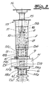
- a fire protection shut-off device for ventilation ducts or air outlets which in its basic structure on the one hand a mounting housing 1 of z. B. plastic with a valve seat 2 arranged therein and on the other hand held under spring action in the open position valve closing body 3, which is transferred at a predetermined temperature by the force of a closing spring 4 in the closed position or fast in the closed position.
- a valve rod 5 Connected to the valve closing body 3 is a valve rod 5 surrounded by the closing spring 4, which is guided in a guide bush 6 connected to the installation housing 1.
- the guide bush 6 is formed as a separate component (made of metal) and fastened in a holder H (made of plastic) of the installation housing 1.
- the valve rod 5 is associated with a locking device 7, which locks the valve rod 5 and the valve rod 5 located in the closed position valve closing body 3.
- This locking device 7 has a connected to the valve rod 5 expanding element 8 in the form of a spreading spring 8, which spreads in the transition from the open position to the closed position, against a locking seat 9 in or on the guide bush.
- the locking seat 9 is formed in the embodiment as arranged in the guide bushing 6, inner peripheral side completely encircling inner collar 9.
- This inner collar 9 forms as it were a completely circumferential locking shoulder or a locking seat in the form of an annular surface 9 of predetermined width.
- the expansion element 8 is designed as a spreading spring 8 made of metal.
- the spreading spring 8 has two substantially parallel to the axis extending spring leg 10 of predetermined length L, which in the transition from the open position to the closed position radially are spread apart.
- the spring legs 10 are connected to an annular mounting collar 11.
- Spring leg 10 and mounting collar 11 are integrally formed.
- the spreading spring 8 in the side view has a substantially U-shaped configuration.
- z. B. three or four spring legs are worked.
- the two spring legs 10 are formed part-cylindrical shell-shaped, that is, that the spring legs are arc-shaped or curved in cross-section.
- the guide bush 6 has on the inside a circumferential collar or an annular surface 12 of predetermined width as an abutment for the closing spring 4.
- a fusible link cap 13 is screwed, which has a lid 14 fastened by means of fusing solder.
- the valve rod 5 at the end has a pressure piece 15, which is pressed in the closed position by the closing spring 4 against the cover 14 of the fusible link cap 13.
- One end of the pressure piece 15 bears against the cover 14, while against the other end the closing spring 4 - with the interposition of the mounting collar 11 of the spreading spring and possibly one or more washers or spacers 16 - presses.
- the valve rod 5 has end threaded portions 5a, 5b, at one end 5a can thereby the valve closing body 3 mount, while at the opposite end 5b, the pressure piece 15 - with the interposition of Sp Schwarzimplantations 8 and a spacer 16 - is attached.
- the fire protection shut-off device according to the invention works as follows.
- Fig. 2 shows first the open position in which the valve closing body 3 is arranged at a predetermined distance from the valve seat 2 and thus allows air to pass through.
- the closing spring is the fourth curious; excited.
- the screwed-on solder plug 13 or its lid 14 holds the spring-loaded valve rod 5 down.
- the ends 10 'of the spring legs 10 of the spreading spring 8 are arranged in this functional position below the annular locking seat 9 and pressed by the inner wall 17b of the guide bush 6 inwardly or held.
- the spreading spring 10 is stretched.
- valve rod 5 is pressed by the closing spring 4 in the closing direction and the valve closing body 3 is pulled into the valve seat 2.
- the valve rod 5 and the spreading spring 8 attached thereto is transferred from the position shown in FIG. 2 in the functional position shown in Fig. 3.
- the spring legs 10 or their ends 10' are automatically and automatically spread apart, so that the ends 10 'rest against the spring leg 10 against the locking seat 9.
- the actuating paths are coordinated so that the locking seat 9 is actually run over during the transition from the open position to the closed position, so that actually takes place a locking or blocking of the valve closing body 3 in the closed position.
- the adjustment of the arrangement takes place so that the locking seat 9 is actually run over by the ends 10 'of the spring legs 10.
- the ends 10 'of the spring legs 10 are then preferably exactly on the locking seat 9 to the plant.
- the blocking works well even if, in the closed position between the ends of the spring legs and the locking seat a certain assembly-related play in the axial direction is present. Opening the shut-off device is then prevented.
- the guide bush 6 is a substantially hollow-cylindrical component with different inner diameter ranges 17a, 17b, 17c distributed over the length and different outer diameter ranges.
- the guide region 17a with an inner diameter D2 for the valve rod 5 with the outer diameter D1 can first be seen.
- the spring receiving region 17b adjoins this guide region 17a with the interposition of the annular abutment 12 for the closing spring 4.
- This spring receiving area 17b has an enlarged diameter D3 relative to the guide area 17a, so that on the one hand it can receive the closing spring 4 and on the other hand in the closed position also the spring legs 10 of the spreading spring 8.
- the locking region 17c Adjoining the end of the guide bush 6 facing the fusible link cap 13, the locking region 17c then adjoins this spring receiving region 17b with a further enlarged diameter D4 relative to the spring receiving region 17b, namely with the interposition of the annular detent seat 9.
- the guide bush 6 is externally provided with two external threads 18a, 18b, on each of which a fastening nut 19a, 19b or a fastening ring can be screwed.
- the guide bush 6 can be fixed to the holder H of the mounting housing 1.
- an adjustment of the arrangement can take place.
- the cap 13 can be screwed onto the external thread 18b facing away from the valve closing body 3, with a corresponding adjustment also being able to take place here.
Landscapes
- Health & Medical Sciences (AREA)
- Public Health (AREA)
- Business, Economics & Management (AREA)
- Emergency Management (AREA)
- Safety Valves (AREA)
- Fire Alarms (AREA)
- Special Wing (AREA)
- Fire-Detection Mechanisms (AREA)
- Building Environments (AREA)
- Control Of Combustion (AREA)
- Specific Sealing Or Ventilating Devices For Doors And Windows (AREA)
- Temperature-Responsive Valves (AREA)
Priority Applications (1)
| Application Number | Priority Date | Filing Date | Title |
|---|---|---|---|
| PL04026345T PL1555044T3 (pl) | 2004-01-15 | 2004-11-05 | Przeciwpożarowe urządzenie odcinające |
Applications Claiming Priority (2)
| Application Number | Priority Date | Filing Date | Title |
|---|---|---|---|
| DE102004002162 | 2004-01-15 | ||
| DE102004002162A DE102004002162B4 (de) | 2004-01-15 | 2004-01-15 | Feuerschutz-Absperrvorrichtung |
Publications (3)
| Publication Number | Publication Date |
|---|---|
| EP1555044A2 EP1555044A2 (de) | 2005-07-20 |
| EP1555044A3 EP1555044A3 (de) | 2006-10-18 |
| EP1555044B1 true EP1555044B1 (de) | 2008-01-16 |
Family
ID=34609569
Family Applications (1)
| Application Number | Title | Priority Date | Filing Date |
|---|---|---|---|
| EP04026345A Expired - Lifetime EP1555044B1 (de) | 2004-01-15 | 2004-11-05 | Feuerschutz-Absperrvorrichtung |
Country Status (5)
| Country | Link |
|---|---|
| EP (1) | EP1555044B1 (pl) |
| AT (1) | ATE383894T1 (pl) |
| DE (2) | DE102004002162B4 (pl) |
| ES (1) | ES2295760T3 (pl) |
| PL (1) | PL1555044T3 (pl) |
Families Citing this family (5)
| Publication number | Priority date | Publication date | Assignee | Title |
|---|---|---|---|---|
| CN109944972B (zh) * | 2019-03-04 | 2025-06-27 | 山东中科恒基建材有限公司 | 防火阀用执行机构 |
| CN109958808B (zh) * | 2019-03-04 | 2025-08-15 | 山东中科恒基建材有限公司 | 防火阀执行机构 |
| CN112344073B (zh) * | 2020-11-09 | 2022-05-10 | 浙江天齐通风设备有限公司 | 一种防火强密性的防火阀 |
| CN113551068B (zh) * | 2021-08-09 | 2025-06-27 | 山东中科恒基建材有限公司 | 带有锁定机构的防火止逆阀和具有其的烟道系统 |
| CN116164406B (zh) * | 2022-12-29 | 2025-11-14 | 珠海格力电器股份有限公司 | 风道结构及送风装置 |
Family Cites Families (5)
| Publication number | Priority date | Publication date | Assignee | Title |
|---|---|---|---|---|
| FR2372360A1 (fr) | 1976-11-18 | 1978-06-23 | Mineur Becourt | Dispositif d'obturation a clapet a grande vitesse de reaction |
| DE7901560U1 (de) * | 1979-01-20 | 1979-06-21 | Schako Metallwarenfabrik Ferdinand Schad Gmbh, 7201 Kolbingen | Tellerventil fuer lueftungsanlagen |
| DE3212715A1 (de) * | 1982-04-05 | 1983-10-06 | Maico Elektroapparate | Brandschutzvorrichtung fuer lueftungskanaele von gebaeuden |
| DE8916043U1 (de) * | 1989-09-11 | 1993-02-04 | Lunos-Lüftung GmbH & Co Ventilatoren KG, 1000 Berlin | Lüftungsgerät |
| DE19911246B4 (de) * | 1999-03-13 | 2004-04-15 | Eidmann, Jürgen | Feuerschutz-Absperrvorrichtung |
-
2004
- 2004-01-15 DE DE102004002162A patent/DE102004002162B4/de not_active Withdrawn - After Issue
- 2004-11-05 EP EP04026345A patent/EP1555044B1/de not_active Expired - Lifetime
- 2004-11-05 ES ES04026345T patent/ES2295760T3/es not_active Expired - Lifetime
- 2004-11-05 AT AT04026345T patent/ATE383894T1/de active
- 2004-11-05 DE DE502004005955T patent/DE502004005955D1/de not_active Expired - Lifetime
- 2004-11-05 PL PL04026345T patent/PL1555044T3/pl unknown
Also Published As
| Publication number | Publication date |
|---|---|
| EP1555044A2 (de) | 2005-07-20 |
| ATE383894T1 (de) | 2008-02-15 |
| DE102004002162A1 (de) | 2005-08-11 |
| DE502004005955D1 (de) | 2008-03-06 |
| PL1555044T3 (pl) | 2008-06-30 |
| DE102004002162B4 (de) | 2007-10-31 |
| EP1555044A3 (de) | 2006-10-18 |
| ES2295760T3 (es) | 2008-04-16 |
Similar Documents
| Publication | Publication Date | Title |
|---|---|---|
| EP3290757B1 (de) | Drehschieber mit kompakter dichtungseinheit | |
| DE4427943A1 (de) | Hydraulisches Spielausgleichselement für die Ventilsteuerung von Brennkraftmaschinen | |
| DE4110583C2 (de) | Korrosionsverhindernde Hülsenvorrichtung sowie Montagewerkzeuge zu ihrer Montage | |
| EP1468220B1 (de) | Armatur | |
| DE102004002162B4 (de) | Feuerschutz-Absperrvorrichtung | |
| EP1048040B1 (de) | Vorrichtung zur nothandbetätigung bei schaltmagneten | |
| DE3103698C2 (de) | Mechanische Reibungsverriegelung | |
| DE4011414A1 (de) | Einrastbare gewindemutter | |
| DE19911246B4 (de) | Feuerschutz-Absperrvorrichtung | |
| DE19651918A1 (de) | Axial einstellbares Abstützelement | |
| EP0883765B1 (de) | Thermische armaturensicherung zum automatischen absperren von leitungen | |
| WO2019166282A1 (de) | Kugelsperrbolzen | |
| DE10343928B3 (de) | Ausstellfeder | |
| DE102004028039B3 (de) | Gassteckdose | |
| EP1046974A2 (de) | Heizkörperventil-Steueraufsatz | |
| DE102009051594B4 (de) | Haken, insbesondere für Sicherheitseinrichtungen | |
| DE2757901C3 (de) | Anschlußvorrichtung für einen Metallschlauch | |
| DE19813307B4 (de) | Absperrorgan mit einem Kugelhahn | |
| DE102019210759A1 (de) | Riegeleinrichtung | |
| DE19837146B4 (de) | Brandschutzeinsatz für gasführende Rohrdurchgänge | |
| DE19813306A1 (de) | Schalter einer Absperranlage für eine Gasleitung | |
| DE19849109B4 (de) | Verbindungselement | |
| DE202011001955U1 (de) | Brandschutzventil und Gaszähler | |
| DE1550420C (de) | Spindelabsperrventil fur Hochdruck sauerstoff | |
| DE29918913U1 (de) | Leuchte |
Legal Events
| Date | Code | Title | Description |
|---|---|---|---|
| PUAI | Public reference made under article 153(3) epc to a published international application that has entered the european phase |
Free format text: ORIGINAL CODE: 0009012 |
|
| AK | Designated contracting states |
Kind code of ref document: A2 Designated state(s): AT BE BG CH CY CZ DE DK EE ES FI FR GB GR HU IE IS IT LI LU MC NL PL PT RO SE SI SK TR |
|
| AX | Request for extension of the european patent |
Extension state: AL HR LT LV MK YU |
|
| PUAL | Search report despatched |
Free format text: ORIGINAL CODE: 0009013 |
|
| AK | Designated contracting states |
Kind code of ref document: A3 Designated state(s): AT BE BG CH CY CZ DE DK EE ES FI FR GB GR HU IE IS IT LI LU MC NL PL PT RO SE SI SK TR |
|
| AX | Request for extension of the european patent |
Extension state: AL HR LT LV MK YU |
|
| 17P | Request for examination filed |
Effective date: 20061115 |
|
| AKX | Designation fees paid |
Designated state(s): AT BE BG CH CY CZ DE DK EE ES FI FR GB GR HU IE IS IT LI LU MC NL PL PT RO SE SI SK TR |
|
| GRAP | Despatch of communication of intention to grant a patent |
Free format text: ORIGINAL CODE: EPIDOSNIGR1 |
|
| GRAS | Grant fee paid |
Free format text: ORIGINAL CODE: EPIDOSNIGR3 |
|
| GRAA | (expected) grant |
Free format text: ORIGINAL CODE: 0009210 |
|
| AK | Designated contracting states |
Kind code of ref document: B1 Designated state(s): AT BE BG CH CY CZ DE DK EE ES FI FR GB GR HU IE IS IT LI LU MC NL PL PT RO SE SI SK TR |
|
| REG | Reference to a national code |
Ref country code: GB Ref legal event code: FG4D Free format text: NOT ENGLISH |
|
| REG | Reference to a national code |
Ref country code: CH Ref legal event code: NV Representative=s name: KELLER & PARTNER PATENTANWAELTE AG Ref country code: CH Ref legal event code: EP |
|
| REG | Reference to a national code |
Ref country code: IE Ref legal event code: FG4D Free format text: LANGUAGE OF EP DOCUMENT: GERMAN |
|
| REF | Corresponds to: |
Ref document number: 502004005955 Country of ref document: DE Date of ref document: 20080306 Kind code of ref document: P |
|
| GBT | Gb: translation of ep patent filed (gb section 77(6)(a)/1977) |
Effective date: 20080312 |
|
| REG | Reference to a national code |
Ref country code: ES Ref legal event code: FG2A Ref document number: 2295760 Country of ref document: ES Kind code of ref document: T3 |
|
| PG25 | Lapsed in a contracting state [announced via postgrant information from national office to epo] |
Ref country code: NL Free format text: LAPSE BECAUSE OF FAILURE TO SUBMIT A TRANSLATION OF THE DESCRIPTION OR TO PAY THE FEE WITHIN THE PRESCRIBED TIME-LIMIT Effective date: 20080116 |
|
| REG | Reference to a national code |
Ref country code: PL Ref legal event code: T3 |
|
| NLV1 | Nl: lapsed or annulled due to failure to fulfill the requirements of art. 29p and 29m of the patents act | ||
| PG25 | Lapsed in a contracting state [announced via postgrant information from national office to epo] |
Ref country code: IS Free format text: LAPSE BECAUSE OF FAILURE TO SUBMIT A TRANSLATION OF THE DESCRIPTION OR TO PAY THE FEE WITHIN THE PRESCRIBED TIME-LIMIT Effective date: 20080516 Ref country code: FI Free format text: LAPSE BECAUSE OF FAILURE TO SUBMIT A TRANSLATION OF THE DESCRIPTION OR TO PAY THE FEE WITHIN THE PRESCRIBED TIME-LIMIT Effective date: 20080116 |
|
| PG25 | Lapsed in a contracting state [announced via postgrant information from national office to epo] |
Ref country code: BG Free format text: LAPSE BECAUSE OF FAILURE TO SUBMIT A TRANSLATION OF THE DESCRIPTION OR TO PAY THE FEE WITHIN THE PRESCRIBED TIME-LIMIT Effective date: 20080416 |
|
| PG25 | Lapsed in a contracting state [announced via postgrant information from national office to epo] |
Ref country code: SI Free format text: LAPSE BECAUSE OF FAILURE TO SUBMIT A TRANSLATION OF THE DESCRIPTION OR TO PAY THE FEE WITHIN THE PRESCRIBED TIME-LIMIT Effective date: 20080116 Ref country code: PT Free format text: LAPSE BECAUSE OF FAILURE TO SUBMIT A TRANSLATION OF THE DESCRIPTION OR TO PAY THE FEE WITHIN THE PRESCRIBED TIME-LIMIT Effective date: 20080616 |
|
| REG | Reference to a national code |
Ref country code: IE Ref legal event code: FD4D |
|
| ET | Fr: translation filed | ||
| PG25 | Lapsed in a contracting state [announced via postgrant information from national office to epo] |
Ref country code: SK Free format text: LAPSE BECAUSE OF FAILURE TO SUBMIT A TRANSLATION OF THE DESCRIPTION OR TO PAY THE FEE WITHIN THE PRESCRIBED TIME-LIMIT Effective date: 20080116 Ref country code: DK Free format text: LAPSE BECAUSE OF FAILURE TO SUBMIT A TRANSLATION OF THE DESCRIPTION OR TO PAY THE FEE WITHIN THE PRESCRIBED TIME-LIMIT Effective date: 20080116 Ref country code: SE Free format text: LAPSE BECAUSE OF FAILURE TO SUBMIT A TRANSLATION OF THE DESCRIPTION OR TO PAY THE FEE WITHIN THE PRESCRIBED TIME-LIMIT Effective date: 20080416 Ref country code: IE Free format text: LAPSE BECAUSE OF FAILURE TO SUBMIT A TRANSLATION OF THE DESCRIPTION OR TO PAY THE FEE WITHIN THE PRESCRIBED TIME-LIMIT Effective date: 20080116 |
|
| PLBE | No opposition filed within time limit |
Free format text: ORIGINAL CODE: 0009261 |
|
| STAA | Information on the status of an ep patent application or granted ep patent |
Free format text: STATUS: NO OPPOSITION FILED WITHIN TIME LIMIT |
|
| PG25 | Lapsed in a contracting state [announced via postgrant information from national office to epo] |
Ref country code: RO Free format text: LAPSE BECAUSE OF FAILURE TO SUBMIT A TRANSLATION OF THE DESCRIPTION OR TO PAY THE FEE WITHIN THE PRESCRIBED TIME-LIMIT Effective date: 20080116 |
|
| 26N | No opposition filed |
Effective date: 20081017 |
|
| PG25 | Lapsed in a contracting state [announced via postgrant information from national office to epo] |
Ref country code: EE Free format text: LAPSE BECAUSE OF FAILURE TO SUBMIT A TRANSLATION OF THE DESCRIPTION OR TO PAY THE FEE WITHIN THE PRESCRIBED TIME-LIMIT Effective date: 20080116 |
|
| PG25 | Lapsed in a contracting state [announced via postgrant information from national office to epo] |
Ref country code: MC Free format text: LAPSE BECAUSE OF NON-PAYMENT OF DUE FEES Effective date: 20081130 |
|
| PG25 | Lapsed in a contracting state [announced via postgrant information from national office to epo] |
Ref country code: CY Free format text: LAPSE BECAUSE OF FAILURE TO SUBMIT A TRANSLATION OF THE DESCRIPTION OR TO PAY THE FEE WITHIN THE PRESCRIBED TIME-LIMIT Effective date: 20080116 |
|
| PG25 | Lapsed in a contracting state [announced via postgrant information from national office to epo] |
Ref country code: HU Free format text: LAPSE BECAUSE OF FAILURE TO SUBMIT A TRANSLATION OF THE DESCRIPTION OR TO PAY THE FEE WITHIN THE PRESCRIBED TIME-LIMIT Effective date: 20080717 Ref country code: LU Free format text: LAPSE BECAUSE OF NON-PAYMENT OF DUE FEES Effective date: 20081105 |
|
| PG25 | Lapsed in a contracting state [announced via postgrant information from national office to epo] |
Ref country code: TR Free format text: LAPSE BECAUSE OF FAILURE TO SUBMIT A TRANSLATION OF THE DESCRIPTION OR TO PAY THE FEE WITHIN THE PRESCRIBED TIME-LIMIT Effective date: 20080116 |
|
| PG25 | Lapsed in a contracting state [announced via postgrant information from national office to epo] |
Ref country code: GR Free format text: LAPSE BECAUSE OF FAILURE TO SUBMIT A TRANSLATION OF THE DESCRIPTION OR TO PAY THE FEE WITHIN THE PRESCRIBED TIME-LIMIT Effective date: 20080417 |
|
| REG | Reference to a national code |
Ref country code: CH Ref legal event code: PCAR Free format text: NEW ADDRESS: EIGERSTRASSE 2 POSTFACH, 3000 BERN 14 (CH) |
|
| REG | Reference to a national code |
Ref country code: FR Ref legal event code: PLFP Year of fee payment: 12 |
|
| REG | Reference to a national code |
Ref country code: FR Ref legal event code: PLFP Year of fee payment: 13 |
|
| PGFP | Annual fee paid to national office [announced via postgrant information from national office to epo] |
Ref country code: CH Payment date: 20161121 Year of fee payment: 13 Ref country code: CZ Payment date: 20161104 Year of fee payment: 13 |
|
| PGFP | Annual fee paid to national office [announced via postgrant information from national office to epo] |
Ref country code: ES Payment date: 20161114 Year of fee payment: 13 Ref country code: PL Payment date: 20161024 Year of fee payment: 13 Ref country code: BE Payment date: 20161118 Year of fee payment: 13 Ref country code: IT Payment date: 20161123 Year of fee payment: 13 Ref country code: AT Payment date: 20161121 Year of fee payment: 13 |
|
| REG | Reference to a national code |
Ref country code: FR Ref legal event code: PLFP Year of fee payment: 14 |
|
| REG | Reference to a national code |
Ref country code: AT Ref legal event code: MM01 Ref document number: 383894 Country of ref document: AT Kind code of ref document: T Effective date: 20171105 |
|
| PG25 | Lapsed in a contracting state [announced via postgrant information from national office to epo] |
Ref country code: CH Free format text: LAPSE BECAUSE OF NON-PAYMENT OF DUE FEES Effective date: 20171130 Ref country code: CZ Free format text: LAPSE BECAUSE OF NON-PAYMENT OF DUE FEES Effective date: 20171105 Ref country code: LI Free format text: LAPSE BECAUSE OF NON-PAYMENT OF DUE FEES Effective date: 20171130 |
|
| PG25 | Lapsed in a contracting state [announced via postgrant information from national office to epo] |
Ref country code: AT Free format text: LAPSE BECAUSE OF NON-PAYMENT OF DUE FEES Effective date: 20171105 |
|
| REG | Reference to a national code |
Ref country code: BE Ref legal event code: MM Effective date: 20171130 |
|
| PG25 | Lapsed in a contracting state [announced via postgrant information from national office to epo] |
Ref country code: IT Free format text: LAPSE BECAUSE OF NON-PAYMENT OF DUE FEES Effective date: 20171105 |
|
| PG25 | Lapsed in a contracting state [announced via postgrant information from national office to epo] |
Ref country code: BE Free format text: LAPSE BECAUSE OF NON-PAYMENT OF DUE FEES Effective date: 20171130 |
|
| REG | Reference to a national code |
Ref country code: ES Ref legal event code: FD2A Effective date: 20181226 |
|
| PG25 | Lapsed in a contracting state [announced via postgrant information from national office to epo] |
Ref country code: ES Free format text: LAPSE BECAUSE OF NON-PAYMENT OF DUE FEES Effective date: 20171106 |
|
| PGFP | Annual fee paid to national office [announced via postgrant information from national office to epo] |
Ref country code: GB Payment date: 20181120 Year of fee payment: 15 Ref country code: FR Payment date: 20181123 Year of fee payment: 15 |
|
| PG25 | Lapsed in a contracting state [announced via postgrant information from national office to epo] |
Ref country code: PL Free format text: LAPSE BECAUSE OF NON-PAYMENT OF DUE FEES Effective date: 20171105 |
|
| REG | Reference to a national code |
Ref country code: DE Ref legal event code: R082 Ref document number: 502004005955 Country of ref document: DE Representative=s name: ANDREJEWSKI HONKE PATENT- UND RECHTSANWAELTE P, DE Ref country code: DE Ref legal event code: R081 Ref document number: 502004005955 Country of ref document: DE Owner name: STRULIK GMBH, DE Free format text: FORMER OWNER: EIDMANN, JUERGEN, 61348 BAD HOMBURG, DE |
|
| PGFP | Annual fee paid to national office [announced via postgrant information from national office to epo] |
Ref country code: DE Payment date: 20191119 Year of fee payment: 16 |
|
| GBPC | Gb: european patent ceased through non-payment of renewal fee |
Effective date: 20191105 |
|
| PG25 | Lapsed in a contracting state [announced via postgrant information from national office to epo] |
Ref country code: FR Free format text: LAPSE BECAUSE OF NON-PAYMENT OF DUE FEES Effective date: 20191130 Ref country code: GB Free format text: LAPSE BECAUSE OF NON-PAYMENT OF DUE FEES Effective date: 20191105 |
|
| REG | Reference to a national code |
Ref country code: DE Ref legal event code: R119 Ref document number: 502004005955 Country of ref document: DE |
|
| PG25 | Lapsed in a contracting state [announced via postgrant information from national office to epo] |
Ref country code: DE Free format text: LAPSE BECAUSE OF NON-PAYMENT OF DUE FEES Effective date: 20210601 |