EP1553547A2 - Signalanzeigevorrichtung - Google Patents
Signalanzeigevorrichtung Download PDFInfo
- Publication number
- EP1553547A2 EP1553547A2 EP04030269A EP04030269A EP1553547A2 EP 1553547 A2 EP1553547 A2 EP 1553547A2 EP 04030269 A EP04030269 A EP 04030269A EP 04030269 A EP04030269 A EP 04030269A EP 1553547 A2 EP1553547 A2 EP 1553547A2
- Authority
- EP
- European Patent Office
- Prior art keywords
- data
- axis
- mathematical
- waveform
- channel
- Prior art date
- Legal status (The legal status is an assumption and is not a legal conclusion. Google has not performed a legal analysis and makes no representation as to the accuracy of the status listed.)
- Withdrawn
Links
- 230000014509 gene expression Effects 0.000 claims abstract description 41
- 230000006870 function Effects 0.000 claims description 14
- 238000005070 sampling Methods 0.000 claims description 12
- 238000003672 processing method Methods 0.000 abstract description 3
- 238000004458 analytical method Methods 0.000 abstract description 2
- 230000001360 synchronised effect Effects 0.000 description 4
- 238000010586 diagram Methods 0.000 description 3
- 230000004044 response Effects 0.000 description 2
- 238000004364 calculation method Methods 0.000 description 1
- 238000010195 expression analysis Methods 0.000 description 1
- 230000000977 initiatory effect Effects 0.000 description 1
- 239000004973 liquid crystal related substance Substances 0.000 description 1
- 238000003754 machining Methods 0.000 description 1
- 238000000034 method Methods 0.000 description 1
Images


Classifications
-
- G—PHYSICS
- G01—MEASURING; TESTING
- G01R—MEASURING ELECTRIC VARIABLES; MEASURING MAGNETIC VARIABLES
- G01R13/00—Arrangements for displaying electric variables or waveforms
- G01R13/02—Arrangements for displaying electric variables or waveforms for displaying measured electric variables in digital form
-
- G—PHYSICS
- G09—EDUCATION; CRYPTOGRAPHY; DISPLAY; ADVERTISING; SEALS
- G09G—ARRANGEMENTS OR CIRCUITS FOR CONTROL OF INDICATING DEVICES USING STATIC MEANS TO PRESENT VARIABLE INFORMATION
- G09G1/00—Control arrangements or circuits, of interest only in connection with cathode-ray tube indicators; General aspects or details, e.g. selection emphasis on particular characters, dashed line or dotted line generation; Preprocessing of data
- G09G1/06—Control arrangements or circuits, of interest only in connection with cathode-ray tube indicators; General aspects or details, e.g. selection emphasis on particular characters, dashed line or dotted line generation; Preprocessing of data using single beam tubes, e.g. three-dimensional or perspective representation, rotation or translation of display pattern, hidden lines, shadows
- G09G1/14—Control arrangements or circuits, of interest only in connection with cathode-ray tube indicators; General aspects or details, e.g. selection emphasis on particular characters, dashed line or dotted line generation; Preprocessing of data using single beam tubes, e.g. three-dimensional or perspective representation, rotation or translation of display pattern, hidden lines, shadows the beam tracing a pattern independent of the information to be displayed, this latter determining the parts of the pattern rendered respectively visible and invisible
- G09G1/16—Control arrangements or circuits, of interest only in connection with cathode-ray tube indicators; General aspects or details, e.g. selection emphasis on particular characters, dashed line or dotted line generation; Preprocessing of data using single beam tubes, e.g. three-dimensional or perspective representation, rotation or translation of display pattern, hidden lines, shadows the beam tracing a pattern independent of the information to be displayed, this latter determining the parts of the pattern rendered respectively visible and invisible the pattern of rectangular co-ordinates extending over the whole area of the screen, i.e. television type raster
- G09G1/162—Control arrangements or circuits, of interest only in connection with cathode-ray tube indicators; General aspects or details, e.g. selection emphasis on particular characters, dashed line or dotted line generation; Preprocessing of data using single beam tubes, e.g. three-dimensional or perspective representation, rotation or translation of display pattern, hidden lines, shadows the beam tracing a pattern independent of the information to be displayed, this latter determining the parts of the pattern rendered respectively visible and invisible the pattern of rectangular co-ordinates extending over the whole area of the screen, i.e. television type raster for displaying digital inputs as analog magnitudes, e.g. curves, bar graphs, coordinate axes, singly or in combination with alpha-numeric characters
Definitions
- the present invention relates to a waveform display apparatus which collects digital data from a plurality of channels, and displays information relating to the collected digital data of each channel in the form of a time-series waveform or performs a mathematical operation using the data between the plurality of channels and displays information relating to the collected digital data in the form of a waveform by using the result of the mathematical operation.
- control apparatuses including numerical control apparatuses
- Various kinds of control apparatuses are often constructed so as to be able to monitor and observe the condition of a control target by displaying the condition based on the various kinds of data detected from the control target.
- data such as shown below are stored in its internal array.
- Time data (n) t ⁇ n
- First channel data (n) CH1(n)
- Second channel data (n) CH2(n) where t is sampling time, and n is data index.
- X(n) Time data (n)
- Y1(n) First channel data (n)
- Y2(n) Second channel data (n)
- a waveform is displayed by plotting the combination of X and Y1 data or X and Y2 data on an XY graph.
- first channel data and the second channel data are data both having positional dimensions
- Y(n) Second channel data (n)
- the locus of two-dimensional positions can be displayed by using the combination of X and Y data and plotting them on an XY graph.
- a waveform display apparatus that solves the above problem performs a mathematical operation on signals output from a plurality of channels, and displays information relating to the signals in the form of a waveform based on data obtained from the mathematical operation
- the apparatus comprises: sampling data storing means for sampling the signals output from the plurality of channels, and for storing the sampled signals as digital data; mathematical expression entering means for entering at least one mathematical expression; mathematical operation means for reading out the digital data of at least one of the plurality of channels from the sampling data storing means, and for applying the at least one mathematical expression to the readout digital data; and a display unit for displaying the information relating to the signals in the form of a waveform based on data representing a mathematical operation result obtained by applying in the mathematical operation means the at least one mathematical expression to the digital data of the at least one channel.
- the waveform is displayed by taking a first axis as a time axis or a position axis and a second axis as an axis representing the information relating to the signals based on the mathematical operation result.
- the waveform representing the information relating to the signals is displayed by plotting, along a first axis, data representing a first mathematical operation result obtained by applying one or more of mathematical expressions selected from among the at least one mathematical operation to the digital data of the at least one channel, while plotting along a second axis, data representing a second mathematical operation result obtained by applying the other one or more of mathematical expressions selected from among the at least one mathematical operation to the digital data of the at least one channel.
- the mathematical expression consists of one operation or a combination of at least two operations selected from among addition, subtraction, multiplication, division, trigonometric functions, raising to a power, square rooting, exponential functions, and logarithmic functions.
- the display unit is a display unit for a numerical control apparatus that controls a machine tool.
- the display unit is a display unit for a personal computer.
- the waveform display apparatus of the present invention as the information relating to the data acquired from the plurality of channels can be displayed in the form of a waveform on the display unit based on the result of the mathematical operation performed on the acquired data by using a user-entered mathematical equation, the freedom in selecting mathematical expressions increases.
- Figure 1 is a block diagram showing the essential portions of a numerical control apparatus according to one embodiment to which the waveform display apparatus of the present invention is applied.
- Figure 2 is a diagram showing how work is machined in a two-dimensional shape by operating a rotating axis and a linear axis in synchronized fashion.
- Figure 3 is a flowchart illustrating the waveform display processing performed by a CPU in the numerical control apparatus of the embodiment.
- Figure 4 is a graph showing waveforms obtained from data sampled by taking the X axis as a time axis and the Y axis as an axis representing the position of the linear axis of a cutter and the angle position of the rotating axis of the work.
- Figure 5 is a graph showing waveforms obtained from mathematical operation result data by taking the X axis as a time axis and the Y axis as an axis representing (Position of the linear axis of the cutter) ⁇ cos(Angle of the rotating axis) and (Position of the linear axis of the cutter) ⁇ sin(Angle of the rotating axis).
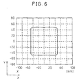
- Figure 6 is a graph showing waveforms obtained from mathematical operation result data by taking the X axis as an axis representing (Position of the linear axis of the cutter) ⁇ cos(Angle of the rotating axis) and the Y axis as an axis representing (Position of the linear axis of the cutter ⁇ sin (Angle of the rotating axis).
- FIG. 1 is a block diagram showing the essential portions of a numerical control apparatus according to one embodiment to which the waveform display apparatus of the present invention is applied.
- a CPU 11 is a processor which controls the entire operation of the numerical control apparatus 10. The CPU 11 reads a system program out of a ROM 12 via a bus 19, and controls the entire operation of the numerical control apparatus 10 in accordance with the system program.
- a RAM 13 temporarily stores calculation data, display data, and various kinds of data.
- the various kinds of data refer to the data that the operator entered via a display unit/manual input unit 20 which comprises a display unit, such as a CRT or liquid crystal display, and a manual input means, such as a keyboard.
- the display unit/manual input unit 20 also functions as a mathematical expression entering means according to the present invention, and the user enters a desired mathematical expression (at least one mathematical expression) from the display unit/manual input unit 20.
- a CMOS memory 14 is powered by a battery not shown, and is thus constructed as a nonvolatile memory which preserves its stored contents when power is turned off to the numerical control apparatus 10.
- Programs such as a machining program loaded via an interface 15, a machining program entered via the display unit/manual input unit 20, etc. are stored in the CMOS memory 14. Further, in the present embodiment, at least one mathematical expression entered via the display unit/manual input unit 20 is stored in the CMOS memory 14.
- the ROM 12 permanently stores various system programs for implementing edit functions necessary to create and edit machining programs, and for performing the waveform display processing necessary to display a waveform in a waveform display area on the display screen of the display unit/manual input unit 20 which, as will be described later, displays information relating to the data of at least one channel based on the data representing the mathematical operation result obtained by applying the at least one mathematical expression to the digital data of the at least one channel.
- the interface 15 enables the numerical control apparatus 10 to connect to external devices.
- a PMC (Programmable Machine Controller) 16 is a sequence program built into the numerical control apparatus 10, and performs control by transferring signals via an I/O unit 17 to and from an auxiliary device (for example, an actuator such as a tool changing robot hand) of a machine tool to be controlled. Further, the I/O unit 17 receives signals from various switches mounted on the operation panel incorporated in the main body of the machine tool being controlled by the numerical control apparatus, and passes the signals to the CPU 11 after applying necessary signal processing.
- Axis control circuits 30 to 32 in response to axis moving amounts commanded by the CPU 11, control the respective axes of the machine (control target) by driving servo motors 50 to 52 for the respective axes via servo amplifiers 40 to 42.
- the servo motors 50 to 52 for the respective axes are each equipped with a built-in position/speed detector, and position/speed feedback control is performed by supplying the position/speed feedback signals from the position/speed detectors to the respective axis control circuits 30 to 32.
- the position/speed feedback configuration is not shown.
- Each of the axis control circuits 30 to 32 is provided with a present position register for storing the present position of a corresponding one of the servo motors 50 to 52 based on the position feedback signal, as in the prior art, but the present position register is not shown in Figure 1.
- the servo motor 50 which drives a rotating feed axis is connected to a first channel (on which the axis control circuit 30 and the servo amplifier 40 are connected), the servo motor 51 which drives a first linear feed axis (X axis) is connected to a second channel (on which the axis control circuit 31 and the servo amplifier 41 are connected), and the servo motor 52 which drives a second linear feed axis (Y axis) is connected to a third channel (on which the axis control circuit 32 and the servo amplifier 42 are connected).
- a spindle control circuit 60 receives a spindle rotation command, and outputs a spindle speed signal to a spindle amplifier 61.
- the spindle amplifier 61 in response to the spindle speed signal, causes a spindle motor 62 to rotate at the commanded rotational speed.
- a position coder 63 is used to control the speed of the spindle motor 62 by supplying feedback pulses to the spindle control circuit 60 in synchronism with the rotation of the spindle motor 62.
- the user enters from the display unit/manual input unit 20 a mathematical expression by specifying a data train X(n) corresponding to the X axis (horizontal axis) and a data train Y(n) corresponding to the Y axis (vertical axis) in the waveform display area on the display screen of the display unit/manual input unit 20.
- the mathematical expression can be entered by selecting one operation or a combination of at least two operations from among addition, subtraction, multiplication, division, trigonometric functions, raising to a power, square rooting, exponential functions, and logarithmic functions.
- the rotating axis (first channel) of the machine tool controlled by the numerical control apparatus 10 is driven by the servo motor 50 to rotate the work
- the first linear feed axis (second channel) is driven by the servo motor 51 to move the cutter in a straight line, cutting a two-dimensional shape by operating the rotating axis and the linear axis in synchronized fashion.
- the angle data of the rotating axis rotating with the work clamped thereon is taken as the position data of the first channel (the value of the present position register that stores the present position of the servo motor 50), and the position data of the linear axis in the linear motion direction of the cutter cutting the work (the value of the present position register that stores the present position of the servo motor 51) is taken as the position data of the second channel; then, these digital data are sampled and stored as digital data.
- figure 3 is a flowchart illustrating the waveform display processing performed by the CPU 11 in the numerical control apparatus 10.
- the CPU 11 performs the processing of Figure 3 at each prescribed sampling interval.
- data of each channel is acquired (step S01). That is, the value of the present position register for each axis (servo motor 50, 51, 52) is read out and stored in association with data index n (whose initial value is "1").
- the CPU 11 analyzes the at least one mathematical expression entered and stored in the CMOS memory 14 (step S02).
- the CPU 11 computes X-axis data and Y-axis data for displaying a graph in accordance with the mathematical expression (step S03). Then, by plotting the combination of the thus computed X-axis data and Y-axis data on an XY graph, information relating to the data acquired from each channel is displayed in the form of a waveform on the display screen of the display unit/manual input unit 20 (step S04). One cycle of the waveform display processing is thus completed.
- provisions may be made to automatically start the waveform display processing upon initiation of cutting work.
- an execution flag is set, for example, when the cutting work is initiated, and reset when the cutting work is completed; when the execution flag is set, the above process from steps S01 to S04 is performed at each sampling interval.
- the result of sampling the angle data of the rotating axis as the first channel describes a substantially linear waveform as shown by a dashed line in Figure 4.
- the values at the left in Figure 4 indicate the angle position (deg) of the rotating axis
- the values at the right in Figure 4 represent the position of the linear axis. From the display screen such as shown in Figure 4, it can be seen that the linear axis is moving in reciprocating fashion, while the rotating axis is rotating constantly in one direction.
- the results of the mathematical operations are displayed on the screen of the display unit as described above, the information relating to the data acquired from each channel, for example, the waveform representing the two-dimensional shape, can be displayed in graph form by reflecting the result obtained by applying the desired mathematical expression that the operator entered.
- the waveform display is produced on the display screen of the display unit/manual input unit 20 of the numerical control apparatus 10, but alternatively, a personal computer may be connected to the numerical control apparatus 10, and the waveform display may be produced on the display screen of the personal computer.
- the above embodiment has been described by taking an example in which the machine tool has three feed axes (three channels) and data of two of the three axes are used, but it will be appreciated that according to the invention, when there are many channels to be controlled, the user can have the desired data displayed in graph form in the desired manner by entering desired mathematical expressions, selecting desired channels, performing mathematical operations using the data of the selected channels, and having the results displayed in graph form.
Landscapes
- Physics & Mathematics (AREA)
- General Physics & Mathematics (AREA)
- Numerical Control (AREA)
- Machine Tool Sensing Apparatuses (AREA)
Applications Claiming Priority (2)
| Application Number | Priority Date | Filing Date | Title |
|---|---|---|---|
| JP2003434747 | 2003-12-26 | ||
| JP2003434747A JP2005189215A (ja) | 2003-12-26 | 2003-12-26 | 波形表示装置 |
Publications (1)
| Publication Number | Publication Date |
|---|---|
| EP1553547A2 true EP1553547A2 (de) | 2005-07-13 |
Family
ID=34587658
Family Applications (1)
| Application Number | Title | Priority Date | Filing Date |
|---|---|---|---|
| EP04030269A Withdrawn EP1553547A2 (de) | 2003-12-26 | 2004-12-21 | Signalanzeigevorrichtung |
Country Status (4)
| Country | Link |
|---|---|
| US (1) | US20050144205A1 (de) |
| EP (1) | EP1553547A2 (de) |
| JP (1) | JP2005189215A (de) |
| CN (1) | CN100357061C (de) |
Cited By (1)
| Publication number | Priority date | Publication date | Assignee | Title |
|---|---|---|---|---|
| EP1923757A3 (de) * | 2006-11-17 | 2009-10-14 | Fanuc Ltd | Vorrichtung zur Darstellung der Bahnkurve eines Tandembetriebs |
Families Citing this family (8)
| Publication number | Priority date | Publication date | Assignee | Title |
|---|---|---|---|---|
| CN101334985B (zh) | 2007-06-27 | 2012-02-01 | 深圳迈瑞生物医疗电子股份有限公司 | 一种波形数据的显示装置及方法 |
| CN102539864B (zh) * | 2010-12-31 | 2016-01-20 | 北京普源精电科技有限公司 | 数字示波器及信号测量方法 |
| US9026945B2 (en) * | 2011-04-28 | 2015-05-05 | Tektronix, Inc. | Method of grouping waveforms for a single channel on a single display |
| US9496993B1 (en) * | 2012-01-13 | 2016-11-15 | Teledyne Lecroy, Inc. | Noise analysis to reveal jitter and crosstalk's effect on signal integrity |
| US8868486B2 (en) | 2013-03-15 | 2014-10-21 | Palantir Technologies Inc. | Time-sensitive cube |
| JP6687664B2 (ja) * | 2018-04-16 | 2020-04-28 | ファナック株式会社 | 波形表示装置 |
| JP7294927B2 (ja) * | 2019-07-23 | 2023-06-20 | ファナック株式会社 | 相違点抽出装置 |
| DE112021003949T5 (de) * | 2020-09-07 | 2023-05-25 | Fanuc Corporation | Wellenformanzeigevorrichtung |
Family Cites Families (11)
| Publication number | Priority date | Publication date | Assignee | Title |
|---|---|---|---|---|
| US3348234A (en) * | 1962-03-20 | 1967-10-17 | Reliance Electric & Eng Co | Production line operation monitor and recorder |
| US4099240A (en) * | 1977-01-14 | 1978-07-04 | Hewlett-Packard Company | Method and apparatus for programmable and remote numeric control and calibration of electronic instrumentation |
| US4755753A (en) * | 1986-07-23 | 1988-07-05 | General Electric Company | Eddy current surface mapping system for flaw detection |
| US4809189A (en) * | 1986-10-09 | 1989-02-28 | Tektronix, Inc. | Equivalent time waveform data display |
| US5283596A (en) * | 1991-02-05 | 1994-02-01 | Hewlett-Packard Company | Digitally synthesized gray scale for raster scan oscilloscope color display of overlapping multichannel waveforms |
| JP2000210800A (ja) * | 1999-01-27 | 2000-08-02 | Komatsu Ltd | 産業機械のモニタ方法およびその装置 |
| US6466836B1 (en) * | 1999-04-28 | 2002-10-15 | Toshiba America Information Systems, Inc. | Method and apparatus for encoding or decoding a human readable representation of options differentiating products or services |
| CN1338678A (zh) * | 2000-08-16 | 2002-03-06 | 金宝电子工业股份有限公司 | 自动追加进制符号的计算装置及其方法 |
| JP2002283188A (ja) * | 2001-03-23 | 2002-10-03 | Seiko Epson Corp | 加工装置及び加工結果の検出方法 |
| US6952655B2 (en) * | 2001-12-11 | 2005-10-04 | Lecroy Corporation | User defined processing function |
| JP3702845B2 (ja) * | 2001-12-20 | 2005-10-05 | 横河電機株式会社 | 波形表示装置 |
-
2003
- 2003-12-26 JP JP2003434747A patent/JP2005189215A/ja active Pending
-
2004
- 2004-12-21 EP EP04030269A patent/EP1553547A2/de not_active Withdrawn
- 2004-12-22 US US11/017,651 patent/US20050144205A1/en not_active Abandoned
- 2004-12-24 CN CNB2004100970875A patent/CN100357061C/zh not_active Expired - Fee Related
Cited By (1)
| Publication number | Priority date | Publication date | Assignee | Title |
|---|---|---|---|---|
| EP1923757A3 (de) * | 2006-11-17 | 2009-10-14 | Fanuc Ltd | Vorrichtung zur Darstellung der Bahnkurve eines Tandembetriebs |
Also Published As
| Publication number | Publication date |
|---|---|
| JP2005189215A (ja) | 2005-07-14 |
| US20050144205A1 (en) | 2005-06-30 |
| CN1636673A (zh) | 2005-07-13 |
| CN100357061C (zh) | 2007-12-26 |
Similar Documents
| Publication | Publication Date | Title |
|---|---|---|
| US8190287B2 (en) | Tool vector display apparatus for a machine tool with rotational axes | |
| CA2784720C (en) | Predictive control and visualizing system for a nc machine tool | |
| US8483865B2 (en) | Numerical controller with tool trajectory display function | |
| JP4847428B2 (ja) | 加工シミュレーション装置およびそのプログラム | |
| US5400260A (en) | Method of creating machining conditions for NC machine tools | |
| CN109129413B (zh) | 显示速度的机器人系统 | |
| EP1553547A2 (de) | Signalanzeigevorrichtung | |
| US12259703B2 (en) | Control device | |
| JP2762788B2 (ja) | 移動体の動作表示装置及びその表示方法 | |
| EP0428950A2 (de) | Steuergerät um einen Motor in Betrieb zu setzen | |
| JPH03196310A (ja) | 数値制御装置の表示方式 | |
| JPH02257309A (ja) | Ncプログラムの描画方法 | |
| JPH06202724A (ja) | 数値制御装置 | |
| US12422823B2 (en) | Workpiece machining device | |
| EP0419672A1 (de) | Verfahren zum zeichnen des profils eines werkzeugs | |
| JPS59200306A (ja) | Nc機器の移動を図形処理する方法 | |
| CN112904802A (zh) | 程序解析装置 | |
| JPH0885044A (ja) | 加工負荷監視方式 | |
| JPH0592349A (ja) | 数値制御装置 | |
| JPH04252307A (ja) | 対話形数値制御装置 | |
| JPH02257308A (ja) | 加工プログラムのチェック描画方法 | |
| CN116848477A (zh) | 机床、机床的控制方法以及机床的控制程序 | |
| WO1990015374A1 (fr) | Unite de commande numerique | |
| JPH07104712B2 (ja) | ロボットアームの手動制御方法 | |
| JPH0926810A (ja) | 数値制御装置 |
Legal Events
| Date | Code | Title | Description |
|---|---|---|---|
| PUAI | Public reference made under article 153(3) epc to a published international application that has entered the european phase |
Free format text: ORIGINAL CODE: 0009012 |
|
| AK | Designated contracting states |
Kind code of ref document: A2 Designated state(s): AT BE BG CH CY CZ DE DK EE ES FI FR GB GR HU IE IS IT LI LT LU MC NL PL PT RO SE SI SK TR |
|
| AX | Request for extension of the european patent |
Extension state: AL BA HR LV MK YU |
|
| STAA | Information on the status of an ep patent application or granted ep patent |
Free format text: STATUS: THE APPLICATION HAS BEEN WITHDRAWN |
|
| 18W | Application withdrawn |
Effective date: 20080226 |