EP1553004B1 - Stossabsorbierende Lenkung - Google Patents
Stossabsorbierende Lenkung Download PDFInfo
- Publication number
- EP1553004B1 EP1553004B1 EP05004757A EP05004757A EP1553004B1 EP 1553004 B1 EP1553004 B1 EP 1553004B1 EP 05004757 A EP05004757 A EP 05004757A EP 05004757 A EP05004757 A EP 05004757A EP 1553004 B1 EP1553004 B1 EP 1553004B1
- Authority
- EP
- European Patent Office
- Prior art keywords
- steering column
- energy
- impact absorbing
- energy absorbing
- absorbing
- Prior art date
- Legal status (The legal status is an assumption and is not a legal conclusion. Google has not performed a legal analysis and makes no representation as to the accuracy of the status listed.)
- Expired - Lifetime
Links
- 238000010521 absorption reaction Methods 0.000 claims description 15
- 239000002184 metal Substances 0.000 claims description 5
- 229910052751 metal Inorganic materials 0.000 claims description 5
- 229910000831 Steel Inorganic materials 0.000 description 17
- 239000010959 steel Substances 0.000 description 17
- 230000007246 mechanism Effects 0.000 description 15
- XEEYBQQBJWHFJM-UHFFFAOYSA-N Iron Chemical group [Fe] XEEYBQQBJWHFJM-UHFFFAOYSA-N 0.000 description 13
- 230000007423 decrease Effects 0.000 description 3
- 230000003247 decreasing effect Effects 0.000 description 3
- 238000003466 welding Methods 0.000 description 3
- 230000008878 coupling Effects 0.000 description 2
- 238000010168 coupling process Methods 0.000 description 2
- 238000005859 coupling reaction Methods 0.000 description 2
- 238000000465 moulding Methods 0.000 description 2
- 230000000149 penetrating effect Effects 0.000 description 2
- 230000002093 peripheral effect Effects 0.000 description 2
- 230000003190 augmentative effect Effects 0.000 description 1
- 238000005452 bending Methods 0.000 description 1
- 210000000481 breast Anatomy 0.000 description 1
- 238000005266 casting Methods 0.000 description 1
- 230000008859 change Effects 0.000 description 1
- 230000006835 compression Effects 0.000 description 1
- 238000007906 compression Methods 0.000 description 1
- 238000001514 detection method Methods 0.000 description 1
- 230000005611 electricity Effects 0.000 description 1
- 238000005516 engineering process Methods 0.000 description 1
- 229910052742 iron Inorganic materials 0.000 description 1
- 239000000463 material Substances 0.000 description 1
- 238000000034 method Methods 0.000 description 1
- 230000008569 process Effects 0.000 description 1
- 230000009467 reduction Effects 0.000 description 1
- 230000000717 retained effect Effects 0.000 description 1
- 238000000638 solvent extraction Methods 0.000 description 1
- 230000001960 triggered effect Effects 0.000 description 1
Images







Classifications
-
- B—PERFORMING OPERATIONS; TRANSPORTING
- B62—LAND VEHICLES FOR TRAVELLING OTHERWISE THAN ON RAILS
- B62D—MOTOR VEHICLES; TRAILERS
- B62D1/00—Steering controls, i.e. means for initiating a change of direction of the vehicle
- B62D1/02—Steering controls, i.e. means for initiating a change of direction of the vehicle vehicle-mounted
- B62D1/16—Steering columns
- B62D1/18—Steering columns yieldable or adjustable, e.g. tiltable
- B62D1/19—Steering columns yieldable or adjustable, e.g. tiltable incorporating energy-absorbing arrangements, e.g. by being yieldable or collapsible
- B62D1/192—Yieldable or collapsible columns
-
- B—PERFORMING OPERATIONS; TRANSPORTING
- B62—LAND VEHICLES FOR TRAVELLING OTHERWISE THAN ON RAILS
- B62D—MOTOR VEHICLES; TRAILERS
- B62D1/00—Steering controls, i.e. means for initiating a change of direction of the vehicle
- B62D1/02—Steering controls, i.e. means for initiating a change of direction of the vehicle vehicle-mounted
- B62D1/16—Steering columns
- B62D1/18—Steering columns yieldable or adjustable, e.g. tiltable
- B62D1/19—Steering columns yieldable or adjustable, e.g. tiltable incorporating energy-absorbing arrangements, e.g. by being yieldable or collapsible
- B62D1/195—Yieldable supports for the steering column
Definitions
- the present invention relates generally to an impact absorbing type steering column apparatus, and more particularly to a technology which seeks to make a collapse load variable.
- the automobiles manufactured over the recent years broadly take an impact absorbing type steering shaft and an impact absorbing type steering column apparatus for the purpose of preventing the driver from being injured in that case.
- the impact absorbing type steering column apparatus is structured such that the steering column gets separated with the steering shaft when the driver suffers the secondary collision, and normally gets collapsed simultaneously with the steering shaft, and a collision energy is absorbed on that occasion.
- a drawing type collision energy absorbing mechanism takes such a configuration that one side end of an energy absorbing member composed of, e.g., a band-like steel plate is fixed to a car body sided bracket, and a drawing member such as a steel rod etc fitted in a buckling portion formed in the energy absorbing member is provided on the side of the steering column and causes a drawing deformation of the energy absorbing member when the steering column shifts forward.
- an energy absorbing member composed of, e.g., a band-like steel plate is fixed to a car body sided bracket
- a drawing member such as a steel rod etc fitted in a buckling portion formed in the energy absorbing member is provided on the side of the steering column and causes a drawing deformation of the energy absorbing member when the steering column shifts forward.
- the tear-up type collision energy absorbing mechanism takes such a configuration that a central portion of the energy absorbing member composed of, e.g., a band-like steel plate is fixed to the car body sided bracket, two side portions of the energy absorbing member are fixed to the steering column in a way that bends it in a U-shape, and the energy absorbing member is torn up while being deformed by bending when the steering column shifts forward.
- the steering column becomes collapsed when a predetermined collapse load acts, however, this collapse load is normally set based on a kinetic energy generated when a driver having a standard weight secondarily collides with the steering wheel. If the driver is a small-sized women and when a car speed is low, however, as a matter of course, the kinetic energy thereof decreases, and the energy absorption quantity can not be adjusted corresponding to a driver's physique, a car speed etc.
- DE 195 42 491 discloses a steering column having a component which slides axially on the column and which is coupled to first and second energy-absorbing distorting components.
- the sliding component works with a safety belt, having an energy-absorbing coiling mechanism which locks in the eventy of a vehicle collision.
- the coupling at one side of the second component is released when the driver buckles the saftey belt.
- the coupling release device may be on the belt buckle. Alternatively there can be a switch actuated by the buckle and controlling a motor or solenoid.
- One of the embodiments of DE 195 42 491 discloses a steering column comprising collision absorbing means for absorbing a secondary collision of a vehicle, and energy absorption quantity adjusting means for changing an absorption quantity with which said collision energy absorbing means absorbs the secondary collision energy, wherein a magnet can vary the position of a plunger in order to adjust the energy absorption quantity.
- an impact absorbing type steering column apparatus according to claim 1.
- the plunger magnetically attracted by the first coil is moved to a first position and adsorptively held by a first permanent magnet.
- the plunger magnetically attracted by the second coil is moved to a second position from the first position and adsorptively held by a second permanent magnet.
- the operation load is increased by augmenting the plastic deformation quantity of the energy absorbing member.
- the operation load is decreased by reducing the plastic deformation quantity of the energy absorbing member. The steering column thus properly moves forward.
- the drawing member for the energy absorbing member involves the use of four lengths of steel rods. If the weight of the driver is heavy, all the four steel rods are used and, if the weight of the driver is light, the two lengths of steel rods are moved to a retreat position, or there is increased or decreased a drawing depth with respect to the energy absorbing member by use of the two steel rods.
- FIG. 1 is a side view showing the steering apparatus on the side of the car cabin, to which the present embodiment of the present invention is applied, wherein the reference numeral 1 represents an impact absorbing type steering column apparatus.
- the impact absorbing type steering column apparatus 1 is secured to the car body sided member 3 at two portions disposed upward and downward, and the upper steering shaft (which will hereinafter simply called a steering shaft) 9 is rotatably supported by bearings 5, 7.
- a steering wheel 11 is fitted to an upper side end of the steering shaft 9 and a lower steering shaft 15 is connected to a lower side end thereof via a universal joint 13.
- the numeral 17 denotes a column cover for covering an upper portion of the steering column 1
- the numeral 19 represents a dashboard for partitioning the car cabin from the engine room.
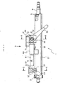
- FIG. 2 is a side view showing the impact absorbing type steering column apparatus in the present embodiment.
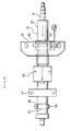
- FIG. 3 is a plan view (taken along the arrow line A in FIG. 2 ) showing the same apparatus.
- a steering column 21 is manufactured by welding an upper distance bracket (which will hereinafter simply called an upper bracket) 25 composed of a steel plate to substantially the central portion of a steel column tube 23 and further welding a lower distance bracket (which will hereinafter simply called a lower bracket) 27 composed of a steel plate to a front portion (the left side in FIGS. 2 and 3 ) of the tube 23.
- an upper distance bracket which will hereinafter simply called an upper bracket
- a lower bracket which will hereinafter simply called a lower bracket
- the upper bracket 25 is held by a tilt bracket 31 as a steel plate welding structural member fixed to the car body sided member 3.
- the upper bracket 25 is forced to be fixed by a predetermined fastening force given by a tilt bolt 33 penetrating the tilt bracket 31 and a nut 35.
- the upper bracket 25 is formed with a substantially U-shaped notch 37 opening backward.
- the tilt bolt 33 is inserted into a front side end of this notch 37.
- members indicated by the numerals 41, 43 are known tilt cams used for fixing the steering column 21 at a predetermined angle.
- a member designated by the numeral 45 is a tilt lever for rotationally driving the tilt cam 41.
- a member indicated by the numeral 47 is a thrust bearing interposed between a head of the tilt bolt 33 and the tilt lever 45.
- the lower bracket 27 is held by a pivot bracket 51 as a casting fixed to the car body sided member 3.
- the lower bracket 27 is fixed by a pivot bolt 53 penetrating a pivot bracket 51 and a nut 55.
- the pivot bracket 51 is formed with a substantially U-shaped notch 57 opening forward.
- the pivot bolt 53 is inserted into a rear side end of this notch 57.
- the steering column 21 is swayable about the pivot bolt 53, and the driver is able to adjust upper and lower positions of the steering wheel 11 within a predetermined range by manipulating the tilt lever 45.
- the collision energy absorbing mechanism is constructed of an energy absorbing plate 61 held by the tilt bolt 33 and a variable drawing device 63 fixed to the steering column 21.
- the energy absorbing plate 61 is a substantially U-shaped steel plate opening forward, and the tilt bolt 33 penetrates a portion vicinal to the rear side end of the plate 61.
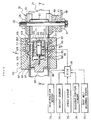
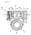
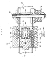
- variable drawing device 63 is, as shown in FIGS. 6 , 7 (a sectional view taken along the line E-E in FIG. 6 ) and 8 (a sectional view taken along the line F-F in FIG. 6 ), constructed of a base plate 65 as a steel plate press molding welded to a column tube 23, a housing 67 fastened with a bolt to the base plate 65, a slide block 69 slidably held within the housing 67, and an electromagnetic actuator (which will hereinafter be termed a solenoid) 71 retained in the housing 67 and driven under control of an ECU (Electronic Control Unit) 70.
- ECU Electronic Control Unit
- the solenoid 71 is constructed of a yoke 81 as a steel plate press molding, a plunger (movable iron core) 83 so held as to be slidable back and forth within the yoke 81, first and second coils 85, 87 disposed in front and in rear so as to surround the plunger 83, a permanent magnet 89 interposed between the two coils 85 and 87, and first and second fixed iron cores 91, 93 fastened and fixed to front and rear inner side end surfaces of the yoke 81.
- a rod member 95 provided at a front side end of the plunger 83 is screw-connected to the slide block 69, whereby the plunger 83 moves back and forth integrally with the slide block 69.
- the first fixed iron core 91 is formed with a through-hole 97 into which the rod member 95 is inserted.
- Members indicated by the numerals 98, 99 in FIG. 6 are buffer members pasted to the slide block 69.
- the buffer members 98, 99 function to restrain a sound of impingement of the slide block 69 upon the housing 67 and the solenoid 71.
- a pair of guide plates 101, 103 provided right and left are held adjacent to both of the side surfaces of the slide block 69.
- the energy absorbing plates 61 are inserted and fitted in between the slide block 69 and these guide plates 101, 103.
- the two guide plates 101, 103 respectively have U-shaped recessed portions 105, 107 formed inwards at substantially the central portion and the rear portion.
- the energy absorbing plates 61 are formed with front and rear U-shaped bent portions 109, 111 fitted in the U-shaped recessed portions 105, 107.
- fixed drawing pins 113 are fitted in the front U-shaped bent portions 109, and movable drawing pins 115 are fitted in the rear U-shaped bent portions 111.
- the housing 67 is formed with a pair of left and right elongate holes 121, 123 for retaining the movable drawing pins 115.
- the movable drawing pins 115 are movable by a predetermined quantity within those elongate holes 121, 123.
- the ECU 70 When the automobile starts traveling, the ECU 70, based on detection signals of the variety of sensors 73 - 77 described above, repeatedly calculates a target operation load of the collision energy absorbing mechanism at a predetermined control interval. For instance, if a weight of the driver is comparatively heavy, or if a car speed is high even though the driver's weight is comparatively light, a kinetic energy of the driver at a collision increases, and therefore the target operation load increases. Then, the ECU 70 outputs an exciting current to a second coil 87 of the solenoid 71, whereby the plunger 83 is, as shown in FIG. 9 , attracted backward by a magnetic force.
- the slide block 69 connected to the plunger 83 moves backward, and a side surface of the rear portion of the block 69 is positioned inwardly of the movable drawing pin 115, thereby restricting a shift to the inside of the movable drawing pin 115.
- the plunger 83 comes into contact with a side end surface of the second fixed iron core 93, however, since the second fixed iron core 93 is connected to the permanent magnet 93 via the yoke 81, the plunger 83 is magnetically adsorbed to the second fixed iron core 93 with a predetermined adsorbing force.
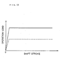
- FIG. 13 is a graph showing a relationship between an operation load and a shift stroke of the steering column 21, wherein the solid line indicates a result of test on that occasion (in the case of the large operation load).
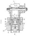
- the ECU 70 outputs the exciting current to the first coil 85 of the solenoid 71 for a predetermined period of time, and, as shown in FIG. 14 , the plunger 83 is attracted forward by the magnetic force.
- the slide block 69 connected to the plunger 83 is thereby shifted forward, and the side surface of the rear portion thereof moves off from the inside of the movable drawing pin 115, whereby the movable drawing pin 115 becomes movable within the elongate holes 121, 123.
- the plunger 83 is brought into contact with the side end surface of the first fixed iron core 91, however, since the first fixed iron core 91 is also connected to the permanent magnet 89 through the yoke 81 as the second fixed iron core 93 is, the plunger 83 is magnetically adsorbed to the first fixed iron core 91 with a predetermined adsorbing force.
- the steering column 21 comes off and advances, and the variable drawing device 63 moves forward with respect to the energy absorbing plate 61.
- the movable drawing pin 115 is not restricted by the slide block 69, and hence, as shown in FIG. 103, the rear U-shaped bent portion 111 of the energy absorbing plate 61, when advancing and getting released from the U-shaped recessed portion 107, presses inwards and moves the movable drawing pin 115 away afterward.
- the energy absorbing plates 61 are drawn only by the fixed drawing pins 113 at the two right and left portions, thereby decreasing a quantity of absorbing the collision energy.
- the steering column 21 smoothly advances, and it never happens that the a large impact is applied upon the breast and the head of the driver.
- the broken line indicates a result of test on this occasion (in the case of the small operation load), and it can be understood that the small operation load significantly decreases with respect to the large operation load.
- the energy absorbing member involves the use of the steel plate
- the drawing member involves the use of the pin.
- a steel wire may be used as the energy absorbing member
- a steel ball etc may also be used as the drawing member.
- the present embodiment takes the configuration in which the first and second fixed iron cores are connected to the single permanent magnet through the yoke, and may also involve the use of two pieces of permanent magnets for retaining the plungers in front and rear positions.
- the energy absorbing plate is fixed to the steering column, while the variable drawing device may be fixed to the car body.
- the specific configurations of the steering column apparatus and of the energy absorption quantity adjusting mechanism and the material and shape of the drawing member may properly be modified within the range of the present invention without departing from the concept of the invention.
- the impact absorbing type steering column apparatus in the present embodiment of the present invention includes the collision energy absorbing mechanism for absorbing the energy of the secondary collision of the occupant upon the collision of the car, and the energy absorption quantity adjusting mechanism for changing the absorption quantity with which the collision energy absorbing mechanism absorbs the secondary collision energy.
- the electromagnetic actuator is used as the driving source of the energy absorption quantity adjusting mechanism, and the plunger of the electromagnetic actuator is adsorptively held in the predetermined position by the permanent magnet. It is therefore feasible to prevent the coil from becoming exothermic and actualize a reduction in consumption of the electric power owing to the electromagnetic actuator's being electrified only when driving the plunger. In addition, it is also possible to avoid the unprepared shift of the plunger due to the vibrations during the traveling of the car and to the impact when collided, and to simplify the structure with the return spring and the failsafe mechanism unnecessary, and further to reduce the costs thereof.
- the energy absorption quantity adjusting mechanism is driven under control of the ECU but may also be so driven as to be switched by the driver's manipulating a manual switch etc.
- a switching mechanism of a mechanical type as well as of an electrically-driven type can be adopted.
- the switching of the calculation may be triggered by an input of a change signal for changing a load setting condition, e.g., by attaching or detaching the seatbelt, adjusting a seat position, changing a car speed, confirming a shift of the gearshift lever from the parking position, and so on.
- a change signal for changing a load setting condition e.g., by attaching or detaching the seatbelt, adjusting a seat position, changing a car speed, confirming a shift of the gearshift lever from the parking position, and so on.
- the specific configurations of the steering column apparatus and of the energy absorption quantity adjusting mechanism may properly be modified within the range of the present invention without departing from the concept of the invention.
Landscapes
- Engineering & Computer Science (AREA)
- Chemical & Material Sciences (AREA)
- Combustion & Propulsion (AREA)
- Transportation (AREA)
- Mechanical Engineering (AREA)
- Steering Controls (AREA)
- Vibration Dampers (AREA)
Claims (4)
- Stoßabsorbierende Lenksäulenvorrichtung (1), umfassend:Stoßenergie absorbierende Mittel (61, 63) zum Absorbieren einer Energie einer sekundären Zusammenstoßenergie eines Insassen bei einem Zusammenstoß eines Fahrzeugs; undEnergieabsorptionsmengeneinstellmittel (69, 70, 71, 83, 85, 87) zum Verändern einer Absorptionsmenge, mit welcher das Stoßenergie absorbierende Mittel die sekundäre Zusammenstoßenergie absorbiert,wobei ein elektromagnetisches Stellglied (71) eine Antriebsquelle des Energieabsorptionsmengeneinstellmittels ist, undein Tauchkolben (83) des elektromagnetischen Stellglieds absorptionsfähig in einer vorbestimmten Position durch einen Permanentmagneten (89) gehalten wird.
- Stoßabsorbierende Lenksäulenvorrichtung (1) gemäß Anspruch 1, wobei das Stoßenergie absorbierende Mittel (61, 63) zwischen einer Lenksäule (21) der stoßabsorbierenden Lenksäulenvorrichtung und einer Halterung auf Seiten der Karosserie (31) vorgesehen ist und eine plastische Verformung eines Energie absorbierenden Elements, welches eine Metallplatte (61) oder einen Metalldraht umfasst, unter Einsatz von Zugmitteln (113, 115) mit einer Verschiebung der Lenksäule verursacht.
- Stoßabsorbierende Lenksäulenvorrichtung (1) gemäß Anspruch 1 oder 2, wobei das Zugmittel eine Metallstange (113, 115) oder eine Metallkugel umfasst, und
das Energieabsorptionsmengeneinstellmittel (69, 70, 71, 83, 85, 87) wenigstens eines von einem plastisch verformten Teil und einer Menge plastischer Verformung des energieabsorbierenden Elements (61) durch das Zugmittel verändert. - Fahrzeug, umfassend eine stoßabsorbierende Lenksäulenvorrichtung (1) gemäß jedem vorangehenden Anspruch.
Applications Claiming Priority (11)
| Application Number | Priority Date | Filing Date | Title |
|---|---|---|---|
| JP2000143646 | 2000-05-16 | ||
| JP2000143646 | 2000-05-16 | ||
| JP2000255886 | 2000-08-25 | ||
| JP2000255886 | 2000-08-25 | ||
| JP2000266950 | 2000-09-04 | ||
| JP2000266950A JP2002067980A (ja) | 2000-09-04 | 2000-09-04 | 衝撃吸収式ステアリングコラム装置 |
| JP2000307709A JP4524899B2 (ja) | 2000-10-06 | 2000-10-06 | 衝撃吸収式ステアリングコラム装置 |
| JP2000307709 | 2000-10-06 | ||
| JP2001085183 | 2001-03-23 | ||
| JP2001085183A JP2002137743A (ja) | 2000-05-16 | 2001-03-23 | 衝撃吸収式ステアリングコラム装置 |
| EP01304351A EP1155940B1 (de) | 2000-05-16 | 2001-05-16 | Stossabsorbierende Lenkung |
Related Parent Applications (1)
| Application Number | Title | Priority Date | Filing Date |
|---|---|---|---|
| EP01304351A Division EP1155940B1 (de) | 2000-05-16 | 2001-05-16 | Stossabsorbierende Lenkung |
Publications (3)
| Publication Number | Publication Date |
|---|---|
| EP1553004A2 EP1553004A2 (de) | 2005-07-13 |
| EP1553004A3 EP1553004A3 (de) | 2005-07-20 |
| EP1553004B1 true EP1553004B1 (de) | 2009-03-18 |
Family
ID=27531530
Family Applications (3)
| Application Number | Title | Priority Date | Filing Date |
|---|---|---|---|
| EP05005947A Withdrawn EP1555188A1 (de) | 2000-05-16 | 2001-05-16 | Stossabsorbierende Lenkung |
| EP05004757A Expired - Lifetime EP1553004B1 (de) | 2000-05-16 | 2001-05-16 | Stossabsorbierende Lenkung |
| EP01304351A Expired - Lifetime EP1155940B1 (de) | 2000-05-16 | 2001-05-16 | Stossabsorbierende Lenkung |
Family Applications Before (1)
| Application Number | Title | Priority Date | Filing Date |
|---|---|---|---|
| EP05005947A Withdrawn EP1555188A1 (de) | 2000-05-16 | 2001-05-16 | Stossabsorbierende Lenkung |
Family Applications After (1)
| Application Number | Title | Priority Date | Filing Date |
|---|---|---|---|
| EP01304351A Expired - Lifetime EP1155940B1 (de) | 2000-05-16 | 2001-05-16 | Stossabsorbierende Lenkung |
Country Status (3)
| Country | Link |
|---|---|
| US (4) | US6726248B2 (de) |
| EP (3) | EP1555188A1 (de) |
| DE (2) | DE60125456T2 (de) |
Families Citing this family (36)
| Publication number | Priority date | Publication date | Assignee | Title |
|---|---|---|---|---|
| FR2834958B1 (fr) * | 2002-01-23 | 2004-07-16 | Faurecia Ind | Dispositif reglable d'amortissement de choc pour colonne de direction de vehicule automobile, colonne de direction et vehicule automobile comprenant un tel dispositif |
| JP2003276544A (ja) * | 2002-03-20 | 2003-10-02 | Toyota Motor Corp | 乗員保護装置 |
| US7331608B2 (en) * | 2002-06-27 | 2008-02-19 | Delphi Technologies, Inc. | Electrically actuated steering column mechanism |
| JP4124021B2 (ja) * | 2002-10-07 | 2008-07-23 | トヨタ自動車株式会社 | 衝撃吸収式ステアリングコラム装置 |
| JP2004203164A (ja) * | 2002-12-25 | 2004-07-22 | Fuji Kiko Co Ltd | 車両用ステアリング装置の衝撃吸収構造 |
| JP4449600B2 (ja) * | 2004-06-28 | 2010-04-14 | アイシン精機株式会社 | 衝撃吸収式ステアリング装置 |
| US20060042458A1 (en) * | 2004-09-02 | 2006-03-02 | Krj Industria E Comercio Ltda. | Device applied in electronic connectors of energy provided with unit of detonation incorporated in a button for detonation of cartridge with powder |
| US7334817B2 (en) * | 2004-09-02 | 2008-02-26 | Delphi Technologies, Inc. | Active energy absorption method using tilt and telescope positions |
| US7278660B2 (en) * | 2004-10-07 | 2007-10-09 | Delphi Technologies, Inc. | Rake and telescope column lock safety function |
| US7347451B2 (en) * | 2004-12-16 | 2008-03-25 | Delphi Technologies, Inc. | Pre-crash column release |
| US7264274B2 (en) * | 2005-06-22 | 2007-09-04 | Delphi Technologies, Inc. | Tuneable energy absorbing mounting structure for steering column |
| US20100156081A1 (en) * | 2005-10-06 | 2010-06-24 | Hyundai Motor Company | Impact absorbing device for steering column of vehicle |
| US7497470B2 (en) * | 2005-11-21 | 2009-03-03 | Delphi Technologies, Inc. | Energy absorbing apparatus |
| DE102006020650B3 (de) * | 2006-05-02 | 2007-08-23 | Thyssenkrupp Presta Ag | Lenksäule für ein Kraftfahrzeug |
| US7604255B2 (en) * | 2006-05-25 | 2009-10-20 | Trw Automotive U.S. Llc | Steering column release mechanism |
| JP4784828B2 (ja) * | 2006-06-13 | 2011-10-05 | 株式会社ジェイテクト | 車両用操舵装置 |
| US7780196B2 (en) * | 2006-10-05 | 2010-08-24 | Gm Global Technology Operations, Inc. | Energy absorbing steering column assembly |
| KR100848497B1 (ko) * | 2007-01-19 | 2008-07-28 | 주식회사 만도 | 와이어 블록 어셈블리를 구비한 자동차의 충격 흡수식조향컬럼 |
| JP2009119999A (ja) * | 2007-11-14 | 2009-06-04 | Toyota Motor Corp | 車両用ステアリングコラム装置 |
| KR101115084B1 (ko) * | 2008-02-29 | 2012-02-28 | 주식회사 만도 | 자동차의 충격 흡수식 조향 컬럼 |
| GB0816354D0 (en) * | 2008-09-06 | 2008-10-15 | Trw Ltd | Steering column assembly |
| DE102009044966A1 (de) * | 2009-09-24 | 2011-03-31 | Robert Bosch Gmbh | Vorrichtung und Verfahren zum adaptiven Abbau von Crashenergie |
| DE102010002904A1 (de) * | 2010-03-16 | 2011-09-22 | Robert Bosch Gmbh | Aktuator und Verfahren zur Adaption einer Steifigkeit eines Deformationselementes |
| DE102010020088B4 (de) * | 2010-05-10 | 2013-06-27 | Thyssenkrupp Presta Aktiengesellschaft | Verfahren und Vorrichtung zur Regelung eines steuerbaren Energieabsorbers |
| US8899622B2 (en) | 2012-03-09 | 2014-12-02 | Nsk Americas, Inc. | Internally collapsible steering column assembly |
| US8915521B2 (en) * | 2013-03-15 | 2014-12-23 | Steering Solutions Ip Holding Corporation | Steering column telescoping bushing with roller springs |
| CN103171610B (zh) * | 2013-03-22 | 2016-01-13 | 上海航天汽车机电股份有限公司 | 汽车转向管柱连接支架用吸能结构 |
| PL3052370T3 (pl) | 2013-10-04 | 2017-12-29 | Nsk Americas, Inc. | Składany zespół kolumny kierownicy |
| US9421995B2 (en) * | 2013-10-30 | 2016-08-23 | Nsk Ltd. | Steering device |
| BE1022076B1 (fr) * | 2014-01-29 | 2016-02-15 | Cockerill Maintenance & Ingenierie Sa | Dispositif d'attenuation d'impact |
| CN105980236A (zh) | 2014-02-27 | 2016-09-28 | Kyb株式会社 | 转向装置 |
| JP6602155B2 (ja) * | 2015-10-23 | 2019-11-06 | 富士機工株式会社 | ステアリングコラム装置 |
| JP7057548B2 (ja) | 2016-09-27 | 2022-04-20 | 日本精工株式会社 | 内部衝撃吸収ステアリングコラム組立体のためのエネルギー吸収デバイス |
| US10654511B1 (en) * | 2018-10-31 | 2020-05-19 | GM Global Technology Operations LLC | Methods for steering system impedance control |
| DE102019004840A1 (de) | 2019-07-12 | 2021-01-14 | Thyssenkrupp Ag | Verfahren zum Betreiben einer motorisch verstellbaren Lenksäule und motorisch verstellbare Lenksäule für ein Kraftfahrzeug |
| IT202300016056A1 (it) * | 2023-07-28 | 2025-01-28 | Andrea Mattei | Apparato per il comando di sterzo di veicolo a geometria variabile con assorbimento d'urto |
Family Cites Families (30)
| Publication number | Priority date | Publication date | Assignee | Title |
|---|---|---|---|---|
| JPS4635527Y1 (de) | 1966-11-28 | 1971-12-07 | ||
| DE2417543A1 (de) * | 1974-04-10 | 1975-10-30 | Porsche Ag | Sicherheits- lenkungsanordnung fuer kraftfahrzeuge, insb. fuer personenkraftwagen |
| DE3616246A1 (de) | 1986-05-14 | 1987-11-19 | Porsche Ag | Lenksaeulenbefestigung fuer ein kraftfahrzeug |
| US4805478A (en) | 1987-06-26 | 1989-02-21 | General Motors Corporation | Steering column for vehicle with multitube energy absorbing mast jacket |
| US4886295A (en) * | 1988-12-05 | 1989-12-12 | General Motors Corporation | Vehicle occupant protection system |
| US4994776A (en) * | 1989-07-12 | 1991-02-19 | Babcock, Inc. | Magnetic latching solenoid |
| KR920006358B1 (ko) | 1990-04-30 | 1992-08-03 | 주식회사 금성사 | 세탁기의 예약 시스템 |
| JP2829199B2 (ja) | 1992-08-07 | 1998-11-25 | 株式会社山田製作所 | ステアリングコラムの衝撃吸収装置 |
| JPH07257400A (ja) | 1994-03-25 | 1995-10-09 | Nippon Seiko Kk | 衝撃吸収式ステアリングコラム装置用エネルギ吸収部材 |
| JPH07329796A (ja) | 1994-06-06 | 1995-12-19 | Nippon Seiko Kk | 衝撃吸収式ステアリング装置用エネルギ吸収プレート |
| DE19542491C1 (de) * | 1995-11-15 | 1997-02-27 | Daimler Benz Ag | Sicherheitslenksäule für Kraftfahrzeuge |
| SE507771C2 (sv) | 1996-11-21 | 1998-07-13 | Volvo Ab | Anordning och förfarande för skydd av åkande i fordon |
| JP3988200B2 (ja) * | 1997-03-14 | 2007-10-10 | 株式会社ジェイテクト | 衝撃吸収式ステアリング装置 |
| ES2207763T3 (es) * | 1997-04-16 | 2004-06-01 | Volkswagen Aktiengesellschaft | Columna de direccion para dispositivos de proteccion de pasajeros y direcciones de seguridad. |
| US6040752A (en) * | 1997-04-22 | 2000-03-21 | Fisher; Jack E. | Fail-safe actuator with two permanent magnets |
| SE510856C2 (sv) * | 1997-06-23 | 1999-06-28 | Volvo Ab | Kraftupptagande anordning för skydd av åkande i fordon |
| GB9716747D0 (en) * | 1997-08-08 | 1997-10-15 | Lucas Ind Plc | Improvements relating to steering assemblies |
| DE19749970A1 (de) * | 1997-11-05 | 1999-05-12 | Petri Ag | Insassen-Sicherheitsvorrichtung für die Fahrerseite eines Kraftfahrzeuges |
| JP3612971B2 (ja) * | 1997-12-03 | 2005-01-26 | 日本精工株式会社 | 衝撃吸収式ステアリングコラム装置 |
| DE19803156C1 (de) * | 1998-01-28 | 1999-08-12 | Daimler Chrysler Ag | Energieabsorbierende Deformationsanordnung |
| CN1303340A (zh) * | 1998-05-11 | 2001-07-11 | 伊诺瓦技术开发有限责任公司 | 汽车安全转向柱、安全系统和带安全系统的汽车及安全方法 |
| GB9817536D0 (en) * | 1998-08-13 | 1998-10-07 | Rover Group | A motor vehicle |
| FR2788029B1 (fr) * | 1999-01-06 | 2001-02-23 | Lemforder Nacam Sa | Dispositif d'absorption modulable d'energie d'une colonne de direction de vehicule automobile |
| GB2350328B (en) | 1999-05-26 | 2002-07-17 | Nastech Europ Ltd | Collapsible steering column assembly |
| US6322103B1 (en) * | 1999-06-11 | 2001-11-27 | Delphi Technologies, Inc. | Energy absorber for motor vehicle steering column |
| US6152488A (en) * | 1999-06-16 | 2000-11-28 | Ford Global Technologies, Inc. | Steering column with variable collapse force |
| US6394241B1 (en) * | 1999-10-21 | 2002-05-28 | Simula, Inc. | Energy absorbing shear strip bender |
| US6296280B1 (en) * | 1999-11-02 | 2001-10-02 | Trw Inc. | Adaptive collapsible steering column |
| US6189929B1 (en) * | 1999-11-02 | 2001-02-20 | Trw Inc. | Adaptive collapsible steering column |
| US6279952B1 (en) * | 2000-01-14 | 2001-08-28 | Trw Inc. | Adaptive collapsible steering column |
-
2001
- 2001-05-15 US US09/855,637 patent/US6726248B2/en not_active Expired - Lifetime
- 2001-05-16 EP EP05005947A patent/EP1555188A1/de not_active Withdrawn
- 2001-05-16 EP EP05004757A patent/EP1553004B1/de not_active Expired - Lifetime
- 2001-05-16 EP EP01304351A patent/EP1155940B1/de not_active Expired - Lifetime
- 2001-05-16 DE DE60125456T patent/DE60125456T2/de not_active Expired - Lifetime
- 2001-05-16 DE DE60138050T patent/DE60138050D1/de not_active Expired - Lifetime
-
2004
- 2004-01-15 US US10/757,418 patent/US7070206B2/en not_active Expired - Lifetime
- 2004-01-16 US US10/758,414 patent/US20040150207A1/en not_active Abandoned
-
2006
- 2006-03-17 US US11/377,440 patent/US7198297B2/en not_active Expired - Lifetime
Also Published As
| Publication number | Publication date |
|---|---|
| EP1553004A3 (de) | 2005-07-20 |
| DE60138050D1 (de) | 2009-04-30 |
| US7070206B2 (en) | 2006-07-04 |
| US20040150207A1 (en) | 2004-08-05 |
| DE60125456D1 (de) | 2007-02-08 |
| US20020011724A1 (en) | 2002-01-31 |
| EP1155940A3 (de) | 2004-01-14 |
| US20040145169A1 (en) | 2004-07-29 |
| EP1155940B1 (de) | 2006-12-27 |
| US7198297B2 (en) | 2007-04-03 |
| EP1155940A2 (de) | 2001-11-21 |
| EP1553004A2 (de) | 2005-07-13 |
| US20060163862A1 (en) | 2006-07-27 |
| US6726248B2 (en) | 2004-04-27 |
| EP1555188A1 (de) | 2005-07-20 |
| DE60125456T2 (de) | 2007-10-04 |
Similar Documents
| Publication | Publication Date | Title |
|---|---|---|
| US7198297B2 (en) | Impact absorbing type steering column apparatus | |
| US6631924B2 (en) | Shock absorbing type steering column apparatus | |
| GB2331964A (en) | Impact absorbing steering column device | |
| JP2003237594A (ja) | 自動車用ステアリング・コラム装置 | |
| JP2002137743A (ja) | 衝撃吸収式ステアリングコラム装置 | |
| JPH01254470A (ja) | ステアリング支持装置 | |
| JPH03136972A (ja) | ステアリングコラムの衝撃吸収装置 | |
| JP3725762B2 (ja) | 衝撃吸収式電動パワーステアリング装置 | |
| JP4524899B2 (ja) | 衝撃吸収式ステアリングコラム装置 | |
| JP5212403B2 (ja) | ステアリング装置 | |
| JP2002067980A (ja) | 衝撃吸収式ステアリングコラム装置 | |
| JP4478035B2 (ja) | 車両用の可動式バンパ装置 | |
| JP2002362380A (ja) | 衝撃吸収式ステアリングコラム装置 | |
| JP2008132986A (ja) | 衝撃吸収式ステアリングコラム装置 | |
| JP2002225728A (ja) | 衝撃吸収式ステアリングコラム装置 | |
| JP3749419B2 (ja) | ステアリング装置 | |
| JP2002120734A (ja) | 衝撃吸収式ステアリングコラム装置 | |
| JP2005067264A (ja) | 車両用衝撃吸収式ステアリングコラム装置 | |
| JP2008189028A (ja) | 車両用パワープラントのマウント装置 | |
| JP2005126059A (ja) | 車両用衝撃吸収式ステアリングコラム装置 | |
| KR200148303Y1 (ko) | 자동차핸들의 충격 흡수장치 | |
| JP2002114157A (ja) | 衝撃吸収式ステアリングコラム装置 | |
| JP2009202700A (ja) | 衝撃吸収式ステアリングコラム装置 | |
| JP4019514B2 (ja) | 車両用ステアリング装置の一次ストロークストッパ | |
| JP2014034349A (ja) | 車両用繰出装置 |
Legal Events
| Date | Code | Title | Description |
|---|---|---|---|
| PUAI | Public reference made under article 153(3) epc to a published international application that has entered the european phase |
Free format text: ORIGINAL CODE: 0009012 |
|
| PUAL | Search report despatched |
Free format text: ORIGINAL CODE: 0009013 |
|
| AC | Divisional application: reference to earlier application |
Ref document number: 1155940 Country of ref document: EP Kind code of ref document: P |
|
| AK | Designated contracting states |
Kind code of ref document: A2 Designated state(s): DE GB |
|
| AK | Designated contracting states |
Kind code of ref document: A3 Designated state(s): DE GB |
|
| 17P | Request for examination filed |
Effective date: 20050901 |
|
| AKX | Designation fees paid |
Designated state(s): DE GB |
|
| GRAP | Despatch of communication of intention to grant a patent |
Free format text: ORIGINAL CODE: EPIDOSNIGR1 |
|
| GRAS | Grant fee paid |
Free format text: ORIGINAL CODE: EPIDOSNIGR3 |
|
| GRAA | (expected) grant |
Free format text: ORIGINAL CODE: 0009210 |
|
| AC | Divisional application: reference to earlier application |
Ref document number: 1155940 Country of ref document: EP Kind code of ref document: P |
|
| AK | Designated contracting states |
Kind code of ref document: B1 Designated state(s): DE GB |
|
| REG | Reference to a national code |
Ref country code: GB Ref legal event code: FG4D |
|
| REF | Corresponds to: |
Ref document number: 60138050 Country of ref document: DE Date of ref document: 20090430 Kind code of ref document: P |
|
| PLBE | No opposition filed within time limit |
Free format text: ORIGINAL CODE: 0009261 |
|
| STAA | Information on the status of an ep patent application or granted ep patent |
Free format text: STATUS: NO OPPOSITION FILED WITHIN TIME LIMIT |
|
| 26N | No opposition filed |
Effective date: 20091221 |
|
| PGFP | Annual fee paid to national office [announced via postgrant information from national office to epo] |
Ref country code: GB Payment date: 20180329 Year of fee payment: 18 |
|
| PGFP | Annual fee paid to national office [announced via postgrant information from national office to epo] |
Ref country code: DE Payment date: 20180502 Year of fee payment: 18 |
|
| REG | Reference to a national code |
Ref country code: DE Ref legal event code: R119 Ref document number: 60138050 Country of ref document: DE |
|
| GBPC | Gb: european patent ceased through non-payment of renewal fee |
Effective date: 20190516 |
|
| PG25 | Lapsed in a contracting state [announced via postgrant information from national office to epo] |
Ref country code: DE Free format text: LAPSE BECAUSE OF NON-PAYMENT OF DUE FEES Effective date: 20191203 Ref country code: GB Free format text: LAPSE BECAUSE OF NON-PAYMENT OF DUE FEES Effective date: 20190516 |