EP1550853A1 - Biochemischer behälter - Google Patents
Biochemischer behälter Download PDFInfo
- Publication number
- EP1550853A1 EP1550853A1 EP03728113A EP03728113A EP1550853A1 EP 1550853 A1 EP1550853 A1 EP 1550853A1 EP 03728113 A EP03728113 A EP 03728113A EP 03728113 A EP03728113 A EP 03728113A EP 1550853 A1 EP1550853 A1 EP 1550853A1
- Authority
- EP
- European Patent Office
- Prior art keywords
- vessel
- biochemical
- plate
- glass
- ultraviolet
- Prior art date
- Legal status (The legal status is an assumption and is not a legal conclusion. Google has not performed a legal analysis and makes no representation as to the accuracy of the status listed.)
- Withdrawn
Links
- VYPSYNLAJGMNEJ-UHFFFAOYSA-N Silicium dioxide Chemical compound O=[Si]=O VYPSYNLAJGMNEJ-UHFFFAOYSA-N 0.000 claims abstract description 61
- 239000000377 silicon dioxide Substances 0.000 claims abstract description 26
- 235000012239 silicon dioxide Nutrition 0.000 claims abstract description 22
- 229920003002 synthetic resin Polymers 0.000 claims abstract description 20
- 239000000057 synthetic resin Substances 0.000 claims abstract description 20
- 238000000034 method Methods 0.000 claims abstract description 19
- 239000011521 glass Substances 0.000 claims description 90
- 239000000758 substrate Substances 0.000 claims description 61
- 230000002093 peripheral effect Effects 0.000 claims description 14
- 239000000853 adhesive Substances 0.000 claims description 13
- 230000001070 adhesive effect Effects 0.000 claims description 13
- 229910010272 inorganic material Inorganic materials 0.000 claims description 12
- 239000011147 inorganic material Substances 0.000 claims description 12
- 229910052751 metal Inorganic materials 0.000 claims description 9
- 239000002184 metal Substances 0.000 claims description 9
- 239000007791 liquid phase Substances 0.000 claims description 6
- 229910000679 solder Inorganic materials 0.000 claims description 4
- 239000003960 organic solvent Substances 0.000 abstract description 26
- 238000000870 ultraviolet spectroscopy Methods 0.000 abstract description 18
- 238000004611 spectroscopical analysis Methods 0.000 description 12
- 239000007864 aqueous solution Substances 0.000 description 9
- 238000004458 analytical method Methods 0.000 description 8
- 230000005540 biological transmission Effects 0.000 description 7
- 238000010276 construction Methods 0.000 description 7
- 239000000919 ceramic Substances 0.000 description 5
- 238000012252 genetic analysis Methods 0.000 description 4
- 238000004519 manufacturing process Methods 0.000 description 4
- 239000000463 material Substances 0.000 description 4
- 229920005990 polystyrene resin Polymers 0.000 description 4
- 239000005361 soda-lime glass Substances 0.000 description 4
- 239000005388 borosilicate glass Substances 0.000 description 3
- 239000011248 coating agent Substances 0.000 description 3
- 238000000576 coating method Methods 0.000 description 3
- 239000000693 micelle Substances 0.000 description 3
- 238000000465 moulding Methods 0.000 description 3
- 238000005498 polishing Methods 0.000 description 3
- 229920005989 resin Polymers 0.000 description 3
- 239000011347 resin Substances 0.000 description 3
- XLYOFNOQVPJJNP-UHFFFAOYSA-N water Substances O XLYOFNOQVPJJNP-UHFFFAOYSA-N 0.000 description 3
- KRHYYFGTRYWZRS-UHFFFAOYSA-N Fluorane Chemical compound F KRHYYFGTRYWZRS-UHFFFAOYSA-N 0.000 description 2
- NBIIXXVUZAFLBC-UHFFFAOYSA-N Phosphoric acid Chemical compound OP(O)(O)=O NBIIXXVUZAFLBC-UHFFFAOYSA-N 0.000 description 2
- 229910052782 aluminium Inorganic materials 0.000 description 2
- XAGFODPZIPBFFR-UHFFFAOYSA-N aluminium Chemical compound [Al] XAGFODPZIPBFFR-UHFFFAOYSA-N 0.000 description 2
- 239000010453 quartz Substances 0.000 description 2
- 229920006395 saturated elastomer Polymers 0.000 description 2
- 239000013585 weight reducing agent Substances 0.000 description 2
- 229910003638 H2SiF6 Inorganic materials 0.000 description 1
- 229910003947 H3AlF6 Inorganic materials 0.000 description 1
- NHTMVDHEPJAVLT-UHFFFAOYSA-N Isooctane Chemical compound CC(C)CC(C)(C)C NHTMVDHEPJAVLT-UHFFFAOYSA-N 0.000 description 1
- 239000002253 acid Substances 0.000 description 1
- 238000004026 adhesive bonding Methods 0.000 description 1
- 229910000147 aluminium phosphate Inorganic materials 0.000 description 1
- 238000005229 chemical vapour deposition Methods 0.000 description 1
- 238000005520 cutting process Methods 0.000 description 1
- 238000000151 deposition Methods 0.000 description 1
- JVSWJIKNEAIKJW-UHFFFAOYSA-N dimethyl-hexane Natural products CCCCCC(C)C JVSWJIKNEAIKJW-UHFFFAOYSA-N 0.000 description 1
- 238000004090 dissolution Methods 0.000 description 1
- 230000000694 effects Effects 0.000 description 1
- 238000010438 heat treatment Methods 0.000 description 1
- XLYOFNOQVPJJNP-ZSJDYOACSA-N heavy water Substances [2H]O[2H] XLYOFNOQVPJJNP-ZSJDYOACSA-N 0.000 description 1
- 238000009396 hybridization Methods 0.000 description 1
- 239000007788 liquid Substances 0.000 description 1
- 238000003754 machining Methods 0.000 description 1
- 230000035515 penetration Effects 0.000 description 1
- 238000009877 rendering Methods 0.000 description 1
- 239000000741 silica gel Substances 0.000 description 1
- 229910002027 silica gel Inorganic materials 0.000 description 1
- 239000000243 solution Substances 0.000 description 1
- ZEFWRWWINDLIIV-UHFFFAOYSA-N tetrafluorosilane;dihydrofluoride Chemical compound F.F.F[Si](F)(F)F ZEFWRWWINDLIIV-UHFFFAOYSA-N 0.000 description 1
- 238000009281 ultraviolet germicidal irradiation Methods 0.000 description 1
Images


Classifications
-
- B—PERFORMING OPERATIONS; TRANSPORTING
- B01—PHYSICAL OR CHEMICAL PROCESSES OR APPARATUS IN GENERAL
- B01L—CHEMICAL OR PHYSICAL LABORATORY APPARATUS FOR GENERAL USE
- B01L3/00—Containers or dishes for laboratory use, e.g. laboratory glassware; Droppers
- B01L3/50—Containers for the purpose of retaining a material to be analysed, e.g. test tubes
- B01L3/508—Containers for the purpose of retaining a material to be analysed, e.g. test tubes rigid containers not provided for above
- B01L3/5085—Containers for the purpose of retaining a material to be analysed, e.g. test tubes rigid containers not provided for above for multiple samples, e.g. microtitration plates
-
- G—PHYSICS
- G01—MEASURING; TESTING
- G01N—INVESTIGATING OR ANALYSING MATERIALS BY DETERMINING THEIR CHEMICAL OR PHYSICAL PROPERTIES
- G01N21/00—Investigating or analysing materials by the use of optical means, i.e. using sub-millimetre waves, infrared, visible or ultraviolet light
- G01N21/01—Arrangements or apparatus for facilitating the optical investigation
- G01N21/03—Cuvette constructions
- G01N21/09—Cuvette constructions adapted to resist hostile environments or corrosive or abrasive materials
-
- G—PHYSICS
- G01—MEASURING; TESTING
- G01N—INVESTIGATING OR ANALYSING MATERIALS BY DETERMINING THEIR CHEMICAL OR PHYSICAL PROPERTIES
- G01N21/00—Investigating or analysing materials by the use of optical means, i.e. using sub-millimetre waves, infrared, visible or ultraviolet light
- G01N21/17—Systems in which incident light is modified in accordance with the properties of the material investigated
- G01N21/25—Colour; Spectral properties, i.e. comparison of effect of material on the light at two or more different wavelengths or wavelength bands
- G01N21/31—Investigating relative effect of material at wavelengths characteristic of specific elements or molecules, e.g. atomic absorption spectrometry
- G01N21/33—Investigating relative effect of material at wavelengths characteristic of specific elements or molecules, e.g. atomic absorption spectrometry using ultraviolet light
-
- B—PERFORMING OPERATIONS; TRANSPORTING
- B01—PHYSICAL OR CHEMICAL PROCESSES OR APPARATUS IN GENERAL
- B01L—CHEMICAL OR PHYSICAL LABORATORY APPARATUS FOR GENERAL USE
- B01L2300/00—Additional constructional details
- B01L2300/16—Surface properties and coatings
-
- B—PERFORMING OPERATIONS; TRANSPORTING
- B01—PHYSICAL OR CHEMICAL PROCESSES OR APPARATUS IN GENERAL
- B01L—CHEMICAL OR PHYSICAL LABORATORY APPARATUS FOR GENERAL USE
- B01L2300/00—Additional constructional details
- B01L2300/16—Surface properties and coatings
- B01L2300/168—Specific optical properties, e.g. reflective coatings
-
- G—PHYSICS
- G01—MEASURING; TESTING
- G01N—INVESTIGATING OR ANALYSING MATERIALS BY DETERMINING THEIR CHEMICAL OR PHYSICAL PROPERTIES
- G01N21/00—Investigating or analysing materials by the use of optical means, i.e. using sub-millimetre waves, infrared, visible or ultraviolet light
- G01N21/01—Arrangements or apparatus for facilitating the optical investigation
- G01N21/03—Cuvette constructions
- G01N2021/0378—Shapes
- G01N2021/0382—Frustoconical, tapered cell
Definitions
- the present invention relates to a vessel for biochemical use.
- This type of vessel for biochemical use is often employed for analysis or culture of DNA, etc. In this field, it is required to effect the analysis, culture or the like on a great number of samples. For this reason, to allow the analysis or culture of a plurality of kinds of sample by a single vessel, there is generally employed a biochemical vessel (e.g. a microplate) configured to have a plurality of sample wells.
- a biochemical vessel e.g. a microplate
- samples thereof are prepared in the form of an organic solvent (e.g. isooctane), not aqueous solution.
- an organic solvent e.g. isooctane
- the above-described conventionally employed biochemical vessel made of a synthetic resin such as polystyrene resin causes a problem of non-reusability since the resin tends to be dissolved by the organic solvent. Therefore, there is a growing need for a biochemical vessel having high resistance for organic solvents.
- the present invention has been made in view of the above-described state of the art. Its object is to provide a biochemical vessel which has high organic solvent resistance and which can be easily manufactured and allows the ultraviolet spectrometry.
- the vessel comprises a synthetic resin vessel body having ultraviolet transparency and forming a plurality of recesses side by side and at least inner face portions of the plurality of recesses are coated with a silicon dioxide film.
- sample receiving portions As the inner face portions of the plurality of recesses are coated with a silicon dioxide film having high organic solvent resistance, by receiving e.g. samples made of an organic solvent in these portions (referred to as “sample receiving portions"), the vessel can be reused repeatedly without being dissolved.
- the synthetic resin vessel body forming the plurality of recesses side by side can be made easily of a synthetic resin having ultraviolet transparency and the inner face portions of its recesses can be coated with a silicon dioxide film by a desired method. Therefore, the biochemical vessel having the invention's characterizing feature can be manufactured easily.
- this synthetic resin vessel body and the silicon dioxide film both have good ultraviolet transparency, the ultraviolet spectrometry can be effectively carried out on the samples received in the sample receiving recesses.
- the silicon dioxide film is formed by a liquid phase method.
- the silicon dioxide film is formed by a liquid phase method, the film can easily be coated with a uniform thickness on the inner face portions of the plural recesses.
- the spectrometry such as ultraviolet spectrometry can be carried out with high precision advantageously.
- the vessel comprises a glass substrate having ultraviolet transparency and a plurality of cylindrical members formed of an inorganic material, the cylindrical members being attached erect on the substrate via an inorganic adhesive.
- the vessel can be formed by attaching erect a plurality of cylindrical members formed of an inorganic material on a glass substrate having ultraviolet transparency via an inorganic adhesive. Therefore, the vessel can be manufactured easily. Moreover, if e.g. a sample made of an organic solvent is received within a space delimited by each cylindrical member attached erect and the glass substrate, a plurality of samples can be received without being mixed and the vessel can be reused repeatedly without being dissolved. Further, since the glass substrate has ultraviolet transparency, the ultraviolet spectrometry can be carried out on the sample received within a space delimited by each cylindrical member attached erect and the glass substrate.
- this vessel can be advantageously employed as e.g. a determination plate for a microplate reader.
- the vessel comprises a glass substrate having ultraviolet transparency and a plate-like body formed of an inorganic material and defining a plurality of through holes along a thickness thereof, said plate-like body being bonded to the substrate via an inorganic adhesive.
- the vessel can easily be formed by bonding the plate-like body formed of an inorganic material to the glass substrate via the inorganic adhesive. Hence, the vessel can be manufactured easily.
- the plate-like body to be bonded defines a plurality of through holes along a thickness thereof, if e.g. a sample made of an organic solvent is received within a space delimited by each through hole and the glass substrate, a plurality of samples can be received without being mixed and the vessel can be reused repeatedly without being dissolved.
- the glass substrate has ultraviolet transparency, the ultraviolet spectrometry can be carried out on the sample received within a space delimited by each through hole and the glass substrate.
- this vessel can be advantageously employed as e.g. a determination plate for a microplate reader.
- At least one of said plate-like body and said glass substrate defines a concave portion to form a hollow portion in said plate-like body and/or said glass substrate when the plate-like body and the glass substrate are bonded to each other.
- the biochemical vessel comprising the glass substrate and the plate-like body formed of an inorganic material bonded to the substrate is heavy and difficult to handle and has poor work efficiency, compared with a biochemical vessel formed of a resin.
- the vessel can be formed lighter.
- this biochemical vessel can have high organic solvent resistance and be manufactured easily and allows the ultraviolet spectrometry, yet, this can be readily handled by an automatic determining device such as a microplate reader, whereby the work efficiency can be improved.
- said inorganic adhesive comprises a low-melting-point glass or a metal solder.
- the vessel Since the low-melting-point glass or the metal solder has high organic solvent resistance, the vessel will not be dissolved by e.g. a sample made of an organic solvent. And, even if the vessel is reused repeatedly, a plurality of samples can be reliably received in the vessel without being mixed, advantageously.
- the vessel comprises an ultraviolet transparent glass molded product defining a plurality of holes disposed side by side and each having a flat bottom face.
- the vessel can be formed by introducing ultraviolet transparent glass under its melted or softened condition into a predetermined mold and then machining the glass to define a plurality of holes disposed side by side and having flat bottom faces.
- the vessel can be manufactured easily.
- the vessel is formed of the ultraviolet transparent glass, when e.g. samples made of organic solvent are received in its holes, the vessel is not dissolved and the ultraviolet spectrometry can be carried out effectively.
- these plurality of holes have flat bottom faces, when a visible light beam, a ultraviolet beam, an X ray or the like used in the spectrometry is caused to enter this bottom face along the vertical direction, the spectrometry can be carried out with high precision advantageously.
- this vessel can be advantageously employed as e.g. a determination plate for a microplate reader.
- said holes are tapered from their openings toward their bottom faces.
- the vessel can be washed easily to be advantageous for its reuse. Also, the vessel can be molded easily.
- the vessel comprises a plate-like substrate defining a plurality of through holes along its thickness and a ultraviolet transparent glass container received within each said through hole, with an outer peripheral face of the glass container being fixed in a gapless manner to an inner peripheral face of said through hole.
- a plurality of through holes are defined in a plate-like substrate and a ultraviolet transparent glass container is received within each of the through holes, with an outer peripheral face of the glass container being fixed in a gapless manner to an inner peripheral face of said through hole. Therefore, by receiving a sample made of e.g. organic solvent in the glass container, the vessel can be reused repeatedly without being dissolved for example. Further, since the ultraviolet transparent glass container is received within each through hole defined in the plate-like substrate with the bottom of the glass container facing the lower face, the ultraviolet transparency can be ensured, without particularly limiting the material to form the plate-like substrate. Hence, the biochemical vessel having this feature can be manufactured easily and the ultraviolet spectrometry can be carried out effectively on the sample received within the glass container.
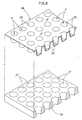
- Figs. 1(A) and (B) show an example of the first embodiment of the present invention.
- Fig. 1 (A) is a perspective view showing an entire biochemical vessel and Fig. 1 (B) is its partially enlarged section view.
- this biochemical vessel is formed by coating an outer side of a synthetic resin vessel body 10 with a silicon dioxide film 11.
- This synthetic resin vessel body 10 comprises a substantially rectangular body as a whole consisting of a number of recesses 12 and wall portions 13, the recesses 12 being provided as cylindrical portions disposed side by side and extending along the vertical direction. And, as shown in the figure, the many recesses 12 are partitioned from each other by the wall portions 13.
- this biochemical vessel includes many cells (s) formed by coating the insides of the recesses 12 with the silicon dioxide film 11.
- cells (s) formed by coating the insides of the recesses 12 with the silicon dioxide film 11.
- various analyses or culture of DNA can be carried out.
- 8 x 12 96 cells (s) are formed as an example.
- the synthetic resin vessel body 10 is formed by a desired method of any of synthetic resins having ultraviolet transparency, such as polystyrene resin, into the shape dining the many recesses 12 side by side.
- the surface of the synthetic resin vessel body is modified by UV irradiation treatment and then the silicon dioxide film is formed on its outer side by a liquid phase method to be described next.
- the reaction accelerator can be one capable of shifting the equilibrium of the reaction of the above Formula (1) to the right side.
- an accelerator which reacts with water or HF e.g. aluminum, etc.
- the reaction in the case of addition of aluminum is indicated by the following Formula (2). 6HF + Al ⁇ H 3 AlF 6 + 3/2H 2
- the synthetic resin vessel body is submerged in the SiO 2 supersaturated aqueous solution for depositing the silicon dioxide (SiO 2 ) film on the surface of this synthetic resin vessel body. For instance, by submerging it for 1 hour, coating of a silicon dioxide film of 200 nm can be formed.
- the silicon dioxide film of a predetermined thickness should be formed advantageously by repeating a plurality of cycles of submerging, rather than the film of the predetermined thickness is formed at one time. For, this will effectively prevent penetration of an organic solvent from a pinhole when an organic solvent is used as a sample.
- the silicon dioxide film in order to allow precision determination by avoiding interference of the ultraviolet beam, it is preferred that the silicon dioxide film have a thickness greater than 150 nm or smaller than 100 nm. Further, the thickness smaller than 100 nm is more preferred since with this, such film with uniform thickness in its entirety can be readily obtained, so that determination with even higher precision is made possible.
- a great number of recesses 12 are formed.
- the sole requirement is provision of a plurality of recesses 12.
- its shape is not limited to the cylindrical shape. Instead, the recess can have any desired shape such as an angular column, a cone, or a pyramid, etc.
- the silicon dioxide film 11 needs to coat at least the inner faces of the recesses 12. Its forming method is not limited to the liquid phase method described above. The method can also be CVD method, PVD method, etc., of course.
- Figs. 2 (A) and (B) show an example of the second embodiment of the present invention.
- Fig. 2 (A) is a perspective view showing an entire biochemical vessel and Fig. 2 (B) is its partially enlarged section view.
- this biochemical vessel is formed by attaching a number of cylindrical members 23 erect on a rectangular glass substrate 21 via an inorganic adhesive 22. Many cells (s) are formed by spaces delimited by the glass substrate 21 and the respective cylindrical members 23. In operation, by receiving a plurality of samples within the cells (s) without being mixed with each other, e.g. various analyses or culture of DNA can be carried out.
- 8 x 12 96 cells (s) are formed as an example.
- the glass substrate 21 can be prepared by e.g. cutting open a cylindrical UV transparent glass (PH160 from Phillips Inc.) and heating it into a flat plate, then polishing the plate until it becomes transparent.
- the glass advantageously obtains a very high transmission ratio of 85% for ultraviolet ray of 230 nm to 300 nm.
- the glass substrate 21 can be an UV transparent glass.
- natural quartz glass having a high UV transmission ratio of 80% or more, a synthetic quartz glass, borosilicate glass can also be employed.
- the cylindrical member 23 is formed into the cylindrical shape of such inorganic material as various kinds of glass such as soda-lime glass, various kinds of ceramics, various kinds of metal, etc.
- the inorganic adhesive 22 is used for adhesive bonding of the cylindrical members 23 to the glass substrate 21. If a low-melting-point glass or a metal solder is employed, this will be advantageous because no dissolution occurs even if an organic solvent is received in the cell (s).
- outer frames 24 formed of soda lime glass are fused to the outer periphery of the glass substrate 21, whereby leak of samples to the outside can be prevented advantageously.
- Figs. 3 (A) and (B) show an example of the third embodiment of the present invention.
- Fig. 3 (A) is a perspective view showing an entire biochemical vessel and Fig. 3 (B) is its partially enlarged section view.
- this biochemical vessel is formed by bonding a plate-like body 26 to the top of a rectangular glass substrate 21 by means of the inorganic adhesive 22.
- the plate-like body 26 defines through holes 27 extending through the thickness thereof.
- a number of cells (s) are formed by spaces delimited by the respective through holes 27 and the glass substrate 21.
- various analyses or culture of DNA can be carried out.
- the plate-like body 26 is formed of an inorganic material such as various kinds of glass, e.g. soda lime glass, various kinds of ceramics, various kinds of metal, etc, with defining the many through holes 27 extending through the thickness thereof.
- the plate-like body 26 has substantially same planar dimensions as the glass substrate 21.
- Figs. 4 (A) and (B) show a modified example of the third embodiment of the present invention.
- Fig. 4 (A) is a perspective view showing an entire biochemical vessel and Fig. 4 (B) is its partially enlarged section view.
- a plate-like body 26 defining a number of through holes 27, each hole having a conical shape tapered toward its lower side, i.e. having a progressively reduced diameter toward the same. Then, the lower side of this plate-like body 26 is boned to the top of a rectangular glass substrate 21 by means of the inorganic adhesive 22. A number of cells (s) having a progressively increased diameter toward the upper side are formed by spaces delimited by the respective through holes 27 of the plate-like body 26 and the glass substrate 21. Hence, the inner faces of the cells (s) can be easily washed to be advantageous for repeated use. Further, the plate-like body 26 defining the many through holes 27 can be formed easily.
- the material forming the plate-like body 26 should be an inorganic material such as various kinds of glass, various kinds of ceramics, various kinds of metal, just like the foregoing embodiments, if solutions containing organic solvent are to be received in the cells (s).
- the material can be a synthetic resin, in the case of an ordinary aqueous solution.
- Figs. 5 (A) and (B) show a modified example of the fourth embodiment of the present invention.
- Fig. 5 (A) is a perspective view showing an entire biochemical vessel and
- Fig. 5 (B) is its partially enlarged section view.
- the plate-like body 26 defines concave portions 32 so as to form hollow portions 33 in the plate-like body 26 when the plate-like body 26 and the glass substrate 21 are bonded to each other.
- both the plate-like body 26 and the glass substrate 21 may define the concave portions 32, so that the hollow portions 33 may be formed in both the plate-like body 26 and the glass substrate 21, even when the concave portions 32 are defined in the glass substrate 21.
- the shape of the through hole 27 to be defined in the plate-like body 26 is not limited to the one tapered toward the lower side, but can be a cylindrical shape having a substantially same diameter over its entire length.
- Figs. 6 (A) and (B) show an example of the sixth embodiment of the present invention.
- Fig. 6 (A) is a perspective view showing an entire biochemical vessel and Fig. 6 (B) is its partially enlarged section view.
- this biochemical vessel is constructed as an ultraviolet transparent glass molded product 30 defining a number of holes 31 disposed side by side. These holes 31 correspond to the cells (s).
- 8 x 12 96 cells (s) are formed as an example.
- the ultraviolet transparent glass molded product 30 is formed by rendering an ultraviolet transparent glass (e.g. natural quartz glass, a synthetic quartz glass, borosilicate glass, etc.) into a melted condition or softened condition and then forming this into the shape defining a number of holes 31 disposed side by side by means of various types of molding methods.
- an ultraviolet transparent glass e.g. natural quartz glass, a synthetic quartz glass, borosilicate glass, etc.
- a bottom face 30a of this ultraviolet transparent glass molded product 30 is formed into a smooth flat surface by a polishing treatment, this will be advantageous for allowing spectrometry to be effected with high precision when a visible beam, an ultraviolet beam or an X-ray used in the spectrometry is caused to be incident on that bottom face 30a along the vertical direction.
- the hole 31 as shown in the figure, its bottom face 31a is formed into a smooth flat surface by a polishing treatment.
- spectrometry can be effected with high precision advantageously when a visible beam, an ultraviolet beam or an X-ray used in the spectrometry is caused to be incident on that bottom face 31a along the vertical direction.
- this hole 31 has a shape tapered from its opening toward its bottom face as shown, this will be advantageous in that the vessel can be washed easily to be used repeatedly and also the vessel can be molded easily.
- Figs. 7(A) and (B) show an example of the seventh embodiment of the present invention.
- Fig. 7 (A) is a perspective view showing an entire biochemical vessel and Fig. 7 (B) is its partially enlarged section view.
- a plate-like substrate 34 defines a plurality of through holes 27 extending though the thickness thereof and then ultraviolet transparent glass containers 35 are fitted into these respective through holes 27 and peripheral wall-like outer peripheral faces of the glass containers 35 are secured in a gapless manner to the inner peripheral faces of the through holes 27.
- ultraviolet transparent glass containers 35 are fitted into these respective through holes 27 and peripheral wall-like outer peripheral faces of the glass containers 35 are secured in a gapless manner to the inner peripheral faces of the through holes 27.
- the plate-like substrate 34 is formed of an inorganic material such as a resin material like polystyrene resin, various kinds of glass such as soda lime glass, various kinds of ceramics, or various kinds of metal, into a substantially rectangular shape as a whole, with small conical through holes 27 tapered toward the lower side, i.e. having a progressively reduced diameter toward the bottom face, being juxtaposed along the vertical and lateral directions. And, within the respective through holes 27, there are fixedly attached UV transparent glass containers 35.
- the glass container 35 is made of a glass having a high UV transmission ratio of 80% or higher, such as natural quartz glass, synthetic quartz glass, borosilicate glass, etc. and has a small conical shape tapered, i.e. having a progressively reduced diameter, toward the bottom face side.
- the heated and softened UV transparent glass is formed integrally into a glass container molded product 36 having the many glass containers 35 in one side thereof, as illustrated in Fig. 8 by e.g. a vacuum molding method. Then, this glass container molded product 36 is placed over the plate-like substrate 34 in such as manner as to fit the respective glass containers 35 into the respective through holes 27. Then, these are bonded to each other by means of an inorganic or organic adhesive 22.
- the inner faces of the cells (s) can be easily washed to be advantageous for repeated use.
- Fig. 9 shows a modified embodiment of the seventh embodiment.
- a plate-like substrate 34 is formed of an inorganic material such as various kinds of ceramics, various kinds of metal, etc. and has a rectangular shape as a whole.
- the substrate 34 defines a plurality of through holes 27 having conical shape tapered, i.e. having a progressively reduced diameter, toward the bottom face side and juxtaposed along the vertical and lateral directions.
- a heated and softened UV transparent glass plate 37 is placed in a gapless manner to be fitted into the respective through holes 27 by e.g. the vacuum molding method.
- the one side of the plate-like substrate 34 and the inner peripheral faces of the through holes 27 are baked together, whereby the UV transparent glass containers 35 may be fitted into the respective through holes 27, with placing the outer peripheral face of the glass container 35 in gapless contact with and fixed to the inner peripheral face of the through hole 27.
- Fig. 10 shows a modified embodiment of the seventh embodiment or eighth embodiment.
- the plate-like substrate 34 is formed of a thin plate member and a through hole 27 is formed on the inner side of each cylindrical wall portion 38.
- biochemical vessel which has high organic solvent resistance and which can be easily manufactured and allows the ultraviolet spectrometry.
- the invention's biochemical vessel can be used advantageously as a determination plate for a microplate reader for example.
Applications Claiming Priority (5)
| Application Number | Priority Date | Filing Date | Title |
|---|---|---|---|
| JP2002216544 | 2002-07-25 | ||
| JP2002216544 | 2002-07-25 | ||
| JP2002337757A JP2004109107A (ja) | 2002-07-25 | 2002-11-21 | 生化学用容器 |
| JP2002337757 | 2002-11-21 | ||
| PCT/JP2003/006253 WO2004011912A1 (ja) | 2002-07-25 | 2003-05-19 | 生化学用容器 |
Publications (2)
| Publication Number | Publication Date |
|---|---|
| EP1550853A1 true EP1550853A1 (de) | 2005-07-06 |
| EP1550853A4 EP1550853A4 (de) | 2007-11-07 |
Family
ID=31190293
Family Applications (1)
| Application Number | Title | Priority Date | Filing Date |
|---|---|---|---|
| EP03728113A Withdrawn EP1550853A4 (de) | 2002-07-25 | 2003-05-19 | Biochemischer behälter |
Country Status (5)
| Country | Link |
|---|---|
| US (1) | US20050244305A1 (de) |
| EP (1) | EP1550853A4 (de) |
| JP (1) | JP2004109107A (de) |
| CN (1) | CN1672027A (de) |
| WO (1) | WO2004011912A1 (de) |
Cited By (2)
| Publication number | Priority date | Publication date | Assignee | Title |
|---|---|---|---|---|
| WO2012044193A1 (en) * | 2010-09-30 | 2012-04-05 | Federal'noe Gosudarstvennoe Avtonomnoe Obrazovatel'noe Uchrezhdenie Vysshego Professional'nogo Obrazovanija "Baltijskij Federal'nyj Universitet Imeni Immanuila Kanta" | A method of extraction and purification of nucleic acids from liquid medium and a vessel of plastic for nucleic acids sorption from liquid medium |
| EP3028764A4 (de) * | 2013-08-02 | 2017-06-07 | Nikon Corporation | Platte, herstellungsverfahren für platte, biochipbeobachtungsverfahren und screening-verfahren |
Families Citing this family (16)
| Publication number | Priority date | Publication date | Assignee | Title |
|---|---|---|---|---|
| US7858044B2 (en) * | 2003-04-30 | 2010-12-28 | Nexus Biosystems, Inc. | Multi-well plate providing a high-density storage and assay platform |
| WO2005121745A1 (ja) * | 2004-06-11 | 2005-12-22 | Nippon Sheet Glass Company, Limited | 生化学用容器 |
| JPWO2006013832A1 (ja) * | 2004-08-02 | 2008-05-01 | 古河電気工業株式会社 | 検体の光情報認識装置およびその認識方法 |
| US7785862B2 (en) * | 2005-04-07 | 2010-08-31 | 454 Life Sciences Corporation | Thin film coated microwell arrays |
| US7682816B2 (en) * | 2005-04-07 | 2010-03-23 | 454 Life Sciences Corporation | Thin film coated microwell arrays and methods of using same |
| US7922672B2 (en) * | 2006-06-08 | 2011-04-12 | Lincoln Diagnostics, Inc. | Skin testing-device system |
| WO2009023847A1 (en) * | 2007-08-16 | 2009-02-19 | Caldera Pharmaceuticals, Inc. | Well plate |
| ES2805503T3 (es) * | 2007-10-23 | 2021-02-12 | Becton Dickinson Co | Recipiente para tejidos para diagnóstico molecular e histológico que incorpora una membrana rompible |
| US7975923B1 (en) * | 2008-06-26 | 2011-07-12 | Lockheed Martin Corporation | Optical signature system and method |
| US20110033655A1 (en) * | 2009-08-07 | 2011-02-10 | Duchene Rainer K | Energy saving honeycomb having enhanced strength |
| JP6017107B2 (ja) * | 2009-12-28 | 2016-10-26 | ソニー株式会社 | イメージセンサ及びその製造方法、並びにセンサデバイス |
| RU2014141635A (ru) * | 2012-03-16 | 2016-05-10 | Лайф Текнолоджиз Корпорейшн | Покрытый субстрат для биологических реакционных систем |
| JP3198828U (ja) * | 2015-05-14 | 2015-07-23 | 国立研究開発法人農業・食品産業技術総合研究機構 | マイクロプレート |
| CN104977405B (zh) * | 2015-07-13 | 2017-01-18 | 徐恩良 | 一种免疫检测用的微孔 |
| US10738272B2 (en) * | 2016-06-27 | 2020-08-11 | General Electric Company | Heating assembly for a bioreactor and an associated method thereof |
| JP6853728B2 (ja) * | 2017-04-28 | 2021-03-31 | 株式会社Screenホールディングス | 試料容器およびこれを用いる撮像方法 |
Citations (4)
| Publication number | Priority date | Publication date | Assignee | Title |
|---|---|---|---|---|
| US3759374A (en) * | 1969-07-03 | 1973-09-18 | Merck Patent Gmbh | Cuvette |
| EP0106662A2 (de) * | 1982-10-12 | 1984-04-25 | Dynatech Laboratories, Incorporated | Nichtfluoreszierende Behälter zum Halten von Proben in einem Fluoreszenztest |
| EP0449434A2 (de) * | 1990-03-30 | 1991-10-02 | Beckman Instruments, Inc. | Mehrfach-Küvetten-Modul für die Spektrophotometrie |
| FR2767195A1 (fr) * | 1997-12-15 | 1999-02-12 | Commissariat Energie Atomique | Cuve d'absorption pour systeme d'analyse de gaz |
Family Cites Families (21)
| Publication number | Priority date | Publication date | Assignee | Title |
|---|---|---|---|---|
| JPS5915839A (ja) * | 1982-07-16 | 1984-01-26 | Toshiba Corp | 測定セルの製造方法 |
| JPH027553U (de) * | 1988-06-30 | 1990-01-18 | ||
| JPH0695073B2 (ja) * | 1988-09-01 | 1994-11-24 | 工業技術院長 | 蛍光測定用試料保持体 |
| US5319436A (en) * | 1992-05-28 | 1994-06-07 | Packard Instrument Company, Inc. | Microplate farming wells with transparent bottom walls for assays using light measurements |
| US5298753A (en) * | 1992-11-12 | 1994-03-29 | Wallac Oy | Arrangement for counting liquid scintillation samples on bottom-window multi-well sample plates |
| JPH072955U (ja) * | 1993-06-17 | 1995-01-17 | アロカ株式会社 | マイクロプレート |
| US5487872A (en) * | 1994-04-15 | 1996-01-30 | Molecular Device Corporation | Ultraviolet radiation transparent multi-assay plates |
| JP3546894B2 (ja) * | 1994-10-13 | 2004-07-28 | 株式会社三菱化学ヤトロン | 検査用プレート |
| JPH0933411A (ja) * | 1995-07-14 | 1997-02-07 | Nitto Shoji Kk | 血液検査用プレート及びその製造方法 |
| US5858309A (en) * | 1996-03-22 | 1999-01-12 | Corning Incorporated | Microplates with UV permeable bottom wells |
| US6171780B1 (en) * | 1997-06-02 | 2001-01-09 | Aurora Biosciences Corporation | Low fluorescence assay platforms and related methods for drug discovery |
| US6517781B1 (en) * | 1997-06-02 | 2003-02-11 | Aurora Biosciences Corporation | Low fluorescence assay platforms and related methods for drug discovery |
| DE19742563C2 (de) * | 1997-09-26 | 1999-10-14 | Mercedes Benz Lenkungen Gmbh | Servoventil |
| DE19806681B4 (de) * | 1998-02-18 | 2006-07-27 | Carl Zeiss Jena Gmbh | Mikrotiterplatte |
| DE59903746D1 (de) * | 1998-03-27 | 2003-01-23 | Aventis Pharma Gmbh | Miniaturisierte mikrotiterplatte für hochdurchsatz-screening |
| WO2001062887A1 (en) * | 2000-02-23 | 2001-08-30 | Zyomyx, Inc. | Chips having elevated sample surfaces |
| US6692972B1 (en) * | 2000-08-24 | 2004-02-17 | University Of Chicago | Device for producing microscopic arrays of molecules, a method for producing microscopic arrays of molecules |
| JP2002139418A (ja) * | 2000-11-01 | 2002-05-17 | Nikon Corp | マイクロウエルプレート及びマイクロウエルプレートを備える蛍光検出装置 |
| JP2002171988A (ja) * | 2000-12-08 | 2002-06-18 | Sangaku Renkei Kiko Kyushu:Kk | 異常遺伝子の検出方法 |
| US6767607B2 (en) * | 2001-08-09 | 2004-07-27 | Corning Incorporated | Multiwell plate having transparent well bottoms |
| US9101812B2 (en) * | 2011-10-25 | 2015-08-11 | Aquimo, Llc | Method and system to analyze sports motions using motion sensors of a mobile device |
-
2002
- 2002-11-21 JP JP2002337757A patent/JP2004109107A/ja active Pending
-
2003
- 2003-05-19 CN CN03817838.9A patent/CN1672027A/zh active Pending
- 2003-05-19 EP EP03728113A patent/EP1550853A4/de not_active Withdrawn
- 2003-05-19 US US10/522,279 patent/US20050244305A1/en not_active Abandoned
- 2003-05-19 WO PCT/JP2003/006253 patent/WO2004011912A1/ja not_active Application Discontinuation
Patent Citations (4)
| Publication number | Priority date | Publication date | Assignee | Title |
|---|---|---|---|---|
| US3759374A (en) * | 1969-07-03 | 1973-09-18 | Merck Patent Gmbh | Cuvette |
| EP0106662A2 (de) * | 1982-10-12 | 1984-04-25 | Dynatech Laboratories, Incorporated | Nichtfluoreszierende Behälter zum Halten von Proben in einem Fluoreszenztest |
| EP0449434A2 (de) * | 1990-03-30 | 1991-10-02 | Beckman Instruments, Inc. | Mehrfach-Küvetten-Modul für die Spektrophotometrie |
| FR2767195A1 (fr) * | 1997-12-15 | 1999-02-12 | Commissariat Energie Atomique | Cuve d'absorption pour systeme d'analyse de gaz |
Non-Patent Citations (1)
| Title |
|---|
| See also references of WO2004011912A1 * |
Cited By (2)
| Publication number | Priority date | Publication date | Assignee | Title |
|---|---|---|---|---|
| WO2012044193A1 (en) * | 2010-09-30 | 2012-04-05 | Federal'noe Gosudarstvennoe Avtonomnoe Obrazovatel'noe Uchrezhdenie Vysshego Professional'nogo Obrazovanija "Baltijskij Federal'nyj Universitet Imeni Immanuila Kanta" | A method of extraction and purification of nucleic acids from liquid medium and a vessel of plastic for nucleic acids sorption from liquid medium |
| EP3028764A4 (de) * | 2013-08-02 | 2017-06-07 | Nikon Corporation | Platte, herstellungsverfahren für platte, biochipbeobachtungsverfahren und screening-verfahren |
Also Published As
| Publication number | Publication date |
|---|---|
| EP1550853A4 (de) | 2007-11-07 |
| WO2004011912A1 (ja) | 2004-02-05 |
| US20050244305A1 (en) | 2005-11-03 |
| JP2004109107A (ja) | 2004-04-08 |
| CN1672027A (zh) | 2005-09-21 |
Similar Documents
| Publication | Publication Date | Title |
|---|---|---|
| EP1550853A1 (de) | Biochemischer behälter | |
| US7854898B2 (en) | Multi-well platforms, caddies, lids and combinations thereof | |
| US6426050B1 (en) | Multi-well platforms, caddies, lids and combinations thereof | |
| US4741619A (en) | Hydrophilic microplates for vertical beam photometry | |
| US6767607B2 (en) | Multiwell plate having transparent well bottoms | |
| JP4050794B2 (ja) | 試薬を貯蔵および分配するためのカートリッジおよび系 | |
| US7785862B2 (en) | Thin film coated microwell arrays | |
| JP2003526776A (ja) | 改善された薄ウェルマイクロプレートおよびその作製方法 | |
| EP1060022A1 (de) | Virtuelle bohrungen zur verwendung bei testen von assays hohen durchsatzes | |
| EP2636453A2 (de) | Ausfleckplatte und Verfahren zu ihrer Herstellung | |
| CA2031515A1 (en) | Devices for Use in Chemical Test Procedures | |
| CA2473390C (en) | Crystal forming apparatus and method for using same | |
| WO2010034013A1 (en) | Devices and methods for visualization of a sample in a microplate | |
| US20040018615A1 (en) | Virtual wells for use in high throughput screening assays | |
| AU2003238237A1 (en) | Crystal forming apparatus and method for using same | |
| US10488326B2 (en) | Capillary array | |
| AU767617B2 (en) | Improvements relating to assay devices | |
| US20220241787A1 (en) | Microfluidic chip, production process and uses | |
| US20160038903A1 (en) | Sol-gel kit for preparing biochip and methods for preparing biochip using the same | |
| US20030186429A1 (en) | Reversible petri dish | |
| EP3608020B1 (de) | Säulenstruktur für biochip | |
| EP0504797A2 (de) | Reaktionsgefäss zur optischen Messung von Flüssigkeiten | |
| EP2518503A1 (de) | Sol-Gel-Kit zur Herstellung eines Biochips und Verfahren zur Herstellung des Biochips damit | |
| JP2008086286A (ja) | スライド構造 | |
| US20080003696A1 (en) | Embossed reagent card |
Legal Events
| Date | Code | Title | Description |
|---|---|---|---|
| PUAI | Public reference made under article 153(3) epc to a published international application that has entered the european phase |
Free format text: ORIGINAL CODE: 0009012 |
|
| 17P | Request for examination filed |
Effective date: 20050202 |
|
| AK | Designated contracting states |
Kind code of ref document: A1 Designated state(s): AT BE BG CH CY CZ DE DK EE ES FI FR GB GR HU IE IT LI LU MC NL PT RO SE SI SK TR |
|
| RBV | Designated contracting states (corrected) |
Designated state(s): DE FR GB SE |
|
| A4 | Supplementary search report drawn up and despatched |
Effective date: 20071009 |
|
| STAA | Information on the status of an ep patent application or granted ep patent |
Free format text: STATUS: THE APPLICATION IS DEEMED TO BE WITHDRAWN |
|
| 18D | Application deemed to be withdrawn |
Effective date: 20071101 |