Technical Field
-
The present invention relates to a vessel for biochemical use.
Background Art
-
This type of vessel for biochemical use is often employed for
analysis or culture of DNA, etc. In this field, it is required to effect the
analysis, culture or the like on a great number of samples. For this reason,
to allow the analysis or culture of a plurality of kinds of sample by a single
vessel, there is generally employed a biochemical vessel (e.g. a microplate)
configured to have a plurality of sample wells.
-
And, in the case of DNA, as its double helix structure includes, at
its outermost portion, a phosphoric acid which has a very high affinity for
water molecules, samples in the form of aqueous solutions are often
employed. Hence, as the sole requirement for this type of biochemical
vessel is water resistance, vessels made of inexpensive synthetic resins (e.g.
polystyrene resin) are generally employed (see e.g. Japanese Patent
Application "Kokai" No. 10-78388).
-
Recently, there has been proposed a genetic analysis method which
employs a reversed micelle as a reaction field for DNA and observes
hybridization behavior of the DNA under the specific environment of the
reversed micelle through ultraviolet spectrometry (see e.g. Japanese
Patent Application "Kokai" No. 14-171988). There has been a great
interest from the industry in this proposed genetic analysis method because
this method facilitates the genetic analysis.
-
However, as this genetic analysis method employs a reversed
micelle as the reaction field for DNA, samples thereof are prepared in the
form of an organic solvent (e.g. isooctane), not aqueous solution.
-
Then, the above-described conventionally employed biochemical
vessel made of a synthetic resin such as polystyrene resin causes a problem
of non-reusability since the resin tends to be dissolved by the organic
solvent. Therefore, there is a growing need for a biochemical vessel having
high resistance for organic solvents.
-
On the other hand, as a biochemical vessel having such high
organic solvent resistance, thus allowing also the ultraviolet spectrometry
described above, it is conceivable to employ a vessel made solely of quartz.
However, quartz is very difficult to be machined. And, this type of
biochemical vessel needs to be configured to allow simultaneous
determination of a plurality of kinds of sample. Such construction is not
very practical.
-
The present invention has been made in view of the
above-described state of the art. Its object is to provide a biochemical
vessel which has high organic solvent resistance and which can be easily
manufactured and allows the ultraviolet spectrometry.
Disclosure of the Invention
-
According to a first characterizing feature of the present invention,
the vessel comprises a synthetic resin vessel body having ultraviolet
transparency and forming a plurality of recesses side by side and at least
inner face portions of the plurality of recesses are coated with a silicon
dioxide film.
-
As the inner face portions of the plurality of recesses are coated
with a silicon dioxide film having high organic solvent resistance, by
receiving e.g. samples made of an organic solvent in these portions (referred
to as "sample receiving portions"), the vessel can be reused repeatedly
without being dissolved. Moreover, the synthetic resin vessel body forming
the plurality of recesses side by side can be made easily of a synthetic resin
having ultraviolet transparency and the inner face portions of its recesses
can be coated with a silicon dioxide film by a desired method. Therefore,
the biochemical vessel having the invention's characterizing feature can be
manufactured easily. In addition, since this synthetic resin vessel body
and the silicon dioxide film both have good ultraviolet transparency, the
ultraviolet spectrometry can be effectively carried out on the samples
received in the sample receiving recesses.
-
Consequently, it has become possible to provide a biochemical
vessel which has high organic solvent resistance and which can be easily
manufactured and allows the ultraviolet spectrometry.
-
According to a second characterizing feature of the present
invention, in addition to the first characterizing feature described above,
the silicon dioxide film is formed by a liquid phase method.
-
If the silicon dioxide film is formed by a liquid phase method, the
film can easily be coated with a uniform thickness on the inner face
portions of the plural recesses. Especially, the spectrometry such as
ultraviolet spectrometry can be carried out with high precision
advantageously.
-
According to a third characterizing feature of the present invention,
the vessel comprises a glass substrate having ultraviolet transparency and
a plurality of cylindrical members formed of an inorganic material, the
cylindrical members being attached erect on the substrate via an inorganic
adhesive.
-
In this case, the vessel can be formed by attaching erect a plurality
of cylindrical members formed of an inorganic material on a glass substrate
having ultraviolet transparency via an inorganic adhesive. Therefore, the
vessel can be manufactured easily. Moreover, if e.g. a sample made of an
organic solvent is received within a space delimited by each cylindrical
member attached erect and the glass substrate, a plurality of samples can
be received without being mixed and the vessel can be reused repeatedly
without being dissolved. Further, since the glass substrate has ultraviolet
transparency, the ultraviolet spectrometry can be carried out on the sample
received within a space delimited by each cylindrical member attached
erect and the glass substrate.
-
Consequently, it has become possible to provide a biochemical
vessel which has high organic solvent resistance and which can be easily
manufactured and allows the ultraviolet spectrometry.
-
Also, since the upper face and the lower face of the glass substrate
are flat surfaces, a visible light beam, a ultraviolet beam, an X ray or the
like used in the spectrometry is caused to enter this glass substrate along
the vertical direction, the spectrometry can be carried out with high
precision advantageously. Hence, this vessel can be advantageously
employed as e.g. a determination plate for a microplate reader.
-
According to a fourth characterizing feature of the present
invention, the vessel comprises a glass substrate having ultraviolet
transparency and a plate-like body formed of an inorganic material and
defining a plurality of through holes along a thickness thereof, said
plate-like body being bonded to the substrate via an inorganic adhesive.
-
In this case, the vessel can easily be formed by bonding the
plate-like body formed of an inorganic material to the glass substrate via
the inorganic adhesive. Hence, the vessel can be manufactured easily.
Moreover, as the plate-like body to be bonded defines a plurality of through
holes along a thickness thereof, if e.g. a sample made of an organic solvent
is received within a space delimited by each through hole and the glass
substrate, a plurality of samples can be received without being mixed and
the vessel can be reused repeatedly without being dissolved. Further,
since the glass substrate has ultraviolet transparency, the ultraviolet
spectrometry can be carried out on the sample received within a space
delimited by each through hole and the glass substrate.
-
Consequently, it has become possible to provide a biochemical
vessel which has high organic solvent resistance and which can be easily
manufactured and allows the ultraviolet spectrometry.
-
Also, since the upper face and the lower face of the glass substrate
are flat surfaces, a visible light beam, a ultraviolet beam, an X ray or the
like used in the spectrometry is caused to enter this glass substrate along
the vertical direction, the spectrometry can be carried out with high
precision advantageously. Hence, this vessel can be advantageously
employed as e.g. a determination plate for a microplate reader.
-
According to a fifth characterizing feature of the present invention,
in addition to the fourth characterizing feature described above, at least one
of said plate-like body and said glass substrate defines a concave portion to
form a hollow portion in said plate-like body and/or said glass substrate
when the plate-like body and the glass substrate are bonded to each other.
-
The biochemical vessel comprising the glass substrate and the
plate-like body formed of an inorganic material bonded to the substrate is
heavy and difficult to handle and has poor work efficiency, compared with a
biochemical vessel formed of a resin. However, in the case of the above
construction, since at least one of said plate-like body and said glass
substrate defines a concave portion to form a hollow portion in said
plate-like body and/or said glass substrate when the plate-like body and the
glass substrate are bonded to each other , the vessel can be formed lighter.
And, this biochemical vessel can have high organic solvent resistance and
be manufactured easily and allows the ultraviolet spectrometry, yet, this
can be readily handled by an automatic determining device such as a
microplate reader, whereby the work efficiency can be improved.
-
According to a sixth characterizing feature of the present invention,
in addition to the third or fourth characterizing feature described above,
said inorganic adhesive comprises a low-melting-point glass or a metal
solder.
-
Since the low-melting-point glass or the metal solder has high
organic solvent resistance, the vessel will not be dissolved by e.g. a sample
made of an organic solvent. And, even if the vessel is reused repeatedly, a
plurality of samples can be reliably received in the vessel without being
mixed, advantageously.
-
According to a seventh characterizing feature of the present
invention, the vessel comprises an ultraviolet transparent glass molded
product defining a plurality of holes disposed side by side and each having a
flat bottom face.
-
With such ultraviolet transparent glass molded product, the vessel
can be formed by introducing ultraviolet transparent glass under its melted
or softened condition into a predetermined mold and then machining the
glass to define a plurality of holes disposed side by side and having flat
bottom faces. Hence, the vessel can be manufactured easily. Moreover,
since the vessel is formed of the ultraviolet transparent glass, when e.g.
samples made of organic solvent are received in its holes, the vessel is not
dissolved and the ultraviolet spectrometry can be carried out effectively.
Further, since these plurality of holes have flat bottom faces, when a visible
light beam, a ultraviolet beam, an X ray or the like used in the
spectrometry is caused to enter this bottom face along the vertical direction,
the spectrometry can be carried out with high precision advantageously.
Hence, this vessel can be advantageously employed as e.g. a determination
plate for a microplate reader.
-
According to an eighth characterizing feature of the present
invention, in addition to the seventh characterizing feature described above,
said holes are tapered from their openings toward their bottom faces.
-
Since the holes are tapered from their openings toward their
bottom faces, the vessel can be washed easily to be advantageous for its
reuse. Also, the vessel can be molded easily.
-
According to a ninth characterizing feature of the present
invention, the vessel comprises a plate-like substrate defining a plurality of
through holes along its thickness and a ultraviolet transparent glass
container received within each said through hole, with an outer peripheral
face of the glass container being fixed in a gapless manner to an inner
peripheral face of said through hole.
-
In this case, a plurality of through holes are defined in a plate-like
substrate and a ultraviolet transparent glass container is received within
each of the through holes, with an outer peripheral face of the glass
container being fixed in a gapless manner to an inner peripheral face of said
through hole. Therefore, by receiving a sample made of e.g. organic
solvent in the glass container, the vessel can be reused repeatedly without
being dissolved for example. Further, since the ultraviolet transparent
glass container is received within each through hole defined in the
plate-like substrate with the bottom of the glass container facing the lower
face, the ultraviolet transparency can be ensured, without particularly
limiting the material to form the plate-like substrate. Hence, the
biochemical vessel having this feature can be manufactured easily and the
ultraviolet spectrometry can be carried out effectively on the sample
received within the glass container.
-
Consequently, it has become possible to provide a biochemical
vessel which has high organic solvent resistance and which can be easily
manufactured and allows the ultraviolet spectrometry.
Brief Description of the Drawings
-
- Fig. 1 are explanatory views of a first embodiment of a biochemical
vessel relating to the present invention, (A) being a perspective view
showing an entire shape of the vessel, (B) being a partially enlarged section,
- Fig. 2 are explanatory views of a second embodiment of a
biochemical vessel relating to the present invention, (A) being a perspective
view showing an entire shape of the vessel, (B) being a partially enlarged
section,
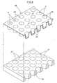
- Fig. 3 are explanatory views of a third embodiment of a
biochemical vessel relating to the present invention, (A) being a perspective
view showing an entire shape of the vessel, (B) being a partially enlarged
section,
- Fig. 4 are explanatory views of a fourth embodiment of a
biochemical vessel relating to the present invention, (A) being a perspective
view showing an entire shape of the vessel, (B) being a partially enlarged
section,
- Fig. 5 are explanatory views of a fifth embodiment of a biochemical
vessel relating to the present invention, (A) being a partially cutaway
perspective view showing an entire shape of the vessel, (B) being a partially
enlarged section,
- Fig. 6 are explanatory views of a sixth embodiment of a
biochemical vessel relating to the present invention, (A) being a partially
cutaway perspective view showing an entire shape of the vessel, (B) being a
partially enlarged section,
- Fig. 7 are explanatory views of a seventh embodiment of a
biochemical vessel relating to the present invention, (A) being a partially
cutaway perspective view showing an entire shape of the vessel, (B) being a
partially enlarged section,
- Fig. 8 is a perspective view illustrating a manufacturing method,
- Fig. 9 is a partially enlarged section illustrating a manufacturing
method of a biochemical vessel according to an eighth embodiment of the
invention, and
- Fig. 10 is a partially enlarged section illustrating a night
embodiment of a biochemical vessel relating to the present invention.
-
Best Mode of Embodying Invention
[First Embodiment]
-
Figs. 1(A) and (B) show an example of the first embodiment of the
present invention. Fig. 1 (A) is a perspective view showing an entire
biochemical vessel and Fig. 1 (B) is its partially enlarged section view.
-
As shown in Fig. 1, this biochemical vessel, as an example, is
formed by coating an outer side of a synthetic resin vessel body 10 with a
silicon dioxide film 11.
-
This synthetic resin vessel body 10 comprises a substantially
rectangular body as a whole consisting of a number of recesses 12 and wall
portions 13, the recesses 12 being provided as cylindrical portions disposed
side by side and extending along the vertical direction. And, as shown in
the figure, the many recesses 12 are partitioned from each other by the wall
portions 13.
-
And, the entire outer side of the synthetic resin vessel body 10
constructed as above is coated with the silicon dioxide film 11.
-
In this manner, this biochemical vessel includes many cells (s)
formed by coating the insides of the recesses 12 with the silicon dioxide film
11. In operation, by receiving a plurality of samples within the cells (s)
without being mixed with each other, e.g. various analyses or culture of
DNA can be carried out. Incidentally, in this embodiment, 8 x 12 = 96 cells
(s) are formed as an example.
-
Next, one exemplary manufacturing method of such biochemical
vessel as above will be briefly described.
-
First, the synthetic resin vessel body 10 is formed by a desired
method of any of synthetic resins having ultraviolet transparency, such as
polystyrene resin, into the shape dining the many recesses 12 side by side.
-
Next, the surface of the synthetic resin vessel body is modified by
UV irradiation treatment and then the silicon dioxide film is formed on its
outer side by a liquid phase method to be described next.
-
First, an SiO2 saturated aqueous solution in which
hydrosilicofluoric acid aqueous solution, hydrofluoric acid and silica gel are
at equilibrium as indicated by the following Formula (1) is prepared.
H2SiF6 + 2H2O 6HF + SiO2
-
Then, to this SiO2 saturated aqueous solution, a reaction
accelerator is added, thereby to obtain SiO2 supersaturated aqueous
solution. The reaction accelerator can be one capable of shifting the
equilibrium of the reaction of the above Formula (1) to the right side. For
instance, an accelerator which reacts with water or HF (e.g. aluminum, etc.)
can be employed. Incidentally, the reaction in the case of addition of
aluminum is indicated by the following Formula (2).
6HF + Al H3AlF6 + 3/2H2
-
Next, the synthetic resin vessel body is submerged in the SiO2
supersaturated aqueous solution for depositing the silicon dioxide (SiO2)
film on the surface of this synthetic resin vessel body. For instance, by
submerging it for 1 hour, coating of a silicon dioxide film of 200 nm can be
formed.
-
With such liquid phase method as described above, even when the
synthetic resin vessel body 10 has a complicated shape having a number of
recesses, a silicon dioxide film of a relatively uniform thickness can be
formed easily.
-
Incidentally, the silicon dioxide film of a predetermined thickness
should be formed advantageously by repeating a plurality of cycles of
submerging, rather than the film of the predetermined thickness is formed
at one time. For, this will effectively prevent penetration of an organic
solvent from a pinhole when an organic solvent is used as a sample.
-
Further, in case the biochemical vessel is employed for ultraviolet
spectrometry, in order to allow precision determination by avoiding
interference of the ultraviolet beam, it is preferred that the silicon dioxide
film have a thickness greater than 150 nm or smaller than 100 nm.
Further, the thickness smaller than 100 nm is more preferred since with
this, such film with uniform thickness in its entirety can be readily
obtained, so that determination with even higher precision is made
possible.
-
Incidentally, in this example, a great number of recesses 12 are
formed. However, the sole requirement is provision of a plurality of
recesses 12. Further, its shape is not limited to the cylindrical shape.
Instead, the recess can have any desired shape such as an angular column,
a cone, or a pyramid, etc. And, the silicon dioxide film 11 needs to coat at
least the inner faces of the recesses 12. Its forming method is not limited
to the liquid phase method described above. The method can also be CVD
method, PVD method, etc., of course.
[Second Embodiment]
-
Figs. 2 (A) and (B) show an example of the second embodiment of
the present invention. Fig. 2 (A) is a perspective view showing an entire
biochemical vessel and Fig. 2 (B) is its partially enlarged section view.
-
As shown in Fig. 2, this biochemical vessel is formed by attaching a
number of cylindrical members 23 erect on a rectangular glass substrate 21
via an inorganic adhesive 22. Many cells (s) are formed by spaces
delimited by the glass substrate 21 and the respective cylindrical members
23. In operation, by receiving a plurality of samples within the cells (s)
without being mixed with each other, e.g. various analyses or culture of
DNA can be carried out. Incidentally, in this embodiment, 8 x 12 = 96 cells
(s) are formed as an example.
-
The glass substrate 21 can be prepared by e.g. cutting open a
cylindrical UV transparent glass (PH160 from Phillips Inc.) and heating it
into a flat plate, then polishing the plate until it becomes transparent. In
this case, the glass advantageously obtains a very high transmission ratio
of 85% for ultraviolet ray of 230 nm to 300 nm. Incidentally, the glass
substrate 21 can be an UV transparent glass. For example, natural quartz
glass having a high UV transmission ratio of 80% or more, a synthetic
quartz glass, borosilicate glass can also be employed.
-
The cylindrical member 23 is formed into the cylindrical shape of
such inorganic material as various kinds of glass such as soda-lime glass,
various kinds of ceramics, various kinds of metal, etc.
-
And, the inorganic adhesive 22 is used for adhesive bonding of the
cylindrical members 23 to the glass substrate 21. If a low-melting-point
glass or a metal solder is employed, this will be advantageous because no
dissolution occurs even if an organic solvent is received in the cell (s).
-
Incidentally, in this case, as shown in Fig. 2 (A), as an example,
outer frames 24 formed of soda lime glass are fused to the outer periphery
of the glass substrate 21, whereby leak of samples to the outside can be
prevented advantageously.
[Third Embodiment]
-
Figs. 3 (A) and (B) show an example of the third embodiment of the
present invention. Fig. 3 (A) is a perspective view showing an entire
biochemical vessel and Fig. 3 (B) is its partially enlarged section view.
-
As shown in Fig. 3, this biochemical vessel is formed by bonding a
plate-like body 26 to the top of a rectangular glass substrate 21 by means of
the inorganic adhesive 22. The plate-like body 26 defines through holes 27
extending through the thickness thereof. Then, a number of cells (s) are
formed by spaces delimited by the respective through holes 27 and the glass
substrate 21. In operation, by receiving a plurality of samples within the
cells (s) without being mixed with each other, e.g. various analyses or
culture of DNA can be carried out.
-
The plate-like body 26 is formed of an inorganic material such as
various kinds of glass, e.g. soda lime glass, various kinds of ceramics,
various kinds of metal, etc, with defining the many through holes 27
extending through the thickness thereof. In this example, the plate-like
body 26 has substantially same planar dimensions as the glass substrate
21.
-
The rest of the construction is identical to the second embodiment.
[Fourth Embodiment]
-
Figs. 4 (A) and (B) show a modified example of the third
embodiment of the present invention. Fig. 4 (A) is a perspective view
showing an entire biochemical vessel and Fig. 4 (B) is its partially enlarged
section view.
-
As shown in Fig. 4, there is employed a plate-like body 26 defining
a number of through holes 27, each hole having a conical shape tapered
toward its lower side, i.e. having a progressively reduced diameter toward
the same. Then, the lower side of this plate-like body 26 is boned to the
top of a rectangular glass substrate 21 by means of the inorganic adhesive
22. A number of cells (s) having a progressively increased diameter toward
the upper side are formed by spaces delimited by the respective through
holes 27 of the plate-like body 26 and the glass substrate 21. Hence, the
inner faces of the cells (s) can be easily washed to be advantageous for
repeated use. Further, the plate-like body 26 defining the many through
holes 27 can be formed easily.
-
Incidentally, the material forming the plate-like body 26 should be
an inorganic material such as various kinds of glass, various kinds of
ceramics, various kinds of metal, just like the foregoing embodiments, if
solutions containing organic solvent are to be received in the cells (s).
Whereas, the material can be a synthetic resin, in the case of an ordinary
aqueous solution.
-
The rest of the construction is identical to the third embodiment.
[Fifth Embodiment]
-
Figs. 5 (A) and (B) show a modified example of the fourth
embodiment of the present invention. Fig. 5 (A) is a perspective view
showing an entire biochemical vessel and Fig. 5 (B) is its partially enlarged
section view.
-
As shown in Fig. 5, in this embodiment, in order to achieve weight
reduction of the biochemical vessel, for example the plate-like body 26
defines concave portions 32 so as to form hollow portions 33 in the plate-like
body 26 when the plate-like body 26 and the glass substrate 21 are bonded
to each other.
-
Incidentally, though not shown, in order to form the hollow
portions 33 in the glass substrate 21 when the plate-like body 26 and the
glass substrate 21 are bonded together, both the plate-like body 26 and the
glass substrate 21 may define the concave portions 32, so that the hollow
portions 33 may be formed in both the plate-like body 26 and the glass
substrate 21, even when the concave portions 32 are defined in the glass
substrate 21.
-
Further, the shape of the through hole 27 to be defined in the
plate-like body 26 is not limited to the one tapered toward the lower side,
but can be a cylindrical shape having a substantially same diameter over
its entire length.
-
The rest of the construction is identical to the third embodiment.
[Sixth Embodiment]
-
Figs. 6 (A) and (B) show an example of the sixth embodiment of the
present invention. Fig. 6 (A) is a perspective view showing an entire
biochemical vessel and Fig. 6 (B) is its partially enlarged section view.
-
As shown in Fig. 6, this biochemical vessel is constructed as an
ultraviolet transparent glass molded product 30 defining a number of holes
31 disposed side by side. These holes 31 correspond to the cells (s). In
operation, by receiving a plurality of samples within the cells (s) without
being mixed with each other, e.g. various analyses or culture of DNA can be
carried out. Incidentally, in this embodiment, 8 x 12 = 96 cells (s) are
formed as an example.
-
The ultraviolet transparent glass molded product 30 is formed by
rendering an ultraviolet transparent glass (e.g. natural quartz glass, a
synthetic quartz glass, borosilicate glass, etc.) into a melted condition or
softened condition and then forming this into the shape defining a number
of holes 31 disposed side by side by means of various types of molding
methods. Incidentally, as shown in the figure, if a bottom face 30a of this
ultraviolet transparent glass molded product 30 is formed into a smooth flat
surface by a polishing treatment, this will be advantageous for allowing
spectrometry to be effected with high precision when a visible beam, an
ultraviolet beam or an X-ray used in the spectrometry is caused to be
incident on that bottom face 30a along the vertical direction.
-
Further, in the hole 31, as shown in the figure, its bottom face 31a
is formed into a smooth flat surface by a polishing treatment. Hence,
spectrometry can be effected with high precision advantageously when a
visible beam, an ultraviolet beam or an X-ray used in the spectrometry is
caused to be incident on that bottom face 31a along the vertical direction.
-
Incidentally, if this hole 31 has a shape tapered from its opening
toward its bottom face as shown, this will be advantageous in that the
vessel can be washed easily to be used repeatedly and also the vessel can be
molded easily.
[Seventh Embodiment]
-
Figs. 7(A) and (B) show an example of the seventh embodiment of
the present invention. Fig. 7 (A) is a perspective view showing an entire
biochemical vessel and Fig. 7 (B) is its partially enlarged section view.
-
As shown in Fig. 7, in the case of this biochemical vessel, a
plate-like substrate 34 defines a plurality of through holes 27 extending
though the thickness thereof and then ultraviolet transparent glass
containers 35 are fitted into these respective through holes 27 and
peripheral wall-like outer peripheral faces of the glass containers 35 are
secured in a gapless manner to the inner peripheral faces of the through
holes 27. In operation, by receiving a plurality of samples within the cells
(s) formed by the glass containers 35 without being mixed with each other,
e.g. various analyses or culture of DNA can be carried out.
-
The plate-like substrate 34 is formed of an inorganic material such
as a resin material like polystyrene resin, various kinds of glass such as
soda lime glass, various kinds of ceramics, or various kinds of metal, into a
substantially rectangular shape as a whole, with small conical through
holes 27 tapered toward the lower side, i.e. having a progressively reduced
diameter toward the bottom face, being juxtaposed along the vertical and
lateral directions. And, within the respective through holes 27, there are
fixedly attached UV transparent glass containers 35. The glass container
35 is made of a glass having a high UV transmission ratio of 80% or higher,
such as natural quartz glass, synthetic quartz glass, borosilicate glass, etc.
and has a small conical shape tapered, i.e. having a progressively reduced
diameter, toward the bottom face side.
-
Referring to the manufacturing method of the biochemical vessel,
the heated and softened UV transparent glass is formed integrally into a
glass container molded product 36 having the many glass containers 35 in
one side thereof, as illustrated in Fig. 8 by e.g. a vacuum molding method.
Then, this glass container molded product 36 is placed over the plate-like
substrate 34 in such as manner as to fit the respective glass containers 35
into the respective through holes 27. Then, these are bonded to each other
by means of an inorganic or organic adhesive 22.
-
In this embodiment too, because the many cells (s) are formed with
increased diameter toward the upper face, the inner faces of the cells (s) can
be easily washed to be advantageous for repeated use.
[Eighth Embodiment]
-
Fig. 9 shows a modified embodiment of the seventh embodiment.
In this biochemical vessel, a plate-like substrate 34 is formed of an
inorganic material such as various kinds of ceramics, various kinds of metal,
etc. and has a rectangular shape as a whole. And, the substrate 34
defines a plurality of through holes 27 having conical shape tapered, i.e.
having a progressively reduced diameter, toward the bottom face side and
juxtaposed along the vertical and lateral directions. Then, over this
plate-like substrate 34, a heated and softened UV transparent glass plate
37 is placed in a gapless manner to be fitted into the respective through
holes 27 by e.g. the vacuum molding method. Then, the one side of the
plate-like substrate 34 and the inner peripheral faces of the through holes
27 are baked together, whereby the UV transparent glass containers 35
may be fitted into the respective through holes 27, with placing the outer
peripheral face of the glass container 35 in gapless contact with and fixed to
the inner peripheral face of the through hole 27.
-
The rest of the construction is identical to the sixth embodiment.
[Ninth Embodiment]
-
Fig. 10 shows a modified embodiment of the seventh embodiment
or eighth embodiment. In order to achieve weight reduction of the
biochemical vessel, the plate-like substrate 34 is formed of a thin plate
member and a through hole 27 is formed on the inner side of each
cylindrical wall portion 38.
-
The rest of the construction is identical to the sixth embodiment or
the seventh embodiment.
[Other Embodiments]
-
Next, other embodiments will be described.
- <1> In the foregoing embodiment, there have been described, by way of
one example, biochemical vessels having a number of cells (s) and all
configured as so-called plate type vessels. The invention is not limited
thereto. The outer shape of the vessel is not limited to the plate-type, as
long as the vessel defines a number of cells (s).
- <2> Further, the invention's biochemical vessels described so far have
flat bottom faces and flat bottoms of the cells (s). Hence, these are
advantageous for allowing precision determination especially when the
determination is made by e.g. a microplate reader for causing a
spectrometric visible beam, UV beam or X-ray to enter the bottom face of
the biochemical vessel along the vertical direction and then determining its
transmission beam.
Incidentally, UV spectrometry determinations were made
experimentally using a microplate reader, with varying the transmission
ratio for 230 nm to 300 mm beam to 58%, 65%, 70% and 75% by varying the
thickness from the bottom face of the biochemical vessel to the bottom of
each cell (s) to 2 mm, 1.7 mm, 1.5 mm and 1.3 mm, respectively. Then, it
was found that for precision determination, a transmission ratio of 70% or
higher is required.
- <3> Incidentally, the biochemical vessel according to the present
invention is capable of receiving within each cell (s) not only the organic
solvent, but also various kinds of liquid samples such as aqueous solution.
- <4> Further, in the detailed disclosure of the present invention, the
term, spectrometry, means any determination utilizing a transmission light
or a reflected light such as ultraviolet beam, visible beam, fluorescent beam,
X-ray beam, etc.
- <5> In the case of the biochemical vessel according to the ninth
embodiment of the present invention, a plurality of UV transparent glass
containers 35 formed separately from each other may be fitted within the
respective through holes 27, with the outer peripheral faces of the glass
containers 35 being fixed in a gapless manner to the inner peripheral faces
of the respective through holes 27 by means of adhesion.
-
Industrial Applicability
-
According to the present invention, it has become possible to
provide a biochemical vessel which has high organic solvent resistance and
which can be easily manufactured and allows the ultraviolet spectrometry.
The invention's biochemical vessel can be used advantageously as a
determination plate for a microplate reader for example.