EP1550822A1 - Verriegelungsvorrichtung für strömungskanalöffnungs-/-schliessgriff einer fluidsteuerung - Google Patents
Verriegelungsvorrichtung für strömungskanalöffnungs-/-schliessgriff einer fluidsteuerung Download PDFInfo
- Publication number
- EP1550822A1 EP1550822A1 EP03807960A EP03807960A EP1550822A1 EP 1550822 A1 EP1550822 A1 EP 1550822A1 EP 03807960 A EP03807960 A EP 03807960A EP 03807960 A EP03807960 A EP 03807960A EP 1550822 A1 EP1550822 A1 EP 1550822A1
- Authority
- EP
- European Patent Office
- Prior art keywords
- stopper
- handle
- support member
- lock device
- knob
- Prior art date
- Legal status (The legal status is an assumption and is not a legal conclusion. Google has not performed a legal analysis and makes no representation as to the accuracy of the status listed.)
- Withdrawn
Links
- 239000012530 fluid Substances 0.000 title claims abstract description 18
- 230000000452 restraining effect Effects 0.000 claims description 4
- 238000005452 bending Methods 0.000 description 4
- 238000004519 manufacturing process Methods 0.000 description 2
- 238000000034 method Methods 0.000 description 2
- 239000004065 semiconductor Substances 0.000 description 2
- 230000002411 adverse Effects 0.000 description 1
- 238000010276 construction Methods 0.000 description 1
- 238000009434 installation Methods 0.000 description 1
- 230000002265 prevention Effects 0.000 description 1
Images
Classifications
-
- F—MECHANICAL ENGINEERING; LIGHTING; HEATING; WEAPONS; BLASTING
- F16—ENGINEERING ELEMENTS AND UNITS; GENERAL MEASURES FOR PRODUCING AND MAINTAINING EFFECTIVE FUNCTIONING OF MACHINES OR INSTALLATIONS; THERMAL INSULATION IN GENERAL
- F16K—VALVES; TAPS; COCKS; ACTUATING-FLOATS; DEVICES FOR VENTING OR AERATING
- F16K35/00—Means to prevent accidental or unauthorised actuation
- F16K35/02—Means to prevent accidental or unauthorised actuation to be locked or disconnected by means of a pushing or pulling action
-
- F—MECHANICAL ENGINEERING; LIGHTING; HEATING; WEAPONS; BLASTING
- F16—ENGINEERING ELEMENTS AND UNITS; GENERAL MEASURES FOR PRODUCING AND MAINTAINING EFFECTIVE FUNCTIONING OF MACHINES OR INSTALLATIONS; THERMAL INSULATION IN GENERAL
- F16K—VALVES; TAPS; COCKS; ACTUATING-FLOATS; DEVICES FOR VENTING OR AERATING
- F16K35/00—Means to prevent accidental or unauthorised actuation
- F16K35/10—Means to prevent accidental or unauthorised actuation with locking caps or locking bars
-
- F—MECHANICAL ENGINEERING; LIGHTING; HEATING; WEAPONS; BLASTING
- F16—ENGINEERING ELEMENTS AND UNITS; GENERAL MEASURES FOR PRODUCING AND MAINTAINING EFFECTIVE FUNCTIONING OF MACHINES OR INSTALLATIONS; THERMAL INSULATION IN GENERAL
- F16K—VALVES; TAPS; COCKS; ACTUATING-FLOATS; DEVICES FOR VENTING OR AERATING
- F16K35/00—Means to prevent accidental or unauthorised actuation
- F16K35/06—Means to prevent accidental or unauthorised actuation using a removable actuating or locking member, e.g. a key
Definitions
- the present invention relates to a device for locking the channel opening-closing handle of fluid controllers, such as shutoff valves for use in semiconductor manufacturing apparatus, in its fully opening or fully closing position.
- JP-A No. 11-6581 discloses a lock device of the type mentioned for a channel opening-closing handle.
- the disclosed device comprises a stopper support member fixed to a fluid controller body, and a stopper supported by the support member and upwardly or downwardly movable between an upper position, i.e., locking position, for restraining a flat channel opening-closing handle by engagement therewith and a lower position, i.e., unlocking position, permitting the turn of the handle.
- the stopper comprises two members, and the device comprises many components and requires much time and labor for installation on the fluid controller.
- the lock device still remains to be improved.
- An object of the present invention is to provide a channel opening-closing handle lock device which comprises a stopper in the form of a single member and which is reduced in the number of components and easy to mount on fluid controllers.
- the present invention provides a lock device for a channel opening-closing handle of a fluid controller, the lock device comprising a stopper support member fixed to a controller body and a stopper supported by the support member and upwardly or downwardly movable between a locking position for restraining the handle having a flat knob by engagement with the handle and an unlocking position permitting the turn of the handle, the lock device being characterized in that the controller body has a rectangular parallelepipedal portion, a projecting cylinder provided on an upper wall of the parallelepipedal portion and having the handle removably attached to an upper end thereof, and a male screw portion provided around the cylinder, the support member having a rectangular plate provided with a circular through hole for the cylinder of the controller body to be fittingly inserted therethrough, a downward projection provided at lengthwise one end of the rectangular plate and held in contact with one side wall of the parallelepipedal portion of the controller body, and an extension extending outward from the plate beyond the parallelepipedal portion, the stopper being in the
- the support member extension is provided, for example, at the other end of the rectangular plate where the downward projection is not formed.
- the stopper inserting hole is formed in a corner of the extension. Preferably this hole is then positioned externally of the width of the handle knob when seen from above.
- the stopper contact portion is a side face of the vertical plate providing the stopper.
- the stopper extension can be provided alternatively at a portion of the rectangular plate which portion is orthogonal to the plate portion provided with the downward projection.
- the stopper restrains the handle from turning by engagement therewith. This eliminates the likelihood that the opening-closing handle will be shifted in position inadvertently, preventing such an accident that the fluid will not be passed through the controller properly to adversely affect the product to be obtained. Since a single plate provides the stopper, the lock device can be reduced in the number of components, while the stopper can be mounted on the controller body merely by fitting the stopper support member around the cylinder and tightening up a nut. Thus, the device can be mounted on the fluid controller easily, utilizing the construction of the controller advantageously.
- FIGS. 2 and 3 will be referred to as “left” and “right, “ respectively, and the lower side of FIG. 2 as “front,” and the upper side thereof as “rear.”
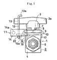
- FIGS. 1 to 3 show a fluid controller 1, and a channel opening-closing handle lock device 11 of the invention.
- the illustrated fluid controller 1 is a known two-way ball valve and comprises a controller body 2 and a channel opening-closing handle 3 having a flat knob 3a.
- the controller body 2 has a rectangular parallelepipedal portion 4 provided with an inlet pipe joint 5 and an outlet pipe joint 6, a projecting cylinder 7 provided on the top wall of the portion 4 and having the handle 3 attached to its upper end, and a tubular male screw portion 8 provided around the cylinder 7.
- the inlet pipe joint 5 projects leftward from the rectangular parallelepipedal portion 4, with the outlet pipe joint 6 projecting rightward from this portion 4.
- the knob 3a of the handle 3 has a generally rectangular shape when seen from above. When the channel is fully opened, the knob 3a is positioned in the left-right direction in alignment with both the inlet pipe joint 5 and the outlet pipe joint 6. When the handle 3 is turned clockwise from this position through 90 degrees as it is seen from above, the handle 3 is positioned to fully close the channel.
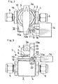
- the handle lock device 11 which is adapted to prevent the handle 3 in the fully closing position from turning toward an opening direction (counterclockwise direction when seen from above with the present embodiment), comprises a stopper support member 12 fixed to the controller body 2, a stopper 13 supported by the support member 12 and movable upward to an upper position in which the stopper 13 is in engagement with the handle 3 for the prevention of turn thereof, i.e., to a locking position, or downward to a lower position permitting the turn of the handle 3, i.e., to an unlocking position, and a lock 14 for which a key is held only by a person who can disengage the stopper 13.
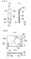
- the stopper support member 12 comprises a rectangular plate 15 having a circular through hole 16 for the cylinder 7 of the controller body 2 to be fittingly inserted therethrough, a downward projection 17 provided at lengthwise one end (i.e., the right end in the present embodiment) of the plate 15 and held in contact with one side wall (i.e., the rear side wall according to the embodiment) of the rectangular parallelepipedal portion 4 of the controller body 2, and an extension 15a extending outward from the plate 15 beyond the portion 4.
- the extension 15a of the support member 12 is provided at a corner thereof with a rectangular through hole 18 so as to be positioned externally of the width of the knob 3a of the handle 3 when seen from above.
- the downward projection 17 is formed, for example, by bending the lengthwise end portion of the plate 15, but may of course be formed alternatively by a method other than bending.
- the stopper support member 12 is secured to the rectangular parallelepipedal portion 4 of the controller body 2 with a nut 9 screwed on the male screw portion 8 of the controller body 2, with a holding ring 10 interposed between the nut 9 and the portion 4.
- the stopper 13 which is in the form of a rectangular plate, is upwardly or downwardly movably inserted through the rectangular hole 18 formed in the corner of the extension 15a of the support member 12.
- the stopper 13 is a vertically elongated rectangular plate and has a horizontal lug 13a projecting rearward from a top portion thereof which is positioned above the knob 3a of the handle 3.
- the horizontal lug 13a comes into contact with the upper surface of the stopper support member 12, restraining the stopper 13 from moving further downward.
- the portion of the stopper 13 slightly below the lug 13a serves as a contact portion 19 which comes into contact with the knob 3a of the handle 3 from outside widthwise of the knob 3a when the stopper 13 is in its locking position.
- a through hole 20 is formed in the stopper 13 at a portion thereof close to its lower end and positioned above the support member 12 when the stopper 13 is in the locking position, the hole 20 serving as a lock attaching portion.
- the stopper 13 has a through hole 21 having a small diameter and positioned below the hole 20. Unremovably fitted into the hole 21 is a pin 22 for preventing the stopper 13 from slipping off from support member 12 when the lock 14 is removed.
- the horizontal lug 13a of the stopper 13 is formed by bending an upper end portion of the rectangular plate, the lug may of course be formed by a method other than bending.
- the lock 14 is attached to the portion of the stopper 13 defining the lock attaching through hole 20 for preventing the stopper 13 from slipping off.
- a padlock is usable as the lock 14.
- a shackle 14a is inserted through the hole 20 and placed into a bore in the lock 14, whereby the stopper 13 is restrained from moving down. Further with the pin 22 preventing the stopper 13 from moving upward, the stopper 13 is held in the locking position while being prevented from turning. Consequently, it is impossible to turn the channel opening-closing handle 3 unless the lock 14 is removed using the key.
- the fluid controller 1 and the handle lock device 11 can be assembled by fitting the stopper support member 12 as positioned in a specified direction around the cylinder 7 of the controller body 2, securing the member 12 to the body 2 with the nut 9 and thereafter mounting the handle 3 in the fully closing position.
- the handle 3 can then be made lockable when in the fully closing position as mentioned above.
- the handle 3 can be made lockable in the fully open position.
- the knob 3a of the handle 3 has a generally rectangular shape when seen from above according to the embodiment described above, whereas a handle lock device can be provided similarly even if the handle knob 3a is shaped otherwise unless the knob has a completely cylindrical shape.
- the present invention can be embodied as a device for locking the channel opening-closing handle of fluid controllers, such as shutoff valves for use in semiconductor manufacturing apparatus, in its fully opening or closing position.
- the device provided comprises a stopper in the from of a single member and is reduced in the number of components and easy to mount on the controller.
Landscapes
- Engineering & Computer Science (AREA)
- General Engineering & Computer Science (AREA)
- Mechanical Engineering (AREA)
- Preventing Unauthorised Actuation Of Valves (AREA)
Applications Claiming Priority (3)
| Application Number | Priority Date | Filing Date | Title |
|---|---|---|---|
| JP2002297194A JP4264626B2 (ja) | 2002-10-10 | 2002-10-10 | 流体制御器の流路開閉ハンドルのロック装置 |
| JP2002297194 | 2002-10-10 | ||
| PCT/JP2003/010606 WO2004033946A1 (ja) | 2002-10-10 | 2003-08-22 | 流体制御器の流路開閉ハンドルのロック装置 |
Publications (1)
| Publication Number | Publication Date |
|---|---|
| EP1550822A1 true EP1550822A1 (de) | 2005-07-06 |
Family
ID=32089258
Family Applications (1)
| Application Number | Title | Priority Date | Filing Date |
|---|---|---|---|
| EP03807960A Withdrawn EP1550822A1 (de) | 2002-10-10 | 2003-08-22 | Verriegelungsvorrichtung für strömungskanalöffnungs-/-schliessgriff einer fluidsteuerung |
Country Status (8)
| Country | Link |
|---|---|
| US (1) | US20060145109A1 (de) |
| EP (1) | EP1550822A1 (de) |
| JP (1) | JP4264626B2 (de) |
| KR (1) | KR20050071537A (de) |
| CN (1) | CN1678859A (de) |
| AU (1) | AU2003254958A1 (de) |
| TW (1) | TW200413661A (de) |
| WO (1) | WO2004033946A1 (de) |
Families Citing this family (8)
| Publication number | Priority date | Publication date | Assignee | Title |
|---|---|---|---|---|
| KR100698163B1 (ko) * | 2006-01-17 | 2007-03-26 | 엘지전자 주식회사 | 방송 장르에 따른 신호처리장치를 갖는 이동통신단말기 |
| JP4727527B2 (ja) * | 2006-07-28 | 2011-07-20 | 日立建機株式会社 | 操作パターン選択弁のロック装置 |
| KR100828393B1 (ko) * | 2007-05-25 | 2008-05-08 | 태산이엔씨주식회사 | 밸브핸들용 안전캡 |
| EP2258971A1 (de) * | 2009-06-04 | 2010-12-08 | André Haake | Drehmomentstütze für eine Verriegelung |
| US9169943B2 (en) * | 2012-08-03 | 2015-10-27 | Brady Worldwide, Inc. | Valve lockout device |
| JP6128591B2 (ja) * | 2013-04-17 | 2017-05-17 | 株式会社フジキン | ロック装置及び弁装置 |
| JP2017172712A (ja) * | 2016-03-24 | 2017-09-28 | 株式会社栗本鐵工所 | バルブハンドル固定保持具 |
| JP7696147B1 (ja) * | 2025-04-10 | 2025-06-20 | 東フロコーポレーション株式会社 | ボールバルブの開閉ハンドル固定具 |
Family Cites Families (9)
| Publication number | Priority date | Publication date | Assignee | Title |
|---|---|---|---|---|
| US1689236A (en) * | 1925-12-14 | 1928-10-30 | Milwaukee Valve Co | Valve structure |
| US3532111A (en) * | 1969-03-10 | 1970-10-06 | Crane Co | Clamping device for valves |
| JPS5858171U (ja) * | 1981-10-16 | 1983-04-20 | 株式会社北沢バルブ | 施錠装置付バルブ |
| JPS6014071Y2 (ja) * | 1981-11-07 | 1985-05-04 | 株式会社浜井製作所 | ハンドル施錠式球弁 |
| US5360036A (en) * | 1992-08-24 | 1994-11-01 | Nibco, Inc. | Vented ball valve with lock-out ring |
| JP3091985B2 (ja) * | 1992-08-26 | 2000-09-25 | 日立バルブ株式会社 | バルブアクチュエータ |
| JP4217813B2 (ja) * | 1997-04-22 | 2009-02-04 | 株式会社フジキン | 流体制御器の流路開閉ハンドルのロック装置 |
| IL124146A (en) * | 1997-04-22 | 2001-08-08 | Fujikin Kk | Device for locking channel opening-closing handle of fluid controller |
| US6164318A (en) * | 1999-12-03 | 2000-12-26 | Dixon; Kenneth | Valve locking system |
-
2002
- 2002-10-10 JP JP2002297194A patent/JP4264626B2/ja not_active Expired - Fee Related
-
2003
- 2003-08-22 EP EP03807960A patent/EP1550822A1/de not_active Withdrawn
- 2003-08-22 KR KR1020057005731A patent/KR20050071537A/ko not_active Withdrawn
- 2003-08-22 WO PCT/JP2003/010606 patent/WO2004033946A1/ja not_active Ceased
- 2003-08-22 CN CNA03820116XA patent/CN1678859A/zh active Pending
- 2003-08-22 US US10/530,697 patent/US20060145109A1/en not_active Abandoned
- 2003-08-22 AU AU2003254958A patent/AU2003254958A1/en not_active Abandoned
- 2003-10-09 TW TW092128037A patent/TW200413661A/zh unknown
Non-Patent Citations (1)
| Title |
|---|
| See references of WO2004033946A1 * |
Also Published As
| Publication number | Publication date |
|---|---|
| US20060145109A1 (en) | 2006-07-06 |
| KR20050071537A (ko) | 2005-07-07 |
| CN1678859A (zh) | 2005-10-05 |
| TW200413661A (en) | 2004-08-01 |
| JP4264626B2 (ja) | 2009-05-20 |
| WO2004033946A1 (ja) | 2004-04-22 |
| AU2003254958A1 (en) | 2004-05-04 |
| JP2004132456A (ja) | 2004-04-30 |
Similar Documents
| Publication | Publication Date | Title |
|---|---|---|
| CA2235273C (en) | Device for locking channel opening-closing handle of fluid controller | |
| US6959909B2 (en) | Actuating handle assembly | |
| CA2926337C (en) | Valve handle lock | |
| EP1550822A1 (de) | Verriegelungsvorrichtung für strömungskanalöffnungs-/-schliessgriff einer fluidsteuerung | |
| JP4902610B2 (ja) | 止水栓装置及びこれを用いた給水設備 | |
| US8418515B2 (en) | Valve operated by a master key | |
| US6718804B1 (en) | Valve lockout device | |
| KR20150034830A (ko) | 로킹장치가 구비된 앵글밸브 | |
| US7114698B2 (en) | Quarter turn valve locking device | |
| US20190293109A1 (en) | Lockout device and a method for its use | |
| JP3234555B2 (ja) | ハンドルロック装置 | |
| EP1873433A1 (de) | Flüssigkeitskontrollvorrichtung | |
| US7216667B2 (en) | Valve opening/closing handle lock mechanism | |
| KR100607601B1 (ko) | 잠금장치가 구비된 밸브 | |
| EP1074772B1 (de) | Kugelventil mit schlüsselbetätigtes Schloss | |
| KR101050637B1 (ko) | 실제 배출유량률 표시형 볼밸브 | |
| US20190024353A1 (en) | A device for resisting rotation of a tap | |
| KR102868493B1 (ko) | 안전레버가 구비된 밸브 | |
| US20050167628A1 (en) | Reversible ball valve handle | |
| CA2560793A1 (en) | Apparatus for controlling flow through a conduit | |
| IL136218A (en) | Device for locking channel opening-closing handle of fluid controller | |
| JP4217813B2 (ja) | 流体制御器の流路開閉ハンドルのロック装置 | |
| KR200287181Y1 (ko) | 가스밸브용 잠금장치 | |
| KR200145997Y1 (ko) | 각종 밸브 및 전동밸브 잠금장치 | |
| WO2007105966A1 (en) | Plumbing fitting |
Legal Events
| Date | Code | Title | Description |
|---|---|---|---|
| PUAI | Public reference made under article 153(3) epc to a published international application that has entered the european phase |
Free format text: ORIGINAL CODE: 0009012 |
|
| 17P | Request for examination filed |
Effective date: 20050412 |
|
| AK | Designated contracting states |
Kind code of ref document: A1 Designated state(s): AT BE BG CH CY CZ DE DK EE ES FI FR GB GR HU IE IT LI LU MC NL PT RO SE SI SK TR |
|
| AX | Request for extension of the european patent |
Extension state: AL LT LV MK |
|
| DAX | Request for extension of the european patent (deleted) | ||
| RBV | Designated contracting states (corrected) |
Designated state(s): CH DE FR GB IT LI NL |
|
| STAA | Information on the status of an ep patent application or granted ep patent |
Free format text: STATUS: THE APPLICATION IS DEEMED TO BE WITHDRAWN |
|
| 18D | Application deemed to be withdrawn |
Effective date: 20080301 |