US6959909B2 - Actuating handle assembly - Google Patents
Actuating handle assembly Download PDFInfo
- Publication number
- US6959909B2 US6959909B2 US10/764,616 US76461604A US6959909B2 US 6959909 B2 US6959909 B2 US 6959909B2 US 76461604 A US76461604 A US 76461604A US 6959909 B2 US6959909 B2 US 6959909B2
- Authority
- US
- United States
- Prior art keywords
- head
- handle assembly
- slot
- engageable
- shaft
- Prior art date
- Legal status (The legal status is an assumption and is not a legal conclusion. Google has not performed a legal analysis and makes no representation as to the accuracy of the status listed.)
- Expired - Fee Related, expires
Links
- 230000006835 compression Effects 0.000 claims description 12
- 238000007906 compression Methods 0.000 claims description 12
- 238000003780 insertion Methods 0.000 claims description 3
- 230000037431 insertion Effects 0.000 claims description 3
- 230000000717 retained effect Effects 0.000 abstract 1
- 239000012530 fluid Substances 0.000 description 5
- 238000004519 manufacturing process Methods 0.000 description 4
- 230000000712 assembly Effects 0.000 description 3
- 238000000429 assembly Methods 0.000 description 3
- 238000000034 method Methods 0.000 description 3
- 230000008569 process Effects 0.000 description 2
- 230000009471 action Effects 0.000 description 1
- 238000012824 chemical production Methods 0.000 description 1
- 230000001066 destructive effect Effects 0.000 description 1
- 238000005553 drilling Methods 0.000 description 1
- 238000009434 installation Methods 0.000 description 1
- 230000003993 interaction Effects 0.000 description 1
- 238000012423 maintenance Methods 0.000 description 1
- 238000005065 mining Methods 0.000 description 1
- 238000005504 petroleum refining Methods 0.000 description 1
- 238000004080 punching Methods 0.000 description 1
- 230000008439 repair process Effects 0.000 description 1
- 230000000007 visual effect Effects 0.000 description 1
- 238000004065 wastewater treatment Methods 0.000 description 1
Images


Classifications
-
- F—MECHANICAL ENGINEERING; LIGHTING; HEATING; WEAPONS; BLASTING
- F16—ENGINEERING ELEMENTS AND UNITS; GENERAL MEASURES FOR PRODUCING AND MAINTAINING EFFECTIVE FUNCTIONING OF MACHINES OR INSTALLATIONS; THERMAL INSULATION IN GENERAL
- F16K—VALVES; TAPS; COCKS; ACTUATING-FLOATS; DEVICES FOR VENTING OR AERATING
- F16K35/00—Means to prevent accidental or unauthorised actuation
- F16K35/02—Means to prevent accidental or unauthorised actuation to be locked or disconnected by means of a pushing or pulling action
- F16K35/022—Means to prevent accidental or unauthorised actuation to be locked or disconnected by means of a pushing or pulling action the locking mechanism being actuated by a separate actuating element
- F16K35/025—Means to prevent accidental or unauthorised actuation to be locked or disconnected by means of a pushing or pulling action the locking mechanism being actuated by a separate actuating element said actuating element being operated manually (e.g. a push-button located in the valve actuator)
-
- F—MECHANICAL ENGINEERING; LIGHTING; HEATING; WEAPONS; BLASTING
- F16—ENGINEERING ELEMENTS AND UNITS; GENERAL MEASURES FOR PRODUCING AND MAINTAINING EFFECTIVE FUNCTIONING OF MACHINES OR INSTALLATIONS; THERMAL INSULATION IN GENERAL
- F16K—VALVES; TAPS; COCKS; ACTUATING-FLOATS; DEVICES FOR VENTING OR AERATING
- F16K31/00—Actuating devices; Operating means; Releasing devices
- F16K31/44—Mechanical actuating means
- F16K31/60—Handles
- F16K31/602—Pivoting levers, e.g. single-sided
-
- F—MECHANICAL ENGINEERING; LIGHTING; HEATING; WEAPONS; BLASTING
- F16—ENGINEERING ELEMENTS AND UNITS; GENERAL MEASURES FOR PRODUCING AND MAINTAINING EFFECTIVE FUNCTIONING OF MACHINES OR INSTALLATIONS; THERMAL INSULATION IN GENERAL
- F16K—VALVES; TAPS; COCKS; ACTUATING-FLOATS; DEVICES FOR VENTING OR AERATING
- F16K35/00—Means to prevent accidental or unauthorised actuation
- F16K35/06—Means to prevent accidental or unauthorised actuation using a removable actuating or locking member, e.g. a key
-
- Y—GENERAL TAGGING OF NEW TECHNOLOGICAL DEVELOPMENTS; GENERAL TAGGING OF CROSS-SECTIONAL TECHNOLOGIES SPANNING OVER SEVERAL SECTIONS OF THE IPC; TECHNICAL SUBJECTS COVERED BY FORMER USPC CROSS-REFERENCE ART COLLECTIONS [XRACs] AND DIGESTS
- Y10—TECHNICAL SUBJECTS COVERED BY FORMER USPC
- Y10T—TECHNICAL SUBJECTS COVERED BY FORMER US CLASSIFICATION
- Y10T137/00—Fluid handling
- Y10T137/7069—With lock or seal
- Y10T137/7256—Locks against rotary motion
Definitions
- This invention concerns handle assemblies for use with manually actuatable devices, such as valves.
- valves for fluid control are often actuated and adjusted manually in industrial installations in the course of operation of various industrial processes such as petroleum refining, paper manufacture, mining, chemical production and waste water treatment plants to cite but a few examples.
- Manual adjustment of valves allows the industrial processes controlled by the fluid flow through the valves to be optimized for various factors such as product yield, throughput, reaction rate, as well as other parameters associated with the economics and efficiency of the processes.
- valves also include the ability to lock the valve in the closed or open positions. Locking the valve in the closed position will help prevent mishaps during system maintenance, when portions of the system may be disassembled for replacement or repair. Locking the valve in the open position will help ensure that fluid flow is not halted inadvertently during operation. It is also advantageous to have the valve be tamper resistant to prevent unauthorized opening of the valve and thereby prevent theft of the product flowing through the system.
- the aforementioned refinements for devices such as valves may be effected using handle assemblies as described and claimed below.
- the invention concerns a handle assembly engageable with a shaft extending from a device, such as a valve, for rotating the shaft to actuate the device.
- the handle assembly comprises a head having a receptacle therein sized to receive the shaft.
- the shaft rotates with the head.
- An elongated grip is attached to the head and projects outwardly therefrom. The grip facilitates manual rotation of the head when the handle assembly is mounted on the device.
- An arcuate slot is positioned in the head and has a concave side facing the receptacle.
- the slot preferably has first and second ends disposed opposite to one another.
- a limit post is fixedly attachable to the device and projects into the slot.
- the limit post is engageable with at least one of the first and second ends of the slot to limit rotation of the head relatively to the device.
- a stop body is positioned within the slot and movable along it to a predetermined position between its first and second ends.
- the stop body has first and second gripping surfaces positioned on opposite sides of the head. The gripping surfaces are engageable with the head, at least one of the gripping surfaces is movable into and out of engagement with the head for compressing the head between the gripping surfaces and thereby temporarily fixing the stop body at the predetermined position.
- the stop body is engageable with the limit post upon rotation of the head to limit rotation of the head.
- the handle assembly may also include a hold fast body for temporarily preventing rotation of the head and thereby fix it and the shaft in a predetermined position relatively to the device.
- the hold fast body is fixedly attachable to the device and has a compression member positioned adjacent to the head. The compression member is movable into and out of engagement with the head to compress it and temporarily fix the head in the predetermined position.
- the invention also concerns another embodiment of a handle assembly engageable with a shaft extending from a device such as a valve, the handle assembly for rotating the shaft to actuate the device.
- the handle assembly is engageable with a lock for preventing rotation of the shaft.
- the handle assembly comprises a head having a receptacle therein sized to receive the shaft, the shaft rotating with the head.
- a first aperture extends through the head.
- a plate is fixedly mountable on the device and positionable between the head and the device.
- the plate has a second aperture extending therethrough.
- the first and second apertures are alignable with one another for receiving the lock therethrough upon rotation of the head.
- the lock prevents rotation of the head relatively to the plate when it is engaged with the apertures.
- An elongated grip is attached to the head. The grip projects outwardly therefrom and facilitates manual rotation of the head when the handle assembly is mounted on the device.
- the plate may be attached to the device using a non-removable fastener to make the device tamper resistant.
- a blind hole extends through the head and intersects the receptacle.
- a pin is insertable within the blind hole and is engageable with the shaft for retaining the head to the shaft.
- the head is substantially non-removable from the shaft upon insertion of the pin into the blind hole and engagement with the shaft, thus, further preventing unauthorized actuation of the device by removing the handle assembly.
- FIG. 1 is a perspective view of a handle assembly mounted on a device, the device shown in phantom line;
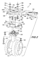
- FIG. 2 is an exploded perspective view of the handle assembly shown in FIG. 1 ;
- FIGS. 3A and 3B are sectional plan views taken at line 3 A— 3 A of FIG. 1 ;
- FIGS. 4A and 4B are sectional side views taken at line 4 A— 4 A of FIG. 3A ;
- FIG. 5 is a perspective view of another embodiment of a handle assembly mounted on a device, the device shown in phantom line;
- FIG. 6 is an exploded perspective view of the handle assembly shown in FIG. 5 ;
- FIG. 7 is a sectional plan view take at line 7 — 7 of FIG. 5 ;
- FIG. 8 is a sectional side view taken at line 8 — 8 of FIG. 7 .
- FIG. 1 shows a handle assembly 10 mounted on a device, such as a valve 12 , the valve being shown by way of example only and not intended to limit the use of the handle assembly to a particular application, the handle assembly 10 being adaptable for use with virtually any device that is manually actuated.
- a device such as a valve 12
- the valve being shown by way of example only and not intended to limit the use of the handle assembly to a particular application, the handle assembly 10 being adaptable for use with virtually any device that is manually actuated.
- valve 12 comprises a valve body 14 , a valve closure member 16 rotatably mounted within the valve body and a shaft 18 attached to the closure member 16 and extending outwardly from the valve body 14 .
- Rotation of the shaft 18 moves the valve closure member 16 between an open and a closed position to control fluid flow through the line in which the valve 12 is installed.
- Shaft 18 is surrounded by a flange 20 having various mounting holes 22 that receive fasteners for mounting various actuators on the valve 12 , such as the handle assembly 10 .
- Handle assembly 10 includes a head 24 having a receptacle 26 sized and shaped to receive shaft 18 .
- the head 24 and the shaft 18 rotate together by virtue of the engagement of the shaft and the receptacle 26 in the head.
- An elongated grip 28 is attached to head 24 , the grip projecting outwardly from the head to facilitate manual turning of the head to open and closed valve 12 .
- Handle assembly 10 may include a plate 30 mounted beneath head 24 on flange 20 and secured thereto by bolts and nuts 32 engaging holes 22 .
- Plate 30 has indexing projections 31 positioned in spaced apart relation opposite to one another for engagement with flange 20 .
- the indexing projections 31 are preferably formed by punching the projection outwardly from the plate 30 in a stamping operation.
- the projections 31 are in spaced relation to one another such that they engage the sides of flange 20 when the plate 30 is properly oriented relatively to the valve 12 , the flange 20 being sized differently in its cross- sectional dimensions to receive the indexing projections 31 when plate 30 is properly oriented, the projections 31 riding on the upper surface of the flange 20 and preventing proper engagement of the plate 30 with the flange 20 otherwise.
- Proper positioning of the plate 30 on flange 20 ensures that when the valve 12 is open, the grip 28 aligns with the pipe in which the valve is located, thereby providing a visual indication of whether the valve is open or closed, as is customary.
- Plate 30 has a plurality of teeth 34 extending outwardly away from receptacle 26 along an arcuate path 36 that matches the arcuate motion of the handle assembly 10 when turned.
- an elongated latch 38 is mounted on the grip 28 .
- latch 38 has a first end portion 40 engageable with teeth 34 , and a second end portion 42 that extends lengthwise along grip 28 .
- engagement of first end portion 40 with teeth 34 allows the grip 28 and head 24 to be temporarily set at any one of a plurality of angles 44 established by the teeth 34 , the teeth providing an index for positioning the valve closure member (see FIG. 2 ) at any one of a plurality of discrete positions and thereby controlling the degree to which the valve is opened or closed.
- the latch 38 is mounted on grip 28 and pivots about axis 46 as indicated by arrows 48 . Pivoting motion of the latch is effected manually by applying an upward force to the second end portion 42 . This action disengages the first end portion 40 of the latch 38 from teeth 34 and allows the grip 28 and head 24 to be rotated through an arcuate path 50 (see FIG. 3B ) to any one of a plurality of discrete positions determined by the interaction of the first end 40 of latch 38 with the teeth 34 . As best shown in FIGS. 4A and 4B , latch 38 is biased by a compression spring 52 acting between grip 28 and the second end portion 42 of the latch to normally keep the first end portion 40 in engagement with teeth 34 . Other embodiments may use tension springs for biasing, as well as other types of biasing devices.
- plate 30 and head 24 cooperate to allow the handle assembly 10 to be locked in a desired position, for example, in the fully opened or fully closed position.
- Plate 30 has apertures 54 and 56 that are alignable one at a time with an aperture 58 extending through the head 24 .
- the plate aperture 54 is positioned so that it aligns with head aperture 58 when the valve closure member 16 is in the fully opened position as shown in FIG. 1 . Alignment of the apertures 54 and 58 permits them to receive a lock 60 , shown in phantom line, that prevents movement of the head 24 relative to the valve 12 .
- head aperture 58 aligns with plate aperture 56 (see FIG. 3B ) and the aligned apertures 58 and 56 may receive lock 60 for locking the valve 12 in the closed position.
- Handle assembly 10 also has features that allow infinite adjustment positioning of the position of closure member 16 . Infinite adjustment positioning is effected via a hold fast body 62 , shown in FIG. 1 .
- hold fast body 62 comprises a threaded limit post 64 that is fixedly attached to flange 20 and extends upwardly through an arcuately shaped slot 66 in head 24 .
- a concave side 68 of slot 66 faces the receptacle 26 , and the curvature of the slot 66 matches the path of motion of the head 24 when it is rotated to rotate the shaft 18 . This allows the head 24 to turn relatively to the limit post 64 without interference.
- a compression member preferably in the form of a jam nut 70 , is positioned on the limit post 64 adjacent to the head 24 .
- Jam nut 70 may be tightened to compressively engaged the head 24 and temporarily fix the head in a desired predetermined position relatively to valve 12 corresponding to the desired degree of valve opening or closing.
- Engagement of the jam nut 70 with head 24 is preferably effected through a locking washer 72 and a flat washer 74 .
- the locking washer 72 prevents the jam nut 70 from loosening inadvertently under vibration, and the flat washer 74 acts as a sacrificial surface to prevent gouging of the head 24 .
- Limit post 64 also provides a positive stop when it engages the ends 66 a and 66 b of slot 66 to confine the motion of the valve closure member between the open and closed positions.
- Stop body 76 acts as a memory stop that allows the head 24 to be rotated to the same predetermined position each time it is actuated.
- the stop body 76 is positioned within slot 66 and comprises a threaded bolt 78 extending through the slot 66 , and a nut 80 retaining the bolt 78 within the slot.
- the bolt 78 may be moved to a desired position along the slot 66 between the ends 66 a and 66 b , and fixed in that position by tightening the nut 80 .
- the head 82 of bolt 78 and the nut 80 act as gripping surfaces positioned on opposite sides of the head 24 .
- the nut 80 When the nut 80 is tightened, it temporarily fixes the bolt 78 in the desired position between the ends 66 a and 66 b of slot 66 .
- the stop body 76 engages the limit post 64 , preventing further motion of the head 24 , positioning the head 24 and, consequently, the valve closure member 16 , in a desired position. Gripping between the nut 80 and the head 24 is preferably effected through a locking washer 84 and a flat washer 86 .
- the locking washer 84 prevents the nut 80 from loosening inadvertently under vibration, and the flat washer 86 acts as a sacrificial surface to prevent gouging of the head 24 .
- FIGS. 5 and 6 illustrate a tamper resistant handle assembly 88 .
- the tamper resistant embodiment 88 has plate apertures 54 and 56 that can be aligned with head aperture 58 and receive a lock 60 to secure the head 24 in one of two positions.
- the valve 12 could be easily opened by removing jam nut 70 and lifting the head 24 off of the shaft 18 by sliding head aperture 58 along the lock's shackle 90 . This would expose shaft 18 which can then be turned using a wrench to open the valve 12 .
- non-removable fasteners 92 to attach the plate 30 to the valve 12 as shown in FIG. 6 .
- non-removable and tamper resistant refer to fasteners that, once installed, may not be readily or easily removed by tools commonly available, removal of such fasteners requiring destructive methods such as sawing or drilling.
- the preferred type of non-removable fasteners 92 have breakaway head portions 98 on both the bolt 92 a and the nut 92 b .
- the breakaway head portions 98 are shaped to allow sufficient torque to be applied to the nut 92 b and bolt 92 a by means of a tool such as wrench 100 to secure the fastener 92 to the valve.
- the head portions 98 are attached to the nut 92 b and the bolt 92 a by a neck 102 having a reduced cross-sectional area which fails upon the application of a predetermined torque greater than is needed to secure the nut to the bolt. As shown in FIG.
- failure of the neck 102 allows removal of the head portions 98 , leaving only smooth retainer portions 104 on the bolt 92 a and the nut 92 b that do not provide any purchase for tools such as wrenches or pliers, making it very difficult to remove plate 30 using common hand tools.
- Other examples of tamper resistant/non-removable fasteners include “one-way screws” wherein the slot is deformed so that the screw may only be turned in one direction, as well as fasteners having heads that receive special tools not commonly available.
- Handle assemblies according to the invention provide numerous advantages for actuating valves and other devices.
- the advantages include the capability to temporarily fix the valve closure member in a desired position, to open the valve repeatedly to a predetermined position, to lock the valve in either the closed or open position and to render the valve tamper resistant to common hand tools.
Landscapes
- Engineering & Computer Science (AREA)
- General Engineering & Computer Science (AREA)
- Mechanical Engineering (AREA)
- Preventing Unauthorised Actuation Of Valves (AREA)
Abstract
Description
Claims (17)
Priority Applications (1)
| Application Number | Priority Date | Filing Date | Title |
|---|---|---|---|
| US10/764,616 US6959909B2 (en) | 2004-01-26 | 2004-01-26 | Actuating handle assembly |
Applications Claiming Priority (1)
| Application Number | Priority Date | Filing Date | Title |
|---|---|---|---|
| US10/764,616 US6959909B2 (en) | 2004-01-26 | 2004-01-26 | Actuating handle assembly |
Publications (2)
| Publication Number | Publication Date |
|---|---|
| US20050161624A1 US20050161624A1 (en) | 2005-07-28 |
| US6959909B2 true US6959909B2 (en) | 2005-11-01 |
Family
ID=34795304
Family Applications (1)
| Application Number | Title | Priority Date | Filing Date |
|---|---|---|---|
| US10/764,616 Expired - Fee Related US6959909B2 (en) | 2004-01-26 | 2004-01-26 | Actuating handle assembly |
Country Status (1)
| Country | Link |
|---|---|
| US (1) | US6959909B2 (en) |
Cited By (36)
| Publication number | Priority date | Publication date | Assignee | Title |
|---|---|---|---|---|
| US20060000996A1 (en) * | 2004-07-02 | 2006-01-05 | Giovanni Soldo | Handling device associable to an on-off valve for a fluid in a duct |
| US20060199525A1 (en) * | 2005-01-11 | 2006-09-07 | Venmar Ventilation Inc | Adjustable damper assembly |
| US20080061261A1 (en) * | 2006-09-12 | 2008-03-13 | Victaulic Company | Slow closing actuator and valve |
| US20090045362A1 (en) * | 2007-04-20 | 2009-02-19 | Michna Ii Michael | Positive Locking Valve Control Device With Squeeze Trigger |
| US20090057584A1 (en) * | 2007-08-29 | 2009-03-05 | Strahman Valves, Inc. | Lockable Sampling Valve |
| US20090152484A1 (en) * | 2007-12-14 | 2009-06-18 | Leblanc Ronald | Tamper-proof valve locking device |
| US20090229682A1 (en) * | 2008-03-17 | 2009-09-17 | Honeywell International Inc. | Regulator valve with locking system |
| US20090261280A1 (en) * | 2006-03-20 | 2009-10-22 | Hiroyuki Matsushita | Rotary Valve |
| US20100243930A1 (en) * | 2009-03-30 | 2010-09-30 | Long Ross E | Manual valve operators having a lockout device |
| US7849877B2 (en) | 2007-03-01 | 2010-12-14 | Zodiac Pool Systems, Inc. | Diverter valve |
| US20120193558A1 (en) * | 2011-02-01 | 2012-08-02 | Hoots Joshua Lee | Valve Switchbox |
| USD678471S1 (en) * | 2011-01-13 | 2013-03-19 | Bulk Tank, Inc. | Valve with handle extension |
| USD678473S1 (en) * | 2011-01-13 | 2013-03-19 | Bulk Tank, Inc. | Handle extension for valve |
| USD678472S1 (en) * | 2011-01-13 | 2013-03-19 | Bulk Tank Inc | Valve handle |
| US8402798B2 (en) | 2008-04-28 | 2013-03-26 | Master Lock Company Llc | Locking clamp |
| US20130187072A1 (en) * | 2012-01-24 | 2013-07-25 | Lavelle Industries, Inc. | Flow adjuster and key combination |
| USD699326S1 (en) | 2012-08-03 | 2014-02-11 | Brady Worldwide, Inc. | Valve lockout device |
| US8662108B2 (en) * | 2011-02-18 | 2014-03-04 | Eaton Corporation | Quick connect fluid coupling |
| WO2014035781A1 (en) * | 2012-08-30 | 2014-03-06 | Master Lock Company Llc | Lockout device |
| US8806906B1 (en) * | 2011-12-29 | 2014-08-19 | Bryce M. Bagby | Actuator lock-out bracket |
| USD711509S1 (en) * | 2012-12-26 | 2014-08-19 | Bulk Tank Inc. | Aeration butterfly valve |
| DE202014105683U1 (en) | 2014-11-25 | 2014-12-08 | Jdv Control Valves Co., Ltd. | Valve shaft handle and fluid valve with handle |
| CN104613226A (en) * | 2015-02-09 | 2015-05-13 | 胡俊 | Ceramic filter flow-limiting valve gate |
| US20150300504A1 (en) * | 2012-11-30 | 2015-10-22 | Shanghai Hongyan Returnable Transit Packagings Co. Ltd. | Valve with a hinged valve core |
| US9169943B2 (en) | 2012-08-03 | 2015-10-27 | Brady Worldwide, Inc. | Valve lockout device |
| US9217514B1 (en) | 2011-12-29 | 2015-12-22 | Bryce M. Bagby | Actuator lock-out bracket |
| US9267613B2 (en) | 2012-08-03 | 2016-02-23 | Brady Worldwide, Inc. | Valve lockout device |
| WO2017087352A1 (en) * | 2015-11-16 | 2017-05-26 | Hayward Industries, Inc. | Ball valve |
| US10203703B2 (en) | 2014-03-04 | 2019-02-12 | Mi Valve, Llc | Airflow balancing valve for HVAC systems |
| USD845441S1 (en) * | 2016-04-01 | 2019-04-09 | Jeffrey Allen Bertrem | Directional control valve locking device |
| USD880658S1 (en) * | 2018-06-29 | 2020-04-07 | Emkade Distribution, Inc. | Valve handle |
| USD886241S1 (en) * | 2018-02-16 | 2020-06-02 | Asahi Yukizai Corporation | Valve handle |
| US10955065B2 (en) | 2019-02-28 | 2021-03-23 | Iron Horse Industries, Llc | Locking apparatus for a rotating valve actuator |
| US20230341059A1 (en) * | 2022-04-21 | 2023-10-26 | Carrier Corporation | Selector and lockout valve mistake-proof design features |
| US12292126B2 (en) * | 2023-06-07 | 2025-05-06 | Scott Wu | Inflator valve connector |
| US12523304B1 (en) | 2024-10-11 | 2026-01-13 | The Metraflex Company | Butterfly valve |
Families Citing this family (11)
| Publication number | Priority date | Publication date | Assignee | Title |
|---|---|---|---|---|
| DE502005006430D1 (en) * | 2005-09-20 | 2009-02-26 | Fischer Georg Rohrleitung | Valve with handle |
| CN102906478A (en) * | 2010-04-08 | 2013-01-30 | 阿尔特拉弗洛股份有限公司 | Valve with notch plate having enhanced strength |
| JP5898577B2 (en) * | 2012-06-25 | 2016-04-06 | Ckd株式会社 | Fluid control unit, fluid control integrated unit |
| ES2656025T3 (en) * | 2013-08-12 | 2018-02-22 | Aeris Soluciones De Control, S.L. | Valve that has an opening or closing limiting device |
| USD746948S1 (en) | 2014-02-24 | 2016-01-05 | Ultraflo Corporation | Valve |
| US10155681B1 (en) * | 2018-07-19 | 2018-12-18 | Robert J. Gordhamer | Water treatment systems and methods |
| CN109458485B (en) * | 2018-12-27 | 2024-01-12 | 宁波东灵水暖空调配件有限公司 | Connection structure of main shaft and valve plate shaft of valve actuating mechanism |
| CN110081232B (en) * | 2019-04-28 | 2020-06-19 | 南漳县庆瑞精密铸造有限公司 | Air volume regulating valve switch handle for roasting furnace |
| CN114060546B (en) * | 2021-11-16 | 2023-08-29 | 天津卡尔斯阀门股份有限公司 | Gate valve capable of being opened and closed rapidly in inner cavity in swinging mode |
| CN115990575A (en) * | 2023-02-15 | 2023-04-21 | 三一重型装备有限公司 | A vibrating screen with adjustable fineness modulus and its adjustment method |
| IT202300021141A1 (en) * | 2023-10-11 | 2025-04-11 | Riv Rubinetterie Italiane Velatta S P A | VALVE |
Citations (21)
| Publication number | Priority date | Publication date | Assignee | Title |
|---|---|---|---|---|
| US2994503A (en) | 1958-09-29 | 1961-08-01 | Mueller Co | Rotary plug valve |
| US3384339A (en) | 1965-09-10 | 1968-05-21 | William E. Cornell | Tamperproof valve handle |
| US3722853A (en) | 1971-12-08 | 1973-03-27 | Eclipse Fuel Eng Co | Pilfer proof valve |
| US3744752A (en) | 1971-11-17 | 1973-07-10 | Parker & Harper Mfg Co | Detachable handle for control devices |
| US3807254A (en) * | 1972-11-20 | 1974-04-30 | Robertshaw Controls Co | Control device having an adjustable range and method of making the same |
| US3865130A (en) | 1973-12-26 | 1975-02-11 | Cons Brass Co | Lock valve |
| US4126023A (en) | 1977-04-14 | 1978-11-21 | Watts Regulator Co. | Tamperproof locking and latching mechanism for rotatable controls |
| US4429711A (en) * | 1982-03-08 | 1984-02-07 | Anderson, Greenwood & Co. | Multivalve manifold interlock and control system |
| US4570901A (en) | 1984-12-28 | 1986-02-18 | Keystone International, Inc. | Positioning assembly for use with rotatable valves |
| US4699168A (en) | 1986-09-24 | 1987-10-13 | Mueller Co. | Theft-resistant valve |
| US4815693A (en) | 1988-05-11 | 1989-03-28 | Lunkenheimer Tubecraft Canada Ltd. | Valve with actuating handle operable in different quadrants |
| US4909275A (en) | 1987-11-02 | 1990-03-20 | Parker And Harper Manufacturing Company, Inc. | Latching handle |
| US4944325A (en) | 1988-11-29 | 1990-07-31 | Inco Limited | Butterfly valve for erosive fluid streams |
| US5183073A (en) | 1992-04-02 | 1993-02-02 | Milwaukee Valve Company, Inc | Handle locking mechanism for quarter turn valves |
| US5299597A (en) | 1990-08-31 | 1994-04-05 | Fort Vale Engineering Limited | Valve operating handle |
| US5365759A (en) | 1993-02-22 | 1994-11-22 | Rubinetierie Utensilerie Bonomi S.R.L. | Locking device in the closing or opening position of a valve |
| US5579804A (en) | 1995-10-10 | 1996-12-03 | Milwaukee Valve Company, Inc. | Tamper-proof handle extension for quarter turn valves |
| US5598724A (en) | 1995-12-26 | 1997-02-04 | Primeau; Mario | Butterfly valve safety lock |
| US5647389A (en) | 1995-02-02 | 1997-07-15 | Parker & Harper Companies, Inc. | Indexable latching handle assembly for quarter-turn rotary valves |
| US5709112A (en) | 1995-12-28 | 1998-01-20 | Kennedy; Steven | Tamperproof locking and latching mechanism for rotatable controls |
| US6209366B1 (en) * | 1997-12-17 | 2001-04-03 | Steadfast Corporation | Truck tailgate locking device |
-
2004
- 2004-01-26 US US10/764,616 patent/US6959909B2/en not_active Expired - Fee Related
Patent Citations (21)
| Publication number | Priority date | Publication date | Assignee | Title |
|---|---|---|---|---|
| US2994503A (en) | 1958-09-29 | 1961-08-01 | Mueller Co | Rotary plug valve |
| US3384339A (en) | 1965-09-10 | 1968-05-21 | William E. Cornell | Tamperproof valve handle |
| US3744752A (en) | 1971-11-17 | 1973-07-10 | Parker & Harper Mfg Co | Detachable handle for control devices |
| US3722853A (en) | 1971-12-08 | 1973-03-27 | Eclipse Fuel Eng Co | Pilfer proof valve |
| US3807254A (en) * | 1972-11-20 | 1974-04-30 | Robertshaw Controls Co | Control device having an adjustable range and method of making the same |
| US3865130A (en) | 1973-12-26 | 1975-02-11 | Cons Brass Co | Lock valve |
| US4126023A (en) | 1977-04-14 | 1978-11-21 | Watts Regulator Co. | Tamperproof locking and latching mechanism for rotatable controls |
| US4429711A (en) * | 1982-03-08 | 1984-02-07 | Anderson, Greenwood & Co. | Multivalve manifold interlock and control system |
| US4570901A (en) | 1984-12-28 | 1986-02-18 | Keystone International, Inc. | Positioning assembly for use with rotatable valves |
| US4699168A (en) | 1986-09-24 | 1987-10-13 | Mueller Co. | Theft-resistant valve |
| US4909275A (en) | 1987-11-02 | 1990-03-20 | Parker And Harper Manufacturing Company, Inc. | Latching handle |
| US4815693A (en) | 1988-05-11 | 1989-03-28 | Lunkenheimer Tubecraft Canada Ltd. | Valve with actuating handle operable in different quadrants |
| US4944325A (en) | 1988-11-29 | 1990-07-31 | Inco Limited | Butterfly valve for erosive fluid streams |
| US5299597A (en) | 1990-08-31 | 1994-04-05 | Fort Vale Engineering Limited | Valve operating handle |
| US5183073A (en) | 1992-04-02 | 1993-02-02 | Milwaukee Valve Company, Inc | Handle locking mechanism for quarter turn valves |
| US5365759A (en) | 1993-02-22 | 1994-11-22 | Rubinetierie Utensilerie Bonomi S.R.L. | Locking device in the closing or opening position of a valve |
| US5647389A (en) | 1995-02-02 | 1997-07-15 | Parker & Harper Companies, Inc. | Indexable latching handle assembly for quarter-turn rotary valves |
| US5579804A (en) | 1995-10-10 | 1996-12-03 | Milwaukee Valve Company, Inc. | Tamper-proof handle extension for quarter turn valves |
| US5598724A (en) | 1995-12-26 | 1997-02-04 | Primeau; Mario | Butterfly valve safety lock |
| US5709112A (en) | 1995-12-28 | 1998-01-20 | Kennedy; Steven | Tamperproof locking and latching mechanism for rotatable controls |
| US6209366B1 (en) * | 1997-12-17 | 2001-04-03 | Steadfast Corporation | Truck tailgate locking device |
Non-Patent Citations (2)
| Title |
|---|
| Danfoss Water Valves Catalog (2 pages) dated Jan. 1998. |
| Photograph of Valve Handle. |
Cited By (60)
| Publication number | Priority date | Publication date | Assignee | Title |
|---|---|---|---|---|
| US20060000996A1 (en) * | 2004-07-02 | 2006-01-05 | Giovanni Soldo | Handling device associable to an on-off valve for a fluid in a duct |
| US7552910B2 (en) * | 2004-07-02 | 2009-06-30 | Soldo S.R.L. | Handling device associable to an on-off valve for a fluid in a duct |
| US7533691B2 (en) * | 2005-01-11 | 2009-05-19 | Venmar Ventilation Inc. | Adjustable damper assembly |
| US20060199525A1 (en) * | 2005-01-11 | 2006-09-07 | Venmar Ventilation Inc | Adjustable damper assembly |
| US20090261280A1 (en) * | 2006-03-20 | 2009-10-22 | Hiroyuki Matsushita | Rotary Valve |
| US8740180B2 (en) * | 2006-03-20 | 2014-06-03 | Asahi Organic Chemicals Industry Co., Ltd. | Rotary valve |
| US7404543B2 (en) * | 2006-09-12 | 2008-07-29 | Victaulic Company | Slow closing actuator and valve |
| WO2008033241A3 (en) * | 2006-09-12 | 2009-04-02 | Victaulic Co Of America | Slow closing actuator and valve |
| US20080061261A1 (en) * | 2006-09-12 | 2008-03-13 | Victaulic Company | Slow closing actuator and valve |
| US8910662B2 (en) | 2007-03-01 | 2014-12-16 | Zodiac Pool Systems, Inc. | Diverter valve |
| US7849877B2 (en) | 2007-03-01 | 2010-12-14 | Zodiac Pool Systems, Inc. | Diverter valve |
| US20090045362A1 (en) * | 2007-04-20 | 2009-02-19 | Michna Ii Michael | Positive Locking Valve Control Device With Squeeze Trigger |
| US20090057584A1 (en) * | 2007-08-29 | 2009-03-05 | Strahman Valves, Inc. | Lockable Sampling Valve |
| US20090152484A1 (en) * | 2007-12-14 | 2009-06-18 | Leblanc Ronald | Tamper-proof valve locking device |
| US8210201B2 (en) | 2008-03-17 | 2012-07-03 | Honeywell International Inc. | Regulator valve with locking system |
| US20090229682A1 (en) * | 2008-03-17 | 2009-09-17 | Honeywell International Inc. | Regulator valve with locking system |
| US8402798B2 (en) | 2008-04-28 | 2013-03-26 | Master Lock Company Llc | Locking clamp |
| US8061683B2 (en) * | 2009-03-30 | 2011-11-22 | Fisher Controls International, Llc | Manual valve operators having a lockout device |
| US20100243930A1 (en) * | 2009-03-30 | 2010-09-30 | Long Ross E | Manual valve operators having a lockout device |
| USD678473S1 (en) * | 2011-01-13 | 2013-03-19 | Bulk Tank, Inc. | Handle extension for valve |
| USD678471S1 (en) * | 2011-01-13 | 2013-03-19 | Bulk Tank, Inc. | Valve with handle extension |
| USD678472S1 (en) * | 2011-01-13 | 2013-03-19 | Bulk Tank Inc | Valve handle |
| US9010722B2 (en) * | 2011-02-01 | 2015-04-21 | Hayward Industries, Inc. | Valve switchbox |
| US9702480B2 (en) * | 2011-02-01 | 2017-07-11 | Hayward Industries, Inc. | Valve switchbox |
| US20140060663A1 (en) * | 2011-02-01 | 2014-03-06 | Hayward Industries, Inc. | Valve Switchbox |
| US20150292646A1 (en) * | 2011-02-01 | 2015-10-15 | Hayward Industries, Inc. | Valve Switchbox |
| US9010721B2 (en) * | 2011-02-01 | 2015-04-21 | Hayward Industries, Inc. | Valve switchbox |
| US20120193558A1 (en) * | 2011-02-01 | 2012-08-02 | Hoots Joshua Lee | Valve Switchbox |
| US8662108B2 (en) * | 2011-02-18 | 2014-03-04 | Eaton Corporation | Quick connect fluid coupling |
| US9217514B1 (en) | 2011-12-29 | 2015-12-22 | Bryce M. Bagby | Actuator lock-out bracket |
| US8806906B1 (en) * | 2011-12-29 | 2014-08-19 | Bryce M. Bagby | Actuator lock-out bracket |
| US20130187072A1 (en) * | 2012-01-24 | 2013-07-25 | Lavelle Industries, Inc. | Flow adjuster and key combination |
| US9074691B2 (en) * | 2012-01-24 | 2015-07-07 | Lavelle Industries, Inc. | Flow adjuster and key combination |
| USD699326S1 (en) | 2012-08-03 | 2014-02-11 | Brady Worldwide, Inc. | Valve lockout device |
| US9267613B2 (en) | 2012-08-03 | 2016-02-23 | Brady Worldwide, Inc. | Valve lockout device |
| US9169943B2 (en) | 2012-08-03 | 2015-10-27 | Brady Worldwide, Inc. | Valve lockout device |
| US8997536B2 (en) | 2012-08-30 | 2015-04-07 | Master Lock Company Llc | Lockout device |
| WO2014035781A1 (en) * | 2012-08-30 | 2014-03-06 | Master Lock Company Llc | Lockout device |
| US9534693B2 (en) * | 2012-11-30 | 2017-01-03 | Shanghai Hongyan Returnable Transit Packagings Co., Ltd. | Valve with a hinged valve core |
| US20150300504A1 (en) * | 2012-11-30 | 2015-10-22 | Shanghai Hongyan Returnable Transit Packagings Co. Ltd. | Valve with a hinged valve core |
| USD711509S1 (en) * | 2012-12-26 | 2014-08-19 | Bulk Tank Inc. | Aeration butterfly valve |
| US11054846B2 (en) * | 2014-03-04 | 2021-07-06 | Mi Valve, Llc | Airflow balancing valve for HVAC systems |
| US12085299B2 (en) | 2014-03-04 | 2024-09-10 | Greenheck Fan Corporation | Airflow balancing valve for HVAC systems |
| US10203703B2 (en) | 2014-03-04 | 2019-02-12 | Mi Valve, Llc | Airflow balancing valve for HVAC systems |
| US11281239B2 (en) | 2014-03-04 | 2022-03-22 | Metal Industries, Llc | Airflow balancing valve for HVAC systems |
| DE202014105683U1 (en) | 2014-11-25 | 2014-12-08 | Jdv Control Valves Co., Ltd. | Valve shaft handle and fluid valve with handle |
| CN104613226A (en) * | 2015-02-09 | 2015-05-13 | 胡俊 | Ceramic filter flow-limiting valve gate |
| AU2016358158B2 (en) * | 2015-11-16 | 2022-01-27 | Hayward Industries, Inc. | Ball valve |
| US11131404B2 (en) | 2015-11-16 | 2021-09-28 | Hayward Industries, Inc. | Ball valve |
| EP3329160A4 (en) * | 2015-11-16 | 2019-04-10 | Hayward Industries, Inc. | SPINNER ROTARY VALVE |
| US11649899B2 (en) | 2015-11-16 | 2023-05-16 | Hayward Industries, Inc. | Ball valve |
| WO2017087352A1 (en) * | 2015-11-16 | 2017-05-26 | Hayward Industries, Inc. | Ball valve |
| USD845441S1 (en) * | 2016-04-01 | 2019-04-09 | Jeffrey Allen Bertrem | Directional control valve locking device |
| USD886241S1 (en) * | 2018-02-16 | 2020-06-02 | Asahi Yukizai Corporation | Valve handle |
| USD880658S1 (en) * | 2018-06-29 | 2020-04-07 | Emkade Distribution, Inc. | Valve handle |
| US10955065B2 (en) | 2019-02-28 | 2021-03-23 | Iron Horse Industries, Llc | Locking apparatus for a rotating valve actuator |
| US20230341059A1 (en) * | 2022-04-21 | 2023-10-26 | Carrier Corporation | Selector and lockout valve mistake-proof design features |
| US12429139B2 (en) * | 2022-04-21 | 2025-09-30 | Kidde-Fenwal, Llc | Selector and lockout valve mistake-proof design features |
| US12292126B2 (en) * | 2023-06-07 | 2025-05-06 | Scott Wu | Inflator valve connector |
| US12523304B1 (en) | 2024-10-11 | 2026-01-13 | The Metraflex Company | Butterfly valve |
Also Published As
| Publication number | Publication date |
|---|---|
| US20050161624A1 (en) | 2005-07-28 |
Similar Documents
| Publication | Publication Date | Title |
|---|---|---|
| US6959909B2 (en) | Actuating handle assembly | |
| US4485702A (en) | Positive action basin wrench | |
| US5236172A (en) | Lockout modules | |
| DE10258372A1 (en) | Blade clamp for electric tool has latching element axially movable relative to bolt head between axial position not engaged with flange, position engaging flange to inhibit relative rotation | |
| US5415017A (en) | Locking device for a lever operated valve | |
| CN107426972B (en) | Device for holding pivoting cutting blades | |
| US20030047041A1 (en) | Valve handle wrench | |
| EP0189265A1 (en) | Lockable drive mechanism | |
| US7114698B2 (en) | Quarter turn valve locking device | |
| US6330840B1 (en) | Planetary ratchet wrench and pipe cutting tool | |
| US20050077262A1 (en) | Vandal resistant locking cap with limited tightening torque | |
| GB2473892A (en) | Barrier clamp with inclined jaw | |
| US7207198B2 (en) | Valve lockout assembly | |
| US20060070498A1 (en) | Wrench socket | |
| US6167604B1 (en) | Curb valve replacement and installation tool | |
| WO2018213762A1 (en) | High security flush plug assembly | |
| EP1550822A1 (en) | Lock device for flow passage opening/closing handle of fluid controller | |
| EP3523560B1 (en) | Cable lockout assembly | |
| JP7753062B2 (en) | Handle Fixture for Valve | |
| US4817658A (en) | Automatic valve actuator | |
| KR100607601B1 (en) | Valve with lock | |
| US4746095A (en) | Bonnet lock | |
| US20040103942A1 (en) | Valve lock mechanism | |
| US20260014679A1 (en) | Torque multiplier wrench | |
| DE4121037C2 (en) |
Legal Events
| Date | Code | Title | Description |
|---|---|---|---|
| AS | Assignment |
Owner name: VICTAULIC COMPANY OF AMERICA, PENNSYLVANIA Free format text: ASSIGNMENT OF ASSIGNORS INTEREST;ASSIGNORS:BANCROFT, PHILIP W.;WORTMANN, STEVEN A.;REEL/FRAME:015333/0575 Effective date: 20040511 |
|
| AS | Assignment |
Owner name: VICTAULIC COMPANY, PENNSYLVANIA Free format text: CHANGE OF NAME;ASSIGNOR:VICTAULIC COMPANY OF AMERICA;REEL/FRAME:016897/0137 Effective date: 20050727 |
|
| REMI | Maintenance fee reminder mailed | ||
| LAPS | Lapse for failure to pay maintenance fees | ||
| STCH | Information on status: patent discontinuation |
Free format text: PATENT EXPIRED DUE TO NONPAYMENT OF MAINTENANCE FEES UNDER 37 CFR 1.362 |
|
| FP | Lapsed due to failure to pay maintenance fee |
Effective date: 20091101 |