EP1550544B1 - Vorrichtung zum kontinuierlichen Filtern eines geschmolzenen Kunststoffes - Google Patents
Vorrichtung zum kontinuierlichen Filtern eines geschmolzenen Kunststoffes Download PDFInfo
- Publication number
- EP1550544B1 EP1550544B1 EP04028907A EP04028907A EP1550544B1 EP 1550544 B1 EP1550544 B1 EP 1550544B1 EP 04028907 A EP04028907 A EP 04028907A EP 04028907 A EP04028907 A EP 04028907A EP 1550544 B1 EP1550544 B1 EP 1550544B1
- Authority
- EP
- European Patent Office
- Prior art keywords
- hollow cylinder
- wire mesh
- rollers
- perforated hollow
- strip
- Prior art date
- Legal status (The legal status is an assumption and is not a legal conclusion. Google has not performed a legal analysis and makes no representation as to the accuracy of the status listed.)
- Expired - Lifetime
Links
- 238000001914 filtration Methods 0.000 title claims description 11
- 239000000463 material Substances 0.000 claims description 23
- 238000007667 floating Methods 0.000 claims description 16
- 238000004891 communication Methods 0.000 claims description 2
- 238000007789 sealing Methods 0.000 claims 3
- 239000000356 contaminant Substances 0.000 claims 2
- 238000004140 cleaning Methods 0.000 abstract description 5
- 239000012535 impurity Substances 0.000 abstract description 2
- 230000000284 resting effect Effects 0.000 description 12
- 238000000034 method Methods 0.000 description 8
- 238000004519 manufacturing process Methods 0.000 description 3
- 239000002184 metal Substances 0.000 description 3
- 239000011347 resin Substances 0.000 description 3
- 229920005989 resin Polymers 0.000 description 3
- 230000000717 retained effect Effects 0.000 description 2
- 238000004804 winding Methods 0.000 description 2
- 230000006835 compression Effects 0.000 description 1
- 238000007906 compression Methods 0.000 description 1
- 238000010276 construction Methods 0.000 description 1
- 239000008187 granular material Substances 0.000 description 1
- 238000003780 insertion Methods 0.000 description 1
- 230000037431 insertion Effects 0.000 description 1
- 230000002452 interceptive effect Effects 0.000 description 1
- 239000012768 molten material Substances 0.000 description 1
- 230000036961 partial effect Effects 0.000 description 1
- 230000002829 reductive effect Effects 0.000 description 1
- 230000002459 sustained effect Effects 0.000 description 1
- 230000001360 synchronised effect Effects 0.000 description 1
Images




Classifications
-
- B—PERFORMING OPERATIONS; TRANSPORTING
- B01—PHYSICAL OR CHEMICAL PROCESSES OR APPARATUS IN GENERAL
- B01D—SEPARATION
- B01D33/00—Filters with filtering elements which move during the filtering operation
- B01D33/044—Filters with filtering elements which move during the filtering operation with filtering bands or the like supported on cylinders which are pervious for filtering
-
- B—PERFORMING OPERATIONS; TRANSPORTING
- B01—PHYSICAL OR CHEMICAL PROCESSES OR APPARATUS IN GENERAL
- B01D—SEPARATION
- B01D33/00—Filters with filtering elements which move during the filtering operation
- B01D33/056—Construction of filtering bands or supporting belts, e.g. devices for centering, mounting or sealing the filtering bands or the supporting belts
-
- B—PERFORMING OPERATIONS; TRANSPORTING
- B29—WORKING OF PLASTICS; WORKING OF SUBSTANCES IN A PLASTIC STATE IN GENERAL
- B29C—SHAPING OR JOINING OF PLASTICS; SHAPING OF MATERIAL IN A PLASTIC STATE, NOT OTHERWISE PROVIDED FOR; AFTER-TREATMENT OF THE SHAPED PRODUCTS, e.g. REPAIRING
- B29C48/00—Extrusion moulding, i.e. expressing the moulding material through a die or nozzle which imparts the desired form; Apparatus therefor
- B29C48/25—Component parts, details or accessories; Auxiliary operations
- B29C48/36—Means for plasticising or homogenising the moulding material or forcing it through the nozzle or die
- B29C48/50—Details of extruders
- B29C48/69—Filters or screens for the moulding material
- B29C48/692—Filters or screens for the moulding material in the form of webs displaceable for using adjacent areas consecutively
-
- B—PERFORMING OPERATIONS; TRANSPORTING
- B29—WORKING OF PLASTICS; WORKING OF SUBSTANCES IN A PLASTIC STATE IN GENERAL
- B29C—SHAPING OR JOINING OF PLASTICS; SHAPING OF MATERIAL IN A PLASTIC STATE, NOT OTHERWISE PROVIDED FOR; AFTER-TREATMENT OF THE SHAPED PRODUCTS, e.g. REPAIRING
- B29C48/00—Extrusion moulding, i.e. expressing the moulding material through a die or nozzle which imparts the desired form; Apparatus therefor
- B29C48/03—Extrusion moulding, i.e. expressing the moulding material through a die or nozzle which imparts the desired form; Apparatus therefor characterised by the shape of the extruded material at extrusion
Definitions
- Another known device US 5320753 A is produced with a fine wire mesh strip coming from a coil.
- the device consists of a chamber divided by a section of the above mesh with rectilinear arrangement resting against a perforated plate to withstand the thrust of the contaminated molten plastic material to be filtered under pressure.
- the section of mesh strip positioned for filtering is blocked at the ends and retained by clamps.
- the contaminated molten plastic is introduced into the space in front of the mesh under pressure, as previously, is pushed through the mesh and arrives clean in the space on the opposite side of the plate subject to the pressure exerted by the mesh.
- This device also has several drawbacks.
- the section of mesh is clogged, the pressure exerted against it by the molten plastic which is not able to pass through is excessive and the process has to be stopped.
- the pressure is eliminated and the plastic is accumulated in an auxiliary cylinder.
- the tapered mesh locking clamps are opened by means of hydraulic control and the mesh strip slides in front of the perforated plate (which withstands the pressure of the mesh during operation) so that the section of clogged mesh comes out and winds around a reel and a new clean section is inserted coming from the supply coil branch.
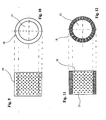
- the device implemented according to the invention consists of a chamber housing a hollow cylinder with perforated surface with a fine wire mesh strip wrapped around it.
- the molten plastic enters the space in the chamber not occupied by the hollow cylinder and under pressure crosses the mesh (which retains the impurities) and the perforated surface of the cylinder, finishing in the cavity of the above cylinder which communicates with the outlet.
- the section of mesh wrapped around the cylinder is part of a moving strip fed by an external coil which is clean when it enters the device on one side and after wrapping around the perforated hollow cylinder comes out clogged, as it is no longer efficient, on the opposite side of the device.
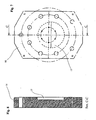
- the perforated hollow cylinder which is fitted in a floating manner inside the chamber of the device, is rotated by the forward movement of the mesh. It should be noted that the perforated hollow cylinder, at the head ends, provides the "seal" by moving adhering to the bottom walls of the cover and main block of the device in which it is contained without forcing. While the space of the chamber of the device not occupied by the perforated hollow cylinder communicates with the inlet of the contaminated molten plastic, the cavity of the perforated cylinder in which the clean molten plastic arrives communicates with the outlet, via which the clean material proceeds to the subsequent work phases without interruption.
- the pairs of drive rollers (which are automatically driven according to a specific program) positioned on the mesh inlet side draw new mesh from the external coil, while the pairs of rollers (which are also automatically driven according to a specific program) positioned on the outlet side of the mesh draw the mesh which is resting on the perforated hollow cylinder, conveying it to the outside to a winding reel.
- the two pairs of rollers generally rotate at the same speed, but if rotation of the outlet rollers is increased with respect to that of the inlet rollers, the section of mesh resting on the perforated hollow cylinder is tensioned, increasing adhesion on the surface of the perforated perforated hollow cylinder.
- the lower rollers cooperate with the upper ones to move the mesh.
- the seal for any molten material which, passing from the inside to the outside of the perforated hollow cylinder, flows out into the lower space not enveloped by the mesh, filling it and remaining there.
- a variation of the device as previously described consists in driving the perforated drum by means of a rotating apparatus via which it remains floating and rotates independently, but synchronised with the feed of the mesh that envelops it.
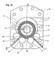
- a further variation in concomitance or otherwise with the variation that moves the perforated drum as described above consists in a different manner of sustaining the perforated roller. Without prejudice to the function of the rotating rollers for feeding the mesh positioned between them and the outer surface of the perforated drum and enveloping said drum, a further two motorised rollers which are not involved with the branch of incoming clean mesh strip and the branch of outgoing clogged mesh act as a support, resting directly on the lower section of the periphery of the drum.
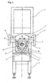
- the perforated hollow cylinder 18 is introduced into the cavity 9 and a coil (not visible in the figure) of fine wire mesh strip is fitted on the reel 21.
- One end of the strip 20 is inserted into the aperture 25 of the block 4, it is fed to the drive roller 13 and inserted between the supporting drive roller 11 of the cylinder 18. Having covered the outer surface of the roller 18 with the strip 20, the end of the strip is fed forward, inserting it between the supporting drive roller 12 and the roller 18, passes over the drive roller 14 and comes out of the aperture 25.
- the branch of outgoing wire mesh strip is hooked to the reel 23 ready for winding.
- the main block 4 of the device is connected to the extruder equipment provided with screw (not shown in the drawing) corresponding to the flange 5 via which the contaminated molten plastic is conveyed under pressure via the duct 7, filling the space 9 above the fine wire mesh resting on the hollow cylinder 18.
- the rollers 13, 11, 12, 14 are automatically rotated, feeding forward the clean portion of wire mesh strip 20, 22 until the programmed pressure value is restored.
- the cylinder 18 sustained in a floating manner by the rollers 11, 12 also rotates due to adhesion with the fine wire mesh.
- the clean molten plastic inside the hollow cylinder 18, which comes out of the holes of the cylinder 18 in the section not enveloped by the mesh 20, 22 between the rollers 11, 12 fills the space below, the seal of which is guaranteed by the floating roller 19, which prevents communication with the aperture 25 below of the main block 4 of the device.
- the seal to prevent leaking of the molten resin via the gap between the rollers 27 and 30 and the gap between the rollers 28 and 29 is provided by the presence, corresponding to said gaps respectively, of the floating roller 33 and the floating roller 34.
- the difference in the construction arrangement of the main block 26, provided with the rollers 29 and 30 (which can be motorised) that provide support at the bottom in direct contact with the periphery 18 of the perforated drum 18 reducing the compression of the wire mesh due to the load on the perforated drum 18 at the level of the rollers 27 and 28, does not modify the set-up procedure. From the above description it is evident that the device of the patent permits automatic processing without interruptions, 24 hours out of 24.
Landscapes
- Chemical & Material Sciences (AREA)
- Chemical Kinetics & Catalysis (AREA)
- Engineering & Computer Science (AREA)
- Mechanical Engineering (AREA)
- Extrusion Moulding Of Plastics Or The Like (AREA)
- Processing And Handling Of Plastics And Other Materials For Molding In General (AREA)
- Filtration Of Liquid (AREA)
Claims (7)
- Filtervorrichtung zur durchgehenden Filterung von geschmolzenem Kunststoffmaterial, bestehend aus einem Körper (4), der eine Öffnung (5) für die Zufuhr von dem zu filternden Kunststoffmaterial und eine Öffnung (6) für den Austritt des gefilterten Kunststoffmaterials hat und außerdem eine Öffnung (25) besitzt für den stetigen Ein- und Ausgang eines engmaschigen Metallnetzbands (20, 22), das von obengenannten Kunststoffmaterialen durchflossen wird und diese dabei von Unreinheiten befreit. Besagtes Metallnetzband in besagtem Körper (4) ist an die äußere Oberfläche eines durchlöcherten Hohlzylinders (18) gelegt, der sich um seine Hauptachse dreht. Ein Dichtungswalzenpaar (11, 12), das parallel zum durchlöcherten Hohlzylinder (18) liegt, grenzt das auf besagtem durchlöcherten Hohlzylinder (18) aufliegende Metallnetzbandstück ab. Dasselbe Dichtungswalzenpaar (11, 12) mit dem zwischen ihnen und dem durchlöcherten Hohlzylinder (18) liegenden Metallnetz, gewährleistet die Abdichtung gegen das geschmolzene Kunststoffmaterial, das durch die Öffnung (5) in die Vorrichtung gelangt. Die Abdichtung gegen das Austreten aus der Öffnung (25) des gefilterten Kunststoffmaterials - das vom Innenraum des durchlöcherten Hohlzylinders (18) am nicht vom Netz bedeckten Teil, der sich von der Auflage der Walzen (11, 12) bis zum gelöcherten Hohlzylinder (18) mit dem dazwischenliegenden Netz erstreckt, nach außen gelangt - wird von einem Walzenpaar (13, 14), welches die eintretenden (20) und austretenden (22) Netzenden begleitet und sie parallel und distanziert hält, und von einer dritten, schwimmenden, Walze (19) übernommen, die sich zur Unterstützung zentral im oberen Zwischenraum zwischen den obengenannten begleitenden Walzen (13, 14) mit den dazwischenliegenden eintretenden (20) und austretenden (22) Netzenden befindet.
- Filtervorrichtung zur durchgehenden Filterung von geschmolzenem Kunststoffmaterial, bestehend aus einem Körper (4), der eine Öffnung (5) für die Zufuhr von dem zu filternden Kunststoffmaterial und eine Öffnung (6) für den Austritt des gefilterten Kunststoffmaterials hat und außerdem eine Öffnung (25) besitzt für den stetigen Ein- und Ausgang eines engmaschigen Metallnetzbands (20, 22), das von obengenannten Kunststoffmaterialen durchflossen wird und diese dabei von Unreinheiten befreit. Besagtes Metallnetzband in besagtem Körper (4) ist an die äußere Oberfläche eines durchlöcherten Hohlzylinders (18) gelegt, der sich um seine Hauptachse dreht. Ein Walzenpaar (27, 28), das parallel zum durchlöcherten Hohlzylinder (18) liegt, grenzt das auf besagtem durchlöcherten Hohlzylinder (18) aufliegende Metallnetzbandstück ab. Dasselbe Walzenpaar (27, 28) mit dem zwischen ihnen und dem gelöcherten Hohlzylinder (18) liegenden Metallnetz, gewährleistet die Abdichtung gegen das geschmolzene Kunststoffmaterial, das durch die Öffnung (5) in die Vorrichtung gelangt. Dieser Vorgang ist erstens dadurch gekennzeichnet, dass der Körper (26) zwei Durchgänge für das Metallnetzband hat, einen im Eintrittsbereich (31) des Körpers (26) und einen im Austrittsbereich (32) des Körpers, und zweitens dass die Abdichtung gegen das Austreten durch die obengenannten Durchgänge (31, 32) des gefilterten Kunststoffmaterials, das vom Innenraum (15) des durchlöcherten Hohlzylinders (18) nach außen gelangt, folgendermaßen erzielt wird:a. Im Eintrittsbereich (31) wird die Abdichtung von zwei parallelen Walzen (27, 30), die den durchlöcherten Hohlzylinder (18) halten und von denen eine (30) in direktem Kontakt und die andere (27) in indirektem Kontakt (da das Eintrittsende des Netzes (20) dazwischenliegt) zum Zylinder steht, und von einer dritten kleinen schwimmenden Walze (33) übernommen, die sich zentral in der Öffnung zwischen den obengenannten parallelen Walzen (27, 30) befindet. Besagte schwimmende Walze (33) ist in direktem Kontakt mit einer (30) der beiden parallelen Walzen und in indirektem Kontakt mit der anderen (27), da dort das Eintrittsende des Metallnetzbandes (20) dazwischenliegt.b. Im Austrittsbereich (32) wird die Abdichtung von zwei parallelen Walzen (28, 29), die den durchlöcherten Hohlzylinder (18) halten und von denen eine (29) in direktem Kontakt und die andere (28) in indirektem Kontakt (da das Austrittsende des Netzes (22) dazwischenliegt) zum Zylinder steht, und von einer dritten kleinen schwimmenden Walze (34) übernommen, die sich zentral in der Öffnung zwischen den obengenannten parallelen Walzen (28, 29) befindet. Besagte schwimmende Walze (34) ist in direktem Kontakt mit einer (29) der beiden parallelen Walzen und in indirektem Kontakt mit der anderen (28), da dort das Austrittsende des Metallnetzbandes (22) dazwischenliegt.
- Filtervorrichtung gemäß Anspruch 1 oder 2, welche dadurch gekennzeichnet ist, dass der durchlöcherte Hohlzylinder (18) schwimmend gelagert ist. Dies ermöglicht dem an besagtem durchlöcherten Hohlzylinder (18) angelegten Metallnetzband, diesen gegen die Dichtungswalzen (11, 12) zu stemmen, wobei das Metallnetzband selbst dazwischenliegt. Auf diese Weise wird die Abdichtung des zu filternden Kunststoffmaterials, das sich im Innenraum (9) des Körpers befindet, erreicht.
- Filtervorrichtung gemäß Anspruch 1 oder 3, welche dadurch gekennzeichnet ist, dass das Gewicht der gelöcherten Walze (18) von den Antriebswalzen (11, 12) gehalten wird.
- Filtervorrichtung gemäß Anspruch 2 oder 3, welche dadurch gekennzeichnet ist, dass das Gewicht des durchlöcherten Hohlzylinders (18) von den unteren Dichtungswalzen (29, 30) gehalten wird. Dies ermöglicht eine Verteilung des auf das Metallband einwirkenden Drucks auf den durchlöcherten Hohlzylinder (18) und die Antriebswalzen (27, 28).
- Filtervorrichtung gemäß Anspruch 1, welche dadurch gekennzeichnet ist, dass der Körper (4) einen einzigen Durchgang (25) besitzt, der sowohl dem Eintritt des sauberen Bands (20) als auch dem Austritt des verstopften Bands (22) dient.
- Filtervorrichtung gemäß einem oder mehrerer der obigen Ansprüche, welche dadurch gekennzeichnet ist, dass das gefilterte Kunststoffmaterial durch eine Öffnung (24) des Körpers (4, 26) ausfließt, welche mit dem Hohlraum (15) des durchlöcherten Hohlzylinders (18) verbunden ist.
Applications Claiming Priority (2)
| Application Number | Priority Date | Filing Date | Title |
|---|---|---|---|
| ITPD20030310 | 2003-12-29 | ||
| IT000310A ITPD20030310A1 (it) | 2003-12-29 | 2003-12-29 | Dispositivo per il filtraggio in continuo per materie plastiche fuse |
Publications (2)
| Publication Number | Publication Date |
|---|---|
| EP1550544A1 EP1550544A1 (de) | 2005-07-06 |
| EP1550544B1 true EP1550544B1 (de) | 2008-06-18 |
Family
ID=34566925
Family Applications (1)
| Application Number | Title | Priority Date | Filing Date |
|---|---|---|---|
| EP04028907A Expired - Lifetime EP1550544B1 (de) | 2003-12-29 | 2004-12-07 | Vorrichtung zum kontinuierlichen Filtern eines geschmolzenen Kunststoffes |
Country Status (5)
| Country | Link |
|---|---|
| EP (1) | EP1550544B1 (de) |
| AT (1) | ATE398519T1 (de) |
| DE (1) | DE602004014466D1 (de) |
| ES (1) | ES2305653T3 (de) |
| IT (1) | ITPD20030310A1 (de) |
Cited By (1)
| Publication number | Priority date | Publication date | Assignee | Title |
|---|---|---|---|---|
| US20220062803A1 (en) * | 2020-09-01 | 2022-03-03 | Fimic S.R.L. | Device for the continuous filteration of molten plastic material |
Families Citing this family (7)
| Publication number | Priority date | Publication date | Assignee | Title |
|---|---|---|---|---|
| KR100847446B1 (ko) | 2007-08-02 | 2008-07-21 | (주)흥원피앤엠 | 합성수지 성형기의 자동 스크린 교체장치 |
| KR101038366B1 (ko) | 2011-02-14 | 2011-06-01 | 이상대 | 합성수지 압출기용 스크린 교체장치 |
| KR101375726B1 (ko) | 2013-07-08 | 2014-03-19 | (주)더원알앤씨 | 플라스틱 압출기용 스크린필터장치 |
| CN104552882B (zh) * | 2015-01-05 | 2017-02-22 | 舟山市安格机械有限公司 | 一种挤出机过滤装置 |
| US10807295B2 (en) | 2015-02-19 | 2020-10-20 | Next Generation Analytics Gmbh | Filter device and filter method |
| CN111330327A (zh) * | 2020-04-23 | 2020-06-26 | 郑州德奥科技有限公司 | 一种熔体过滤器 |
| CN116603300B (zh) * | 2023-06-26 | 2026-07-17 | 洛阳科丰冶金新材料有限公司 | 一种浆料过滤装置 |
Family Cites Families (5)
| Publication number | Priority date | Publication date | Assignee | Title |
|---|---|---|---|---|
| DE1757865B1 (de) * | 1968-06-22 | 1971-11-11 | Delbag Luftfilter Gmbh | Trommelfilter zum Abscheiden fester Teilchen aus einem Gas-Strom |
| GB1285702A (en) * | 1968-09-03 | 1972-08-16 | Peter Gabor Kalman | Filtering apparatus |
| JPS5196857A (en) * | 1975-02-20 | 1976-08-25 | Oshidashikino jidoromokokansochi | |
| JPS61175016A (ja) * | 1985-01-31 | 1986-08-06 | Tomy Kikai Kogyo Kk | 回転するスクリ−ンを備える押出機 |
| US5320753A (en) * | 1991-06-18 | 1994-06-14 | The Dow Chemical Company | Continuous filter |
-
2003
- 2003-12-29 IT IT000310A patent/ITPD20030310A1/it unknown
-
2004
- 2004-12-07 DE DE602004014466T patent/DE602004014466D1/de not_active Expired - Lifetime
- 2004-12-07 EP EP04028907A patent/EP1550544B1/de not_active Expired - Lifetime
- 2004-12-07 AT AT04028907T patent/ATE398519T1/de active
- 2004-12-07 ES ES04028907T patent/ES2305653T3/es not_active Expired - Lifetime
Cited By (2)
| Publication number | Priority date | Publication date | Assignee | Title |
|---|---|---|---|---|
| US20220062803A1 (en) * | 2020-09-01 | 2022-03-03 | Fimic S.R.L. | Device for the continuous filteration of molten plastic material |
| US11813556B2 (en) * | 2020-09-01 | 2023-11-14 | Fimic S.R.L. | Device for the continuous filtration of molten plastic material |
Also Published As
| Publication number | Publication date |
|---|---|
| EP1550544A1 (de) | 2005-07-06 |
| DE602004014466D1 (de) | 2008-07-31 |
| ATE398519T1 (de) | 2008-07-15 |
| ITPD20030310A1 (it) | 2005-06-30 |
| ES2305653T3 (es) | 2008-11-01 |
Similar Documents
| Publication | Publication Date | Title |
|---|---|---|
| US5299407A (en) | Process and device for avoiding strapping-caused downtime on machine for strapping packages | |
| DE3150575C2 (de) | ||
| JP3380270B2 (ja) | 高圧ろ過室用ろ過ベルト装置 | |
| EP1550544A1 (de) | Vorrichtung zum kontinuierlichen Filtern eines geschmolzenen Kunststoffes | |
| CN112590223B (zh) | 用于连续生产口罩复合布的设备 | |
| US5320753A (en) | Continuous filter | |
| CN105127062A (zh) | 烟草加工业的材料带的施胶 | |
| KR101891800B1 (ko) | 솜사탕 제조장치 | |
| CN114055017B (zh) | 一种焊条自动生产系统 | |
| EP2662196A1 (de) | Vorrichtung zur Behandlung von Pulvermaterial | |
| US5112485A (en) | Drum filter | |
| US3499532A (en) | Liquid filtering device | |
| CN115249575B (zh) | 一种具有保护功能的开口铁芯自动卷绕机 | |
| CN108466404A (zh) | 一种造粒机不停机换网器 | |
| KR100189476B1 (ko) | 물질에서 오염물질을 여과하는 방법 및 장치 | |
| JP3071100B2 (ja) | ワイヤソーにおけるスラリー供給装置 | |
| CN216634942U (zh) | 一种切片机 | |
| DE4325159C2 (de) | Vorrichtung zum Aufwickeln und Flachdrücken der Umfangshülle einer Materialbahn-Rolle | |
| US3791527A (en) | Rotary filter apparatus | |
| CN114229565A (zh) | 一种双玻封边胶带的分条打孔设备及打孔方法 | |
| US10730648B2 (en) | Device and method for producing fascines | |
| CN221641463U (zh) | 一种塑料挤出料杂质过滤装置 | |
| KR100544977B1 (ko) | 유동성 폐기물 처리 장치 | |
| US3040495A (en) | Filtering means | |
| CN114834937B (zh) | 一种改性塑料造粒机 |
Legal Events
| Date | Code | Title | Description |
|---|---|---|---|
| PUAI | Public reference made under article 153(3) epc to a published international application that has entered the european phase |
Free format text: ORIGINAL CODE: 0009012 |
|
| AK | Designated contracting states |
Kind code of ref document: A1 Designated state(s): AT BE BG CH CY CZ DE DK EE ES FI FR GB GR HU IE IS IT LI LT LU MC NL PL PT RO SE SI SK TR |
|
| AX | Request for extension of the european patent |
Extension state: AL BA HR LV MK YU |
|
| 17P | Request for examination filed |
Effective date: 20050922 |
|
| AKX | Designation fees paid |
Designated state(s): AT BE BG CH CY CZ DE DK EE ES FI FR GB GR HU IE IS IT LI LT LU MC NL PL PT RO SE SI SK TR |
|
| 17Q | First examination report despatched |
Effective date: 20051019 |
|
| GRAP | Despatch of communication of intention to grant a patent |
Free format text: ORIGINAL CODE: EPIDOSNIGR1 |
|
| GRAS | Grant fee paid |
Free format text: ORIGINAL CODE: EPIDOSNIGR3 |
|
| GRAA | (expected) grant |
Free format text: ORIGINAL CODE: 0009210 |
|
| AK | Designated contracting states |
Kind code of ref document: B1 Designated state(s): AT BE BG CH CY CZ DE DK EE ES FI FR GB GR HU IE IS IT LI LT LU MC NL PL PT RO SE SI SK TR |
|
| REG | Reference to a national code |
Ref country code: GB Ref legal event code: FG4D |
|
| REF | Corresponds to: |
Ref document number: 602004014466 Country of ref document: DE Date of ref document: 20080731 Kind code of ref document: P |
|
| REG | Reference to a national code |
Ref country code: CH Ref legal event code: EP |
|
| REG | Reference to a national code |
Ref country code: IE Ref legal event code: FG4D |
|
| PG25 | Lapsed in a contracting state [announced via postgrant information from national office to epo] |
Ref country code: SI Free format text: LAPSE BECAUSE OF FAILURE TO SUBMIT A TRANSLATION OF THE DESCRIPTION OR TO PAY THE FEE WITHIN THE PRESCRIBED TIME-LIMIT Effective date: 20080618 Ref country code: FI Free format text: LAPSE BECAUSE OF FAILURE TO SUBMIT A TRANSLATION OF THE DESCRIPTION OR TO PAY THE FEE WITHIN THE PRESCRIBED TIME-LIMIT Effective date: 20080618 |
|
| REG | Reference to a national code |
Ref country code: ES Ref legal event code: FG2A Ref document number: 2305653 Country of ref document: ES Kind code of ref document: T3 |
|
| PG25 | Lapsed in a contracting state [announced via postgrant information from national office to epo] |
Ref country code: PL Free format text: LAPSE BECAUSE OF FAILURE TO SUBMIT A TRANSLATION OF THE DESCRIPTION OR TO PAY THE FEE WITHIN THE PRESCRIBED TIME-LIMIT Effective date: 20080618 |
|
| PGFP | Annual fee paid to national office [announced via postgrant information from national office to epo] |
Ref country code: IE Payment date: 20080926 Year of fee payment: 5 |
|
| ET | Fr: translation filed | ||
| PG25 | Lapsed in a contracting state [announced via postgrant information from national office to epo] |
Ref country code: PT Free format text: LAPSE BECAUSE OF FAILURE TO SUBMIT A TRANSLATION OF THE DESCRIPTION OR TO PAY THE FEE WITHIN THE PRESCRIBED TIME-LIMIT Effective date: 20081118 Ref country code: LT Free format text: LAPSE BECAUSE OF FAILURE TO SUBMIT A TRANSLATION OF THE DESCRIPTION OR TO PAY THE FEE WITHIN THE PRESCRIBED TIME-LIMIT Effective date: 20080618 Ref country code: IS Free format text: LAPSE BECAUSE OF FAILURE TO SUBMIT A TRANSLATION OF THE DESCRIPTION OR TO PAY THE FEE WITHIN THE PRESCRIBED TIME-LIMIT Effective date: 20081018 Ref country code: CZ Free format text: LAPSE BECAUSE OF FAILURE TO SUBMIT A TRANSLATION OF THE DESCRIPTION OR TO PAY THE FEE WITHIN THE PRESCRIBED TIME-LIMIT Effective date: 20080618 Ref country code: SE Free format text: LAPSE BECAUSE OF FAILURE TO SUBMIT A TRANSLATION OF THE DESCRIPTION OR TO PAY THE FEE WITHIN THE PRESCRIBED TIME-LIMIT Effective date: 20080918 |
|
| PGFP | Annual fee paid to national office [announced via postgrant information from national office to epo] |
Ref country code: CH Payment date: 20081107 Year of fee payment: 5 Ref country code: LU Payment date: 20081006 Year of fee payment: 5 Ref country code: NL Payment date: 20081001 Year of fee payment: 5 |
|
| PG25 | Lapsed in a contracting state [announced via postgrant information from national office to epo] |
Ref country code: RO Free format text: LAPSE BECAUSE OF FAILURE TO SUBMIT A TRANSLATION OF THE DESCRIPTION OR TO PAY THE FEE WITHIN THE PRESCRIBED TIME-LIMIT Effective date: 20080618 Ref country code: SK Free format text: LAPSE BECAUSE OF FAILURE TO SUBMIT A TRANSLATION OF THE DESCRIPTION OR TO PAY THE FEE WITHIN THE PRESCRIBED TIME-LIMIT Effective date: 20080618 |
|
| PGFP | Annual fee paid to national office [announced via postgrant information from national office to epo] |
Ref country code: BE Payment date: 20080930 Year of fee payment: 5 |
|
| PLBE | No opposition filed within time limit |
Free format text: ORIGINAL CODE: 0009261 |
|
| STAA | Information on the status of an ep patent application or granted ep patent |
Free format text: STATUS: NO OPPOSITION FILED WITHIN TIME LIMIT |
|
| PG25 | Lapsed in a contracting state [announced via postgrant information from national office to epo] |
Ref country code: EE Free format text: LAPSE BECAUSE OF FAILURE TO SUBMIT A TRANSLATION OF THE DESCRIPTION OR TO PAY THE FEE WITHIN THE PRESCRIBED TIME-LIMIT Effective date: 20080618 Ref country code: BG Free format text: LAPSE BECAUSE OF FAILURE TO SUBMIT A TRANSLATION OF THE DESCRIPTION OR TO PAY THE FEE WITHIN THE PRESCRIBED TIME-LIMIT Effective date: 20080918 Ref country code: DK Free format text: LAPSE BECAUSE OF FAILURE TO SUBMIT A TRANSLATION OF THE DESCRIPTION OR TO PAY THE FEE WITHIN THE PRESCRIBED TIME-LIMIT Effective date: 20080618 |
|
| 26N | No opposition filed |
Effective date: 20090319 |
|
| PG25 | Lapsed in a contracting state [announced via postgrant information from national office to epo] |
Ref country code: MC Free format text: LAPSE BECAUSE OF NON-PAYMENT OF DUE FEES Effective date: 20081231 |
|
| BERE | Be: lapsed |
Owner name: F.I.M.I.C. S.N.C. Effective date: 20091231 |
|
| REG | Reference to a national code |
Ref country code: NL Ref legal event code: V1 Effective date: 20100701 |
|
| PG25 | Lapsed in a contracting state [announced via postgrant information from national office to epo] |
Ref country code: CY Free format text: LAPSE BECAUSE OF FAILURE TO SUBMIT A TRANSLATION OF THE DESCRIPTION OR TO PAY THE FEE WITHIN THE PRESCRIBED TIME-LIMIT Effective date: 20080618 Ref country code: HU Free format text: LAPSE BECAUSE OF FAILURE TO SUBMIT A TRANSLATION OF THE DESCRIPTION OR TO PAY THE FEE WITHIN THE PRESCRIBED TIME-LIMIT Effective date: 20081219 |
|
| REG | Reference to a national code |
Ref country code: CH Ref legal event code: PL |
|
| PG25 | Lapsed in a contracting state [announced via postgrant information from national office to epo] |
Ref country code: TR Free format text: LAPSE BECAUSE OF FAILURE TO SUBMIT A TRANSLATION OF THE DESCRIPTION OR TO PAY THE FEE WITHIN THE PRESCRIBED TIME-LIMIT Effective date: 20080618 |
|
| REG | Reference to a national code |
Ref country code: IE Ref legal event code: MM4A |
|
| PG25 | Lapsed in a contracting state [announced via postgrant information from national office to epo] |
Ref country code: CH Free format text: LAPSE BECAUSE OF NON-PAYMENT OF DUE FEES Effective date: 20091231 Ref country code: GR Free format text: LAPSE BECAUSE OF FAILURE TO SUBMIT A TRANSLATION OF THE DESCRIPTION OR TO PAY THE FEE WITHIN THE PRESCRIBED TIME-LIMIT Effective date: 20080919 Ref country code: IE Free format text: LAPSE BECAUSE OF NON-PAYMENT OF DUE FEES Effective date: 20091207 Ref country code: LI Free format text: LAPSE BECAUSE OF NON-PAYMENT OF DUE FEES Effective date: 20091231 Ref country code: NL Free format text: LAPSE BECAUSE OF NON-PAYMENT OF DUE FEES Effective date: 20100701 Ref country code: BE Free format text: LAPSE BECAUSE OF NON-PAYMENT OF DUE FEES Effective date: 20091231 |
|
| PG25 | Lapsed in a contracting state [announced via postgrant information from national office to epo] |
Ref country code: LU Free format text: LAPSE BECAUSE OF NON-PAYMENT OF DUE FEES Effective date: 20091207 |
|
| REG | Reference to a national code |
Ref country code: FR Ref legal event code: PLFP Year of fee payment: 12 |
|
| REG | Reference to a national code |
Ref country code: FR Ref legal event code: PLFP Year of fee payment: 13 |
|
| REG | Reference to a national code |
Ref country code: FR Ref legal event code: PLFP Year of fee payment: 14 |
|
| REG | Reference to a national code |
Ref country code: FR Ref legal event code: PLFP Year of fee payment: 15 |
|
| REG | Reference to a national code |
Ref country code: DE Ref legal event code: R079 Ref document number: 602004014466 Country of ref document: DE Free format text: PREVIOUS MAIN CLASS: B29C0047680000 Ipc: B29C0048690000 |
|
| PGFP | Annual fee paid to national office [announced via postgrant information from national office to epo] |
Ref country code: DE Payment date: 20201116 Year of fee payment: 17 Ref country code: IT Payment date: 20201113 Year of fee payment: 17 Ref country code: GB Payment date: 20201113 Year of fee payment: 17 Ref country code: FR Payment date: 20201113 Year of fee payment: 17 Ref country code: AT Payment date: 20201116 Year of fee payment: 17 |
|
| PGFP | Annual fee paid to national office [announced via postgrant information from national office to epo] |
Ref country code: ES Payment date: 20210111 Year of fee payment: 17 |
|
| REG | Reference to a national code |
Ref country code: DE Ref legal event code: R119 Ref document number: 602004014466 Country of ref document: DE |
|
| REG | Reference to a national code |
Ref country code: AT Ref legal event code: MM01 Ref document number: 398519 Country of ref document: AT Kind code of ref document: T Effective date: 20211207 |
|
| GBPC | Gb: european patent ceased through non-payment of renewal fee |
Effective date: 20211207 |
|
| PG25 | Lapsed in a contracting state [announced via postgrant information from national office to epo] |
Ref country code: GB Free format text: LAPSE BECAUSE OF NON-PAYMENT OF DUE FEES Effective date: 20211207 Ref country code: DE Free format text: LAPSE BECAUSE OF NON-PAYMENT OF DUE FEES Effective date: 20220701 Ref country code: AT Free format text: LAPSE BECAUSE OF NON-PAYMENT OF DUE FEES Effective date: 20211207 |
|
| PG25 | Lapsed in a contracting state [announced via postgrant information from national office to epo] |
Ref country code: FR Free format text: LAPSE BECAUSE OF NON-PAYMENT OF DUE FEES Effective date: 20211231 |
|
| PG25 | Lapsed in a contracting state [announced via postgrant information from national office to epo] |
Ref country code: IT Free format text: LAPSE BECAUSE OF NON-PAYMENT OF DUE FEES Effective date: 20211207 |
|
| REG | Reference to a national code |
Ref country code: ES Ref legal event code: FD2A Effective date: 20230217 |
|
| PG25 | Lapsed in a contracting state [announced via postgrant information from national office to epo] |
Ref country code: ES Free format text: LAPSE BECAUSE OF NON-PAYMENT OF DUE FEES Effective date: 20211208 |