EP1550467B1 - Dispositif de test pour contrôler les propriétés de pénétration d'un agent de stérilisation dans des procédés de stérilisation - Google Patents
Dispositif de test pour contrôler les propriétés de pénétration d'un agent de stérilisation dans des procédés de stérilisation Download PDFInfo
- Publication number
- EP1550467B1 EP1550467B1 EP03028828A EP03028828A EP1550467B1 EP 1550467 B1 EP1550467 B1 EP 1550467B1 EP 03028828 A EP03028828 A EP 03028828A EP 03028828 A EP03028828 A EP 03028828A EP 1550467 B1 EP1550467 B1 EP 1550467B1
- Authority
- EP
- European Patent Office
- Prior art keywords
- indicator
- detector
- test device
- volume
- sterilization
- Prior art date
- Legal status (The legal status is an assumption and is not a legal conclusion. Google has not performed a legal analysis and makes no representation as to the accuracy of the status listed.)
- Expired - Lifetime
Links
Images

Classifications
-
- A—HUMAN NECESSITIES
- A61—MEDICAL OR VETERINARY SCIENCE; HYGIENE
- A61L—METHODS OR APPARATUS FOR STERILISING MATERIALS OR OBJECTS IN GENERAL; DISINFECTION, STERILISATION OR DEODORISATION OF AIR; CHEMICAL ASPECTS OF BANDAGES, DRESSINGS, ABSORBENT PADS OR SURGICAL ARTICLES; MATERIALS FOR BANDAGES, DRESSINGS, ABSORBENT PADS OR SURGICAL ARTICLES
- A61L2/00—Disinfection or sterilisation of materials or objects, in general; Accessories therefor
- A61L2/26—Accessories
- A61L2/28—Devices for testing the effectiveness or completeness of sterilisation or disinfection, e.g. indicators which change colour
-
- C—CHEMISTRY; METALLURGY
- C12—BIOCHEMISTRY; BEER; SPIRITS; WINE; VINEGAR; MICROBIOLOGY; ENZYMOLOGY; MUTATION OR GENETIC ENGINEERING
- C12Q—MEASURING OR TESTING PROCESSES INVOLVING ENZYMES, NUCLEIC ACIDS OR MICROORGANISMS; COMPOSITIONS OR TEST PAPERS THEREFOR; PROCESSES OF PREPARING SUCH COMPOSITIONS; CONDITION-RESPONSIVE CONTROL IN MICROBIOLOGICAL OR ENZYMOLOGICAL PROCESSES
- C12Q1/00—Measuring or testing processes involving enzymes, nucleic acids or microorganisms; Compositions therefor; Processes of preparing such compositions
- C12Q1/02—Measuring or testing processes involving enzymes, nucleic acids or microorganisms; Compositions therefor; Processes of preparing such compositions involving viable microorganisms
- C12Q1/22—Testing for sterility conditions
-
- G—PHYSICS
- G01—MEASURING; TESTING
- G01N—INVESTIGATING OR ANALYSING MATERIALS BY DETERMINING THEIR CHEMICAL OR PHYSICAL PROPERTIES
- G01N31/00—Investigating or analysing non-biological materials by the use of the chemical methods specified in the subgroup; Apparatus specially adapted for such methods
- G01N31/22—Investigating or analysing non-biological materials by the use of the chemical methods specified in the subgroup; Apparatus specially adapted for such methods using chemical indicators
- G01N31/226—Investigating or analysing non-biological materials by the use of the chemical methods specified in the subgroup; Apparatus specially adapted for such methods using chemical indicators for investigating the degree of sterilisation
Definitions
- the invention relates to a test specimen in hollow body construction according to claim 1. It further relates to a method for producing such a specimen.
- Such specimens are for example from the EP 0 628 814 A1 or from the EP 1 172 117 A2 known.
- the sterilizing medium such as steam, formaldehyde, ethylene oxide, hydrogen peroxide and / or ozone
- Sterilizers with sterilization chambers are usually used for this purpose, into which the instruments or materials to be sterilized are inserted, usually packaged.
- the sterilization chamber is flooded with gaseous sterilizing agent - also referred to as a sterilizing agent -, whereby the removal of the air atmosphere must first be ensured.
- the sterilant should contact the surfaces of the instruments or materials to be sterilized so that the desired germ kill occurs.
- the complete sterilization of the goods is ensured at all points only if the sterilant also reaches all internal surfaces, eg. B. porous goods or hollow body is the beginning of the sterilization process, the removal to ensure the air inside the goods and inside the sterilization room by means of a suitable deaeration process. Subsequently, the sterilization chamber is flooded with the sterilizing agent to reach inside the sterilization chamber all surfaces of the equipment with the sterilizing agent. This is only possible if the complete penetration of the sterilant on all surfaces is guaranteed.
- chemo-indicators can be used which, in the event of wetting of their surface by the sterilant under the influence of temperature, such as steam, change their color, so that it is immediately apparent that a contact actually took place at the site of the chemo indicator.
- bio-indicators which are used in the form of strips, suspensions or self-developing seed cultures or mixtures of different seed cultures, in which it is checked after the sterilization measure has been carried out whether all the germs have been completely inactivated.
- test specimens or specimen systems can be used.
- test body system as for example in the EP 0 628 814 A1 or described in EN 867-5, the inaccessible inner surface of complex instruments is modeled by a suitable model, by means of which the success of the penetration processes can be analogously verified even for complex instruments.
- PCD Process Challenge Device
- the hollow body system simulates the behavior of similarly designed instruments which are intended for sterilization, with residual air or other non-condensable gases remaining at the end of the hose and thus in the region of the still remaining residual air or other non-condensable gases, especially in the case of alternating media exchange in the manner of a fractionated vacuum and / or condensation Detector be concentrated.
- the tube thus acts as a gas collection chamber for residual air or other non-condensable gases, the detector is connected via this gas collection chamber by placing in the sterilization chamber with the sterilization room.
- test specimens also makes it possible to use physical measuring methods under certain boundary conditions.
- a test system for sterilization measures with a test specimen in which the local temperature change associated with the local condensation of steam at the point to be monitored is measured as evidence of a wetting of an inner surface by means of sterilizing agents becomes.
- the test specimen used in this system is therefore dimensioned particularly suitable in terms of its heat conduction properties.
- the invention is therefore based on the object of specifying a test specimen of the abovementioned type with which particularly reliable test results can be achieved with a particularly low outlay. Furthermore, a method for producing such a test specimen is to be specified.
- test specimens in hollow body construction which are intended for multiple use and thus necessarily include a reusable recording system for the indicator
- inventive, designed as a disposable test specimen is designed for its irreversible destruction in the removal of the indicator.
- the invention is based on the consideration that the reliability of the test results in the use of test specimens in hollow body construction can be kept very high by conceivable contamination, impurities and in particular residues of condensate or sterilant from a previous use in für Mikrosystem are consistently avoided. Especially the multiple use of such a specimen could contribute to the contamination or contamination of the entire system, so that before reuse of the für Mikrosystems a comparatively complicated cleaning and test for cleanliness and tightness is necessary. In contrast, ensures only a single use of such scholar analysessystems particularly high protection against the above changes.
- the test specimen is consistently designed as a disposable product with regard to the structural design of its components and the choice of materials.
- a particularly simple and cost-effective production is achieved by the indicator used is embedded at a hose end and the hose end is then welded to form the detector chamber.
- the tube can be suitably formed for an optical evaluation of the test results in an advantageous embodiment of transparent plastic.
- the gas collecting space is advantageously provided with a heat-insulating sheath.
- the gas collecting space is preferably designed in the manner of a spiral, preferably by deep drawing or spraying a plastic part.
- the hose can be rolled into a helix and held together with cable ties or other connecting parts.
- the detector space is advantageously provided with a predetermined breaking point. Just by the destruction of the detector chamber during the removal of the indicator is thereby ensured that in the sense of the intended use of the test specimen a single use is adhered to.
- a particularly high detection sensitivity of the test specimen is achievable in that the gas collecting space is designed to be multi-stage in a particularly advantageous embodiment, the cross section and / or the volume of each stage decreasing between adjacent stages in the direction of the detector chamber.
- the gas collecting space is designed to be multi-stage in a particularly advantageous embodiment, the cross section and / or the volume of each stage decreasing between adjacent stages in the direction of the detector chamber.
- An indicator may be a so-called physical indicator, ie a system for determining physical characteristics, such as a humidity, temperature, pressure and / or ultrasound sensor, which is located in the detector chamber, which may also be used as so-called data Logger for a wireless transmission of the recorded data can be configured. Also, for example, solids, such. As salts, be used, which physically change in the presence of the sterilant, so for example, change their melting point or their color. Furthermore, a so-called chemo-indicator, which changes color upon contact with the sterilant used, or a bio-indicator, for example in the form of indicator strips and / or self-developing bio-indicators, may be provided as an indicator.
- a so-called physical indicator ie a system for determining physical characteristics, such as a humidity, temperature, pressure and / or ultrasound sensor, which is located in the detector chamber, which may also be used as so-called data Logger for a wireless transmission of the recorded data can be configured.
- an indicator indicator in a particularly advantageous embodiment on a transparent inner wall of the detector chamber forming housing applied indicator color is provided.
- the indicator is mechanically firmly integrated with parts of the housing forming the detector space, so that separate support or support structures for the indicator can be omitted as such. Due to the design of the test specimen as a disposable product, the indicator can be removed together with the housing parts of the detector chamber carrying it after its use and suitably inspected and possibly archived.
- the stated object is achieved by applying to the inner wall of a tube piece provided for providing a detector space a suspension of a chemo or bio-indicator and then dried.
- the test specimen available is designed as a disposable product, in this way a particularly simple and thus cost-effective production of the specimen is guaranteed.
- the advantages achieved by the invention are in particular that the impairment of the test results due to residues of the sterilizing agent from previous processes, impurities or contamination can be kept to a particularly low level by the consistent design just a running in hollow body test specimen as a disposable product.
- a particularly high reliability and reproducibility in the determination of the inspection results can be achieved.
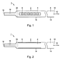
- the test piece 1 according to Fig. 1 is designed to check the penetration properties of a sterilant.
- the obtained when using the specimen 1 Insights can be used in particular for verifying or checking sterilization measures in a steam sterilization process.
- the instruments or materials to be sterilized are introduced into a sterilization chamber, not shown.
- the sterilization chamber is first vented. The venting process can thereby be carried out by flow processes, overpressure or vacuum venting cycles or a combination thereof.
- test piece 1 becomes for example the validation of the sterilization measure used in the sterilization chamber during commissioning or during routine checks during the sterilization process.
- the test specimen 1 comprises a detector 2, which is designed for specific detection that wetting by sterilizing agents has actually taken place.
- the test specimen 1 is designed to emulate the proper wetting and comparatively difficult accessible inner surfaces of instruments or materials suitable.
- the specimen 1 is designed in a so-called hollow body design.
- the detector 2 comprises an indicator 6 arranged in a detector chamber 4, which is designed to be suitable for detecting wetting by the sterilizing agent.
- the gas detector chamber 4 is upstream of a gas collection chamber 8, the end opening 10 is held open.
- the detector 2 as indicated by the double arrow 12, connected via the gas collection chamber 8 on the gas side with the sterilization chamber.
- the test specimen 1 is designed in particular for use in a steam-based sterilization method using a sterilization chamber with particularly high detection accuracy.
- the test specimen 1 together with the instruments or materials to be sterilized in the sterilization chamber brought in.
- the gas collection chamber 8 and the detector chamber 4 are also evacuated.
- the vapor also flows via the end orifice 10 into the gas collecting space 8 and via this into the detector space 4. Any remaining air that could prevent reliable sterilization of the instruments or materials through the formation of air cushions is thereby pressed into the detector chamber 4 via the gas collection chamber 8.
- a concentration of the residual air in the region of the detector 2 so that a complete wetting of the arranged in the detector 2 indicator 6 is omitted with the steam provided as a sterilizing agent.
- the indicator 6, according to the embodiment Fig. 1 occupies a volume of about 120 ul and the detector space 4 thus fills approximately half, could be designed as a sensor for determining a physical measurement value, for example, the temperature or the pressure.
- indicator 6 is a biochemical or chemo indicator.
- a bio-indicator of the indicator 6 is thereby added on its surface with germinable cultures, which are killed in a proper wetting with steam as a sterilant.
- the indicator 6 is thus used in such a way that after sterilization a review is made on germs that are still capable of reproduction. If such are found, inadequate sterilization is inferred.
- the indicator 6 as a chemo indicator this is designed such that it changes its color when wetted with steam as the sterilizing agent under the action of temperature over a predetermined time, so that closed by optical control directly to a continuous wetting can. If not wetted, no or another color change occurs.
- test specimen 1 The executed in hollow body test specimen 1 is designed to ensure particularly reliable test results with high reproducibility and at particularly low cost.
- the test specimen 1 is designed as a disposable product. This design manifests itself inter alia in the fact that with regard to the selection of the materials used, the dimensioning of the individual components and the like, the test specimen 1 is intended for a single use only and not for reuse.
- the detector chamber 4 and / or the gas collection chamber 8 may each be formed of metal.
- the detector chamber 4 and the gas collection chamber 8 are each formed as a piece of tubing.
- the pieces of hose forming the detector chamber 4 and the gas collection chamber 8 can be designed differently from one another, in particular with regard to the choice of material, the dimensioning and / or the flow cross section for the gas.
- the test specimen 1 is designed for a particularly simple design, wherein the detector chamber 4 and the gas collection chamber 8 are formed in the manner of a one-piece design by a common hose body 14.
- the hose body 14 is made of transparent plastic, so that a determination of the test results is made possible by optical evaluation, in particular by observation of the indicator 6.
- test piece 1 A particularly cost-effective production of the test piece 1 according to Fig. 1 is possible by the indicator 6 is introduced into a hose end of the hose body 14 and embedded there, wherein then the corresponding end of the hose 16 is welded. This creates the in Fig. 1 indicated weld 18.
- the housing forming the detector chamber 4 Due to the design of the specimen 1 as a disposable product, a non-destructive removal of the indicator 6 from the detector chamber 4 after verification measure neither provided nor required. Instead, when the indicator 6 is removed, the housing forming the detector chamber 4 is broken up, with the remaining remainder of the test piece 1 subsequently being able to be disposed of. In order to facilitate the removal of the indicator 6, the housing forming the detector chamber 4 has a predetermined breaking point 20, that is to say in particular a suitably predetermined weak point in the wall material.
- the detector chamber 4 may be surrounded by a heat-insulating sheath.
- Fig. 2 an alternative embodiment of the specimen 1 'is shown, in which an indicator 6 is provided on an inner transparent wall of the detector chamber 4 forming piece of tubing applied indicator color.
- an indicator 6 is provided on an inner transparent wall of the detector chamber 4 forming piece of tubing applied indicator color.
- a suspension of a chemo-indicator is then dried.
- execution of the specimen 1 'of the indicator 6 and the detector chamber 4 forming piece of hose of the hose body 14 thus form a mechanically integrated unit in which the indicator 6 is not readily removable from the corresponding piece of hose is.
- a storage of the indicator 6 may be provided together with the tube piece carrying it.
- the test body 1 is designed for a particularly compact design with at the same time particularly high detection sensitivity with regard to the penetration characteristics of the instruments or equipment to be simulated
- the gas collection chamber 8 is designed in several stages, with a first stage 22 immediately adjacent to the detector 2 on the gas side with further Of course, in addition to such a three-stage design, even further stages can be connected in series, or a two-stage design can be provided.
- a according to the construction scheme according to Fig. 3 constructed specimen 1 '"is in Fig. 4 shown nested.
- Its detector 2 comprises an intended for forming the detector chamber 4 and for receiving the indicator 6, by injection molding produced detector housing 28 which is connected to a provided for forming the first stage 22 of the gas collection chamber 8 hose piece 30.
- the first stage 22 of the gas collection chamber 8 is guided in the manner of a nested construction within the second stage 24 of the gas collection chamber 8.
- test body 1 is designed for a particularly high detection sensitivity with a particularly compact design
- first stage 22 in this embodiment is shown in FIG the type of a helix or wound spiral within the second stage 24 enclosing outer housing 32 out.
Landscapes
- Life Sciences & Earth Sciences (AREA)
- Health & Medical Sciences (AREA)
- Chemical & Material Sciences (AREA)
- Organic Chemistry (AREA)
- General Health & Medical Sciences (AREA)
- Immunology (AREA)
- Molecular Biology (AREA)
- Physics & Mathematics (AREA)
- Public Health (AREA)
- Analytical Chemistry (AREA)
- Biophysics (AREA)
- Proteomics, Peptides & Aminoacids (AREA)
- Engineering & Computer Science (AREA)
- Biochemistry (AREA)
- Zoology (AREA)
- Wood Science & Technology (AREA)
- Epidemiology (AREA)
- Veterinary Medicine (AREA)
- Microbiology (AREA)
- Animal Behavior & Ethology (AREA)
- Biotechnology (AREA)
- Bioinformatics & Cheminformatics (AREA)
- General Engineering & Computer Science (AREA)
- Genetics & Genomics (AREA)
- General Physics & Mathematics (AREA)
- Pathology (AREA)
- Apparatus For Disinfection Or Sterilisation (AREA)
- Measuring Or Testing Involving Enzymes Or Micro-Organisms (AREA)
- Sampling And Sample Adjustment (AREA)
Claims (9)
- Corps de contrôle (1, 1', 1 ", 1"') sous forme de corps creux, destiné en particulier au contrôle des caractéristiques de pénétration d'un produit stérilisant dans un processus de stérilisation, qui comprend un volume détecteur (4) pourvu d'un indicateur (6) et un collecteur de gaz (8) formé par un tuyau en matière plastique relié avec lui du côté du collecteur de gaz, corps de contrôle conçu comme produit jetable en sorte qu'il est détruit de manière irréversible si l'indicateur (6) est retiré, cet indicateur (6) étant intégré à une extrémité du tuyau et le bout du tuyau étant soudé pour former le volume détecteur (4).
- Corps de contrôle (1, 1', 1'', 1''') selon spécification 1, dont le collecteur de gaz (8) est enroulé en forme de spirale.
- Corps de contrôle (1, 1', 1", 1"') selon spécification 1 ou 2, dans lequel le boîtier formant le volume détecteur (4) comprend un point de rupture prédéterminé (2).
- Corps de contrôle (1, 1', 1", 1"') selon l'une des spécifications 1 à 3, dont le collecteur de gaz (8) comprend plusieurs étapes telles que section et/ou volume de chaque étape (22, 24, 26) entre les étapes voisines (22, 24, 26) va/vont en décroissant en direction du volume détecteur (4).
- Corps de contrôle (1, 1', 1", 1''') selon l'une des spécifications 1 à 4, dont le collecteur de gaz (8) est enrobé d'une gaine isolante.
- Corps de contrôle (1, 1', 1", 1 "') selon l'une des spécifications 1 à 5, dans lequel un colorant indicateur est prévu comme détecteur sur la surface intérieure d'une paroi transparente du boîtier constituant le volume détecteur (4).
- Corps de contrôle (1, 1', 1'', 1''') selon l'une des spécifications 1 à 5, pour lequel est prévu comme detecteur (6) un indicateur chimique, un indicateur biologique et/ou un indicateur physique.
- Corps de contrôle (1, 1', 1'', 1''') selon l'une des spécifications 1 à 7, dans lequel le tuyau est fabriqué en matière plastique transparente.
- Procédé pour la fabrication d'un corps de contrôle (1, 1', 1'', 1''') selon l'une des spécifications 1 à 8, dans lequel un indicateur chimique ou biologique en suspension est placé sur la paroi intérieure d'un morceau de tuyau prévu pour la mise à disposition d'un volume détecteur (4), suspension destinée à être séchée ensuite.
Priority Applications (4)
| Application Number | Priority Date | Filing Date | Title |
|---|---|---|---|
| EP03028828A EP1550467B1 (fr) | 2003-12-15 | 2003-12-15 | Dispositif de test pour contrôler les propriétés de pénétration d'un agent de stérilisation dans des procédés de stérilisation |
| AT03028828T ATE387223T1 (de) | 2003-12-15 | 2003-12-15 | Prüfkörper zur überprüfung der penetrationseigenschaften eines sterilisationsmittels in sterilisationsprozessen |
| DE50309274T DE50309274D1 (de) | 2003-12-15 | 2003-12-15 | Prüfkörper zur Überprüfung der Penetrationseigenschaften eines Sterilisationsmittels in Sterilisationsprozessen |
| PCT/EP2004/014289 WO2005056061A1 (fr) | 2003-12-15 | 2004-12-15 | Corps d'essai permettant de verifier les caracteristiques de penetration d'un agent de sterilisation dans des processus de sterilisation |
Applications Claiming Priority (1)
| Application Number | Priority Date | Filing Date | Title |
|---|---|---|---|
| EP03028828A EP1550467B1 (fr) | 2003-12-15 | 2003-12-15 | Dispositif de test pour contrôler les propriétés de pénétration d'un agent de stérilisation dans des procédés de stérilisation |
Publications (2)
| Publication Number | Publication Date |
|---|---|
| EP1550467A1 EP1550467A1 (fr) | 2005-07-06 |
| EP1550467B1 true EP1550467B1 (fr) | 2008-02-27 |
Family
ID=34560163
Family Applications (1)
| Application Number | Title | Priority Date | Filing Date |
|---|---|---|---|
| EP03028828A Expired - Lifetime EP1550467B1 (fr) | 2003-12-15 | 2003-12-15 | Dispositif de test pour contrôler les propriétés de pénétration d'un agent de stérilisation dans des procédés de stérilisation |
Country Status (4)
| Country | Link |
|---|---|
| EP (1) | EP1550467B1 (fr) |
| AT (1) | ATE387223T1 (fr) |
| DE (1) | DE50309274D1 (fr) |
| WO (1) | WO2005056061A1 (fr) |
Families Citing this family (5)
| Publication number | Priority date | Publication date | Assignee | Title |
|---|---|---|---|---|
| CN102076363A (zh) | 2008-05-05 | 2011-05-25 | 3M创新有限公司 | 灭菌过程验证装置和方法 |
| EP2350307B1 (fr) | 2008-11-06 | 2016-07-27 | 3M Innovative Properties Company | Dispositif et procédés de mise à l'épreuve de procédé |
| NL2018932B1 (en) * | 2017-05-17 | 2018-11-28 | Solidtoo B V | Monitoring of steam quality during sterilization |
| GB2567901A (en) * | 2017-10-31 | 2019-05-01 | De Sternberg Stojalowski Pawel | Process challenge device for evaluation of contamination forming and removal processes inside of hollow channels and methods for contamination evaluation |
| DE202023103401U1 (de) * | 2023-06-20 | 2024-09-25 | Normec Hybeta Gmbh | Prüfkörper für ein medizinisches Reinigungsgerät |
Family Cites Families (4)
| Publication number | Priority date | Publication date | Assignee | Title |
|---|---|---|---|---|
| US4914034A (en) * | 1987-05-15 | 1990-04-03 | American Sterilizer Company | Disposable biological indicator test pack for monitoring steam and ethylene oxide sterilization cycles |
| DE9104824U1 (de) * | 1991-04-19 | 1991-08-22 | Brömeda-Klinikbedarf I. Brömser GmbH, 6238 Hofheim | Teströhrchen zum Einlegen eines chemischen Dampfsterilisations-Teststreifens |
| EP0628814A1 (fr) * | 1993-06-14 | 1994-12-14 | Ulrich Dr. Kaiser | Système de contrôle de l'enlèvement de l'air et/ou de la stérilisation des charges complètes dans des stérilisateurs à vapeur |
| DE19724158A1 (de) * | 1997-06-07 | 1998-12-10 | Secundus Medizinische Kontroll | Sterilisationstestvorrichtung |
-
2003
- 2003-12-15 AT AT03028828T patent/ATE387223T1/de not_active IP Right Cessation
- 2003-12-15 DE DE50309274T patent/DE50309274D1/de not_active Expired - Lifetime
- 2003-12-15 EP EP03028828A patent/EP1550467B1/fr not_active Expired - Lifetime
-
2004
- 2004-12-15 WO PCT/EP2004/014289 patent/WO2005056061A1/fr not_active Ceased
Also Published As
| Publication number | Publication date |
|---|---|
| EP1550467A1 (fr) | 2005-07-06 |
| ATE387223T1 (de) | 2008-03-15 |
| WO2005056061A1 (fr) | 2005-06-23 |
| DE50309274D1 (de) | 2008-04-10 |
Similar Documents
| Publication | Publication Date | Title |
|---|---|---|
| EP1468701B1 (fr) | Dispositif de test, en particulier pour évaluer les proprietés de pénétration d'un stérilisant dans des procédés de stérilisation | |
| EP2216648B1 (fr) | Indicateur de nettoyage et corps de contrôle associé pour contrôle de processus de nettoyage | |
| DE69721499T2 (de) | System und verfahren zur echtzeitüberwachung und kontrolle von behandlungssterilisation und parametrische freigabe | |
| US7875239B2 (en) | Sterilizer test device | |
| EP2557417B1 (fr) | Support rétractable | |
| EP1850102B1 (fr) | Dispositif de mélange destiné à la vérification de l'efficacité d'un processus de stérilisation à la vapeur | |
| DE69723521T2 (de) | Verfahren und Vorrichtung zur Detektion von eingeschlossenem Wasser in einer Vakuumkammer | |
| DE102008010948A1 (de) | Verfahren zum Kalibrieren eines Sensors innerhalb einer Kammer; Sensor, Disposable und Behandlungsvorrichtung mit einem solchen Sensor | |
| EP0628814A1 (fr) | Système de contrôle de l'enlèvement de l'air et/ou de la stérilisation des charges complètes dans des stérilisateurs à vapeur | |
| DE112018007917T5 (de) | Mehrstufiger Prozess-Prüfkörper, Indikatorsystem und Prozess-Prüfkörper-System | |
| EP1550467A1 (fr) | Dispositif de test pour contrôler les propriétés de pénétration d'un agent de stérilisation dans des procédés de stérilisation | |
| EP1000629B1 (fr) | Stérilisateur équipé d'un capteur et procédé de surveillance de ce capteur | |
| EP3901275A1 (fr) | Procédé pour évaluer l'efficacité d'un processus de stérilisation | |
| EP3256174B1 (fr) | Stérilisateur | |
| DE19838678A1 (de) | Dampfsterilisator | |
| DE112018008133T5 (de) | Konischer Indikator zur Verwendung in Prozess-Prüfkörpern | |
| DE10026712A1 (de) | Gebrauchsfertiges Prüfpaket zur Leistungsbeurteilung von Sterilisierverfahren | |
| DE10254446A1 (de) | Verfahren und Vorrichtung zur Erkennung von Sterilisationsphasen | |
| DE102013219101A1 (de) | Vorrichtung und Verfahren zur Kalibration eines Gassensors | |
| EP0657177B1 (fr) | Dispositif pour tester et contrÔler des sterilisateurs à vapeur fonctionnant selon le procédé sous vide | |
| DE202023002155U1 (de) | Chemo-lndikatorsystem zur signifikanten Erkennung von lnertgasen bei der Dampfsterilisation mit vorgeschalteten Entlüftungsstufen | |
| EP3485915A1 (fr) | Dispositif e procédé de détection d'une désinfection ou d'une stérilisation thermiques réussies | |
| EP1333867B1 (fr) | Dispositif de mesure pour la detection de valeurs de mesure fonction de la temperature | |
| DE19724158A1 (de) | Sterilisationstestvorrichtung | |
| DE102004005649B3 (de) | Vorrichtung und Verfahren zur Bestimmung einer Überlebenskurve für einen Sterilisationszyklus |
Legal Events
| Date | Code | Title | Description |
|---|---|---|---|
| PUAI | Public reference made under article 153(3) epc to a published international application that has entered the european phase |
Free format text: ORIGINAL CODE: 0009012 |
|
| 17P | Request for examination filed |
Effective date: 20050117 |
|
| AK | Designated contracting states |
Kind code of ref document: A1 Designated state(s): AT BE BG CH CY CZ DE DK EE ES FI FR GB GR HU IE IT LI LU MC NL PT RO SE SI SK TR |
|
| AX | Request for extension of the european patent |
Extension state: AL LT LV MK |
|
| AKX | Designation fees paid |
Designated state(s): AT BE BG CH CY CZ DE DK EE ES FI FR GB GR HU IE IT LI LU MC NL PT RO SE SI SK TR |
|
| GRAP | Despatch of communication of intention to grant a patent |
Free format text: ORIGINAL CODE: EPIDOSNIGR1 |
|
| GRAS | Grant fee paid |
Free format text: ORIGINAL CODE: EPIDOSNIGR3 |
|
| GRAA | (expected) grant |
Free format text: ORIGINAL CODE: 0009210 |
|
| AK | Designated contracting states |
Kind code of ref document: B1 Designated state(s): AT BE BG CH CY CZ DE DK EE ES FI FR GB GR HU IE IT LI LU MC NL PT RO SE SI SK TR |
|
| REG | Reference to a national code |
Ref country code: GB Ref legal event code: FG4D Free format text: NOT ENGLISH |
|
| REG | Reference to a national code |
Ref country code: CH Ref legal event code: EP |
|
| REG | Reference to a national code |
Ref country code: IE Ref legal event code: FG4D Free format text: LANGUAGE OF EP DOCUMENT: GERMAN |
|
| REF | Corresponds to: |
Ref document number: 50309274 Country of ref document: DE Date of ref document: 20080410 Kind code of ref document: P |
|
| PG25 | Lapsed in a contracting state [announced via postgrant information from national office to epo] |
Ref country code: ES Free format text: LAPSE BECAUSE OF FAILURE TO SUBMIT A TRANSLATION OF THE DESCRIPTION OR TO PAY THE FEE WITHIN THE PRESCRIBED TIME-LIMIT Effective date: 20080607 Ref country code: FI Free format text: LAPSE BECAUSE OF FAILURE TO SUBMIT A TRANSLATION OF THE DESCRIPTION OR TO PAY THE FEE WITHIN THE PRESCRIBED TIME-LIMIT Effective date: 20080227 |
|
| NLV1 | Nl: lapsed or annulled due to failure to fulfill the requirements of art. 29p and 29m of the patents act | ||
| PG25 | Lapsed in a contracting state [announced via postgrant information from national office to epo] |
Ref country code: SI Free format text: LAPSE BECAUSE OF FAILURE TO SUBMIT A TRANSLATION OF THE DESCRIPTION OR TO PAY THE FEE WITHIN THE PRESCRIBED TIME-LIMIT Effective date: 20080227 |
|
| REG | Reference to a national code |
Ref country code: IE Ref legal event code: FD4D |
|
| PG25 | Lapsed in a contracting state [announced via postgrant information from national office to epo] |
Ref country code: SK Free format text: LAPSE BECAUSE OF FAILURE TO SUBMIT A TRANSLATION OF THE DESCRIPTION OR TO PAY THE FEE WITHIN THE PRESCRIBED TIME-LIMIT Effective date: 20080227 Ref country code: SE Free format text: LAPSE BECAUSE OF FAILURE TO SUBMIT A TRANSLATION OF THE DESCRIPTION OR TO PAY THE FEE WITHIN THE PRESCRIBED TIME-LIMIT Effective date: 20080527 Ref country code: PT Free format text: LAPSE BECAUSE OF FAILURE TO SUBMIT A TRANSLATION OF THE DESCRIPTION OR TO PAY THE FEE WITHIN THE PRESCRIBED TIME-LIMIT Effective date: 20080721 Ref country code: NL Free format text: LAPSE BECAUSE OF FAILURE TO SUBMIT A TRANSLATION OF THE DESCRIPTION OR TO PAY THE FEE WITHIN THE PRESCRIBED TIME-LIMIT Effective date: 20080227 Ref country code: IE Free format text: LAPSE BECAUSE OF FAILURE TO SUBMIT A TRANSLATION OF THE DESCRIPTION OR TO PAY THE FEE WITHIN THE PRESCRIBED TIME-LIMIT Effective date: 20080227 Ref country code: DK Free format text: LAPSE BECAUSE OF FAILURE TO SUBMIT A TRANSLATION OF THE DESCRIPTION OR TO PAY THE FEE WITHIN THE PRESCRIBED TIME-LIMIT Effective date: 20080227 Ref country code: CZ Free format text: LAPSE BECAUSE OF FAILURE TO SUBMIT A TRANSLATION OF THE DESCRIPTION OR TO PAY THE FEE WITHIN THE PRESCRIBED TIME-LIMIT Effective date: 20080227 |
|
| PG25 | Lapsed in a contracting state [announced via postgrant information from national office to epo] |
Ref country code: RO Free format text: LAPSE BECAUSE OF FAILURE TO SUBMIT A TRANSLATION OF THE DESCRIPTION OR TO PAY THE FEE WITHIN THE PRESCRIBED TIME-LIMIT Effective date: 20080227 |
|
| EN | Fr: translation not filed | ||
| PLBE | No opposition filed within time limit |
Free format text: ORIGINAL CODE: 0009261 |
|
| STAA | Information on the status of an ep patent application or granted ep patent |
Free format text: STATUS: NO OPPOSITION FILED WITHIN TIME LIMIT |
|
| 26N | No opposition filed |
Effective date: 20081128 |
|
| PGFP | Annual fee paid to national office [announced via postgrant information from national office to epo] |
Ref country code: IT Payment date: 20081223 Year of fee payment: 6 |
|
| PG25 | Lapsed in a contracting state [announced via postgrant information from national office to epo] |
Ref country code: FR Free format text: LAPSE BECAUSE OF FAILURE TO SUBMIT A TRANSLATION OF THE DESCRIPTION OR TO PAY THE FEE WITHIN THE PRESCRIBED TIME-LIMIT Effective date: 20081219 Ref country code: BG Free format text: LAPSE BECAUSE OF FAILURE TO SUBMIT A TRANSLATION OF THE DESCRIPTION OR TO PAY THE FEE WITHIN THE PRESCRIBED TIME-LIMIT Effective date: 20080527 Ref country code: EE Free format text: LAPSE BECAUSE OF FAILURE TO SUBMIT A TRANSLATION OF THE DESCRIPTION OR TO PAY THE FEE WITHIN THE PRESCRIBED TIME-LIMIT Effective date: 20080227 |
|
| BERE | Be: lapsed |
Owner name: KAISER, ULRICH, DR. Effective date: 20081231 |
|
| PGFP | Annual fee paid to national office [announced via postgrant information from national office to epo] |
Ref country code: GB Payment date: 20081219 Year of fee payment: 6 |
|
| PG25 | Lapsed in a contracting state [announced via postgrant information from national office to epo] |
Ref country code: MC Free format text: LAPSE BECAUSE OF NON-PAYMENT OF DUE FEES Effective date: 20081231 Ref country code: CY Free format text: LAPSE BECAUSE OF FAILURE TO SUBMIT A TRANSLATION OF THE DESCRIPTION OR TO PAY THE FEE WITHIN THE PRESCRIBED TIME-LIMIT Effective date: 20080227 |
|
| REG | Reference to a national code |
Ref country code: CH Ref legal event code: PL |
|
| PG25 | Lapsed in a contracting state [announced via postgrant information from national office to epo] |
Ref country code: BE Free format text: LAPSE BECAUSE OF NON-PAYMENT OF DUE FEES Effective date: 20081231 |
|
| PG25 | Lapsed in a contracting state [announced via postgrant information from national office to epo] |
Ref country code: LI Free format text: LAPSE BECAUSE OF NON-PAYMENT OF DUE FEES Effective date: 20081231 Ref country code: CH Free format text: LAPSE BECAUSE OF NON-PAYMENT OF DUE FEES Effective date: 20081231 |
|
| PG25 | Lapsed in a contracting state [announced via postgrant information from national office to epo] |
Ref country code: AT Free format text: LAPSE BECAUSE OF NON-PAYMENT OF DUE FEES Effective date: 20081215 |
|
| PG25 | Lapsed in a contracting state [announced via postgrant information from national office to epo] |
Ref country code: LU Free format text: LAPSE BECAUSE OF NON-PAYMENT OF DUE FEES Effective date: 20081215 Ref country code: HU Free format text: LAPSE BECAUSE OF FAILURE TO SUBMIT A TRANSLATION OF THE DESCRIPTION OR TO PAY THE FEE WITHIN THE PRESCRIBED TIME-LIMIT Effective date: 20080828 |
|
| GBPC | Gb: european patent ceased through non-payment of renewal fee |
Effective date: 20091215 |
|
| PG25 | Lapsed in a contracting state [announced via postgrant information from national office to epo] |
Ref country code: TR Free format text: LAPSE BECAUSE OF FAILURE TO SUBMIT A TRANSLATION OF THE DESCRIPTION OR TO PAY THE FEE WITHIN THE PRESCRIBED TIME-LIMIT Effective date: 20080227 |
|
| PG25 | Lapsed in a contracting state [announced via postgrant information from national office to epo] |
Ref country code: GR Free format text: LAPSE BECAUSE OF FAILURE TO SUBMIT A TRANSLATION OF THE DESCRIPTION OR TO PAY THE FEE WITHIN THE PRESCRIBED TIME-LIMIT Effective date: 20080528 |
|
| PG25 | Lapsed in a contracting state [announced via postgrant information from national office to epo] |
Ref country code: GB Free format text: LAPSE BECAUSE OF NON-PAYMENT OF DUE FEES Effective date: 20091215 |
|
| PG25 | Lapsed in a contracting state [announced via postgrant information from national office to epo] |
Ref country code: IT Free format text: LAPSE BECAUSE OF NON-PAYMENT OF DUE FEES Effective date: 20091215 |
|
| PGFP | Annual fee paid to national office [announced via postgrant information from national office to epo] |
Ref country code: DE Payment date: 20161215 Year of fee payment: 14 |
|
| REG | Reference to a national code |
Ref country code: DE Ref legal event code: R119 Ref document number: 50309274 Country of ref document: DE |
|
| PG25 | Lapsed in a contracting state [announced via postgrant information from national office to epo] |
Ref country code: DE Free format text: LAPSE BECAUSE OF NON-PAYMENT OF DUE FEES Effective date: 20180703 |