EP1550467B1 - Test device for checking the permeation properties of a sterilising agent in sterilisation processes - Google Patents
Test device for checking the permeation properties of a sterilising agent in sterilisation processes Download PDFInfo
- Publication number
- EP1550467B1 EP1550467B1 EP03028828A EP03028828A EP1550467B1 EP 1550467 B1 EP1550467 B1 EP 1550467B1 EP 03028828 A EP03028828 A EP 03028828A EP 03028828 A EP03028828 A EP 03028828A EP 1550467 B1 EP1550467 B1 EP 1550467B1
- Authority
- EP
- European Patent Office
- Prior art keywords
- indicator
- detector
- test device
- volume
- sterilization
- Prior art date
- Legal status (The legal status is an assumption and is not a legal conclusion. Google has not performed a legal analysis and makes no representation as to the accuracy of the status listed.)
- Expired - Lifetime
Links
- 238000000034 method Methods 0.000 title claims abstract description 22
- 238000012360 testing method Methods 0.000 title claims description 75
- 230000001954 sterilising effect Effects 0.000 title claims description 51
- 238000004659 sterilization and disinfection Methods 0.000 title claims description 51
- 230000008569 process Effects 0.000 title claims description 16
- 239000000126 substance Substances 0.000 claims abstract 3
- 239000000463 material Substances 0.000 claims description 16
- 238000010276 construction Methods 0.000 claims description 13
- 230000035515 penetration Effects 0.000 claims description 12
- 239000000090 biomarker Substances 0.000 claims description 6
- 229920003023 plastic Polymers 0.000 claims description 5
- 239000000725 suspension Substances 0.000 claims description 4
- 230000007423 decrease Effects 0.000 claims description 2
- 239000003795 chemical substances by application Substances 0.000 claims 1
- 238000000605 extraction Methods 0.000 claims 1
- 238000001514 detection method Methods 0.000 abstract description 11
- 238000004519 manufacturing process Methods 0.000 abstract description 11
- 239000007789 gas Substances 0.000 description 41
- 238000013461 design Methods 0.000 description 24
- 239000003206 sterilizing agent Substances 0.000 description 18
- 238000009736 wetting Methods 0.000 description 13
- 230000008859 change Effects 0.000 description 5
- 230000035945 sensitivity Effects 0.000 description 5
- 238000002512 chemotherapy Methods 0.000 description 4
- 230000005494 condensation Effects 0.000 description 4
- 238000009833 condensation Methods 0.000 description 4
- 238000011109 contamination Methods 0.000 description 4
- 244000052616 bacterial pathogen Species 0.000 description 3
- 230000003287 optical effect Effects 0.000 description 3
- 238000013022 venting Methods 0.000 description 3
- MHAJPDPJQMAIIY-UHFFFAOYSA-N Hydrogen peroxide Chemical compound OO MHAJPDPJQMAIIY-UHFFFAOYSA-N 0.000 description 2
- 230000006378 damage Effects 0.000 description 2
- 238000011156 evaluation Methods 0.000 description 2
- 230000002349 favourable effect Effects 0.000 description 2
- 239000012535 impurity Substances 0.000 description 2
- 238000012545 processing Methods 0.000 description 2
- 238000012552 review Methods 0.000 description 2
- 238000011218 seed culture Methods 0.000 description 2
- 238000012414 sterilization procedure Methods 0.000 description 2
- 239000004753 textile Substances 0.000 description 2
- 238000011144 upstream manufacturing Methods 0.000 description 2
- 238000010200 validation analysis Methods 0.000 description 2
- 238000012795 verification Methods 0.000 description 2
- IAYPIBMASNFSPL-UHFFFAOYSA-N Ethylene oxide Chemical compound C1CO1 IAYPIBMASNFSPL-UHFFFAOYSA-N 0.000 description 1
- 241001536374 Indicator indicator Species 0.000 description 1
- CBENFWSGALASAD-UHFFFAOYSA-N Ozone Chemical compound [O-][O+]=O CBENFWSGALASAD-UHFFFAOYSA-N 0.000 description 1
- 230000035508 accumulation Effects 0.000 description 1
- 238000009825 accumulation Methods 0.000 description 1
- 230000009471 action Effects 0.000 description 1
- 230000006978 adaptation Effects 0.000 description 1
- 230000003321 amplification Effects 0.000 description 1
- 230000005540 biological transmission Effects 0.000 description 1
- 230000015572 biosynthetic process Effects 0.000 description 1
- 238000004140 cleaning Methods 0.000 description 1
- 230000003749 cleanliness Effects 0.000 description 1
- 230000003247 decreasing effect Effects 0.000 description 1
- 230000006735 deficit Effects 0.000 description 1
- 230000001066 destructive effect Effects 0.000 description 1
- 230000036512 infertility Effects 0.000 description 1
- 238000001746 injection moulding Methods 0.000 description 1
- 238000007689 inspection Methods 0.000 description 1
- 230000002427 irreversible effect Effects 0.000 description 1
- 238000002844 melting Methods 0.000 description 1
- 230000008018 melting Effects 0.000 description 1
- 239000002184 metal Substances 0.000 description 1
- WSFSSNUMVMOOMR-NJFSPNSNSA-N methanone Chemical compound O=[14CH2] WSFSSNUMVMOOMR-NJFSPNSNSA-N 0.000 description 1
- 239000000203 mixture Substances 0.000 description 1
- 238000003199 nucleic acid amplification method Methods 0.000 description 1
- 238000000053 physical method Methods 0.000 description 1
- 150000003839 salts Chemical class 0.000 description 1
- 239000007787 solid Substances 0.000 description 1
- 238000011895 specific detection Methods 0.000 description 1
- 238000005507 spraying Methods 0.000 description 1
- 238000003860 storage Methods 0.000 description 1
- 238000002604 ultrasonography Methods 0.000 description 1
Images

Classifications
-
- A—HUMAN NECESSITIES
- A61—MEDICAL OR VETERINARY SCIENCE; HYGIENE
- A61L—METHODS OR APPARATUS FOR STERILISING MATERIALS OR OBJECTS IN GENERAL; DISINFECTION, STERILISATION OR DEODORISATION OF AIR; CHEMICAL ASPECTS OF BANDAGES, DRESSINGS, ABSORBENT PADS OR SURGICAL ARTICLES; MATERIALS FOR BANDAGES, DRESSINGS, ABSORBENT PADS OR SURGICAL ARTICLES
- A61L2/00—Methods or apparatus for disinfecting or sterilising materials or objects other than foodstuffs or contact lenses; Accessories therefor
- A61L2/26—Accessories or devices or components used for biocidal treatment
- A61L2/28—Devices for testing the effectiveness or completeness of sterilisation, e.g. indicators which change colour
-
- C—CHEMISTRY; METALLURGY
- C12—BIOCHEMISTRY; BEER; SPIRITS; WINE; VINEGAR; MICROBIOLOGY; ENZYMOLOGY; MUTATION OR GENETIC ENGINEERING
- C12Q—MEASURING OR TESTING PROCESSES INVOLVING ENZYMES, NUCLEIC ACIDS OR MICROORGANISMS; COMPOSITIONS OR TEST PAPERS THEREFOR; PROCESSES OF PREPARING SUCH COMPOSITIONS; CONDITION-RESPONSIVE CONTROL IN MICROBIOLOGICAL OR ENZYMOLOGICAL PROCESSES
- C12Q1/00—Measuring or testing processes involving enzymes, nucleic acids or microorganisms; Compositions therefor; Processes of preparing such compositions
- C12Q1/02—Measuring or testing processes involving enzymes, nucleic acids or microorganisms; Compositions therefor; Processes of preparing such compositions involving viable microorganisms
- C12Q1/22—Testing for sterility conditions
-
- G—PHYSICS
- G01—MEASURING; TESTING
- G01N—INVESTIGATING OR ANALYSING MATERIALS BY DETERMINING THEIR CHEMICAL OR PHYSICAL PROPERTIES
- G01N31/00—Investigating or analysing non-biological materials by the use of the chemical methods specified in the subgroup; Apparatus specially adapted for such methods
- G01N31/22—Investigating or analysing non-biological materials by the use of the chemical methods specified in the subgroup; Apparatus specially adapted for such methods using chemical indicators
- G01N31/226—Investigating or analysing non-biological materials by the use of the chemical methods specified in the subgroup; Apparatus specially adapted for such methods using chemical indicators for investigating the degree of sterilisation
Definitions
- the invention relates to a test specimen in hollow body construction according to claim 1. It further relates to a method for producing such a specimen.
- Such specimens are for example from the EP 0 628 814 A1 or from the EP 1 172 117 A2 known.
- the sterilizing medium such as steam, formaldehyde, ethylene oxide, hydrogen peroxide and / or ozone
- Sterilizers with sterilization chambers are usually used for this purpose, into which the instruments or materials to be sterilized are inserted, usually packaged.
- the sterilization chamber is flooded with gaseous sterilizing agent - also referred to as a sterilizing agent -, whereby the removal of the air atmosphere must first be ensured.
- the sterilant should contact the surfaces of the instruments or materials to be sterilized so that the desired germ kill occurs.
- the complete sterilization of the goods is ensured at all points only if the sterilant also reaches all internal surfaces, eg. B. porous goods or hollow body is the beginning of the sterilization process, the removal to ensure the air inside the goods and inside the sterilization room by means of a suitable deaeration process. Subsequently, the sterilization chamber is flooded with the sterilizing agent to reach inside the sterilization chamber all surfaces of the equipment with the sterilizing agent. This is only possible if the complete penetration of the sterilant on all surfaces is guaranteed.
- chemo-indicators can be used which, in the event of wetting of their surface by the sterilant under the influence of temperature, such as steam, change their color, so that it is immediately apparent that a contact actually took place at the site of the chemo indicator.
- bio-indicators which are used in the form of strips, suspensions or self-developing seed cultures or mixtures of different seed cultures, in which it is checked after the sterilization measure has been carried out whether all the germs have been completely inactivated.
- test specimens or specimen systems can be used.
- test body system as for example in the EP 0 628 814 A1 or described in EN 867-5, the inaccessible inner surface of complex instruments is modeled by a suitable model, by means of which the success of the penetration processes can be analogously verified even for complex instruments.
- PCD Process Challenge Device
- the hollow body system simulates the behavior of similarly designed instruments which are intended for sterilization, with residual air or other non-condensable gases remaining at the end of the hose and thus in the region of the still remaining residual air or other non-condensable gases, especially in the case of alternating media exchange in the manner of a fractionated vacuum and / or condensation Detector be concentrated.
- the tube thus acts as a gas collection chamber for residual air or other non-condensable gases, the detector is connected via this gas collection chamber by placing in the sterilization chamber with the sterilization room.
- test specimens also makes it possible to use physical measuring methods under certain boundary conditions.
- a test system for sterilization measures with a test specimen in which the local temperature change associated with the local condensation of steam at the point to be monitored is measured as evidence of a wetting of an inner surface by means of sterilizing agents becomes.
- the test specimen used in this system is therefore dimensioned particularly suitable in terms of its heat conduction properties.
- the invention is therefore based on the object of specifying a test specimen of the abovementioned type with which particularly reliable test results can be achieved with a particularly low outlay. Furthermore, a method for producing such a test specimen is to be specified.
- test specimens in hollow body construction which are intended for multiple use and thus necessarily include a reusable recording system for the indicator
- inventive, designed as a disposable test specimen is designed for its irreversible destruction in the removal of the indicator.
- the invention is based on the consideration that the reliability of the test results in the use of test specimens in hollow body construction can be kept very high by conceivable contamination, impurities and in particular residues of condensate or sterilant from a previous use in für Mikrosystem are consistently avoided. Especially the multiple use of such a specimen could contribute to the contamination or contamination of the entire system, so that before reuse of the für Mikrosystems a comparatively complicated cleaning and test for cleanliness and tightness is necessary. In contrast, ensures only a single use of such scholar analysessystems particularly high protection against the above changes.
- the test specimen is consistently designed as a disposable product with regard to the structural design of its components and the choice of materials.
- a particularly simple and cost-effective production is achieved by the indicator used is embedded at a hose end and the hose end is then welded to form the detector chamber.
- the tube can be suitably formed for an optical evaluation of the test results in an advantageous embodiment of transparent plastic.
- the gas collecting space is advantageously provided with a heat-insulating sheath.
- the gas collecting space is preferably designed in the manner of a spiral, preferably by deep drawing or spraying a plastic part.
- the hose can be rolled into a helix and held together with cable ties or other connecting parts.
- the detector space is advantageously provided with a predetermined breaking point. Just by the destruction of the detector chamber during the removal of the indicator is thereby ensured that in the sense of the intended use of the test specimen a single use is adhered to.
- a particularly high detection sensitivity of the test specimen is achievable in that the gas collecting space is designed to be multi-stage in a particularly advantageous embodiment, the cross section and / or the volume of each stage decreasing between adjacent stages in the direction of the detector chamber.
- the gas collecting space is designed to be multi-stage in a particularly advantageous embodiment, the cross section and / or the volume of each stage decreasing between adjacent stages in the direction of the detector chamber.
- An indicator may be a so-called physical indicator, ie a system for determining physical characteristics, such as a humidity, temperature, pressure and / or ultrasound sensor, which is located in the detector chamber, which may also be used as so-called data Logger for a wireless transmission of the recorded data can be configured. Also, for example, solids, such. As salts, be used, which physically change in the presence of the sterilant, so for example, change their melting point or their color. Furthermore, a so-called chemo-indicator, which changes color upon contact with the sterilant used, or a bio-indicator, for example in the form of indicator strips and / or self-developing bio-indicators, may be provided as an indicator.
- a so-called physical indicator ie a system for determining physical characteristics, such as a humidity, temperature, pressure and / or ultrasound sensor, which is located in the detector chamber, which may also be used as so-called data Logger for a wireless transmission of the recorded data can be configured.
- an indicator indicator in a particularly advantageous embodiment on a transparent inner wall of the detector chamber forming housing applied indicator color is provided.
- the indicator is mechanically firmly integrated with parts of the housing forming the detector space, so that separate support or support structures for the indicator can be omitted as such. Due to the design of the test specimen as a disposable product, the indicator can be removed together with the housing parts of the detector chamber carrying it after its use and suitably inspected and possibly archived.
- the stated object is achieved by applying to the inner wall of a tube piece provided for providing a detector space a suspension of a chemo or bio-indicator and then dried.
- the test specimen available is designed as a disposable product, in this way a particularly simple and thus cost-effective production of the specimen is guaranteed.
- the advantages achieved by the invention are in particular that the impairment of the test results due to residues of the sterilizing agent from previous processes, impurities or contamination can be kept to a particularly low level by the consistent design just a running in hollow body test specimen as a disposable product.
- a particularly high reliability and reproducibility in the determination of the inspection results can be achieved.
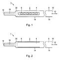
- the test piece 1 according to Fig. 1 is designed to check the penetration properties of a sterilant.
- the obtained when using the specimen 1 Insights can be used in particular for verifying or checking sterilization measures in a steam sterilization process.
- the instruments or materials to be sterilized are introduced into a sterilization chamber, not shown.
- the sterilization chamber is first vented. The venting process can thereby be carried out by flow processes, overpressure or vacuum venting cycles or a combination thereof.
- test piece 1 becomes for example the validation of the sterilization measure used in the sterilization chamber during commissioning or during routine checks during the sterilization process.
- the test specimen 1 comprises a detector 2, which is designed for specific detection that wetting by sterilizing agents has actually taken place.
- the test specimen 1 is designed to emulate the proper wetting and comparatively difficult accessible inner surfaces of instruments or materials suitable.
- the specimen 1 is designed in a so-called hollow body design.
- the detector 2 comprises an indicator 6 arranged in a detector chamber 4, which is designed to be suitable for detecting wetting by the sterilizing agent.
- the gas detector chamber 4 is upstream of a gas collection chamber 8, the end opening 10 is held open.
- the detector 2 as indicated by the double arrow 12, connected via the gas collection chamber 8 on the gas side with the sterilization chamber.
- the test specimen 1 is designed in particular for use in a steam-based sterilization method using a sterilization chamber with particularly high detection accuracy.
- the test specimen 1 together with the instruments or materials to be sterilized in the sterilization chamber brought in.
- the gas collection chamber 8 and the detector chamber 4 are also evacuated.
- the vapor also flows via the end orifice 10 into the gas collecting space 8 and via this into the detector space 4. Any remaining air that could prevent reliable sterilization of the instruments or materials through the formation of air cushions is thereby pressed into the detector chamber 4 via the gas collection chamber 8.
- a concentration of the residual air in the region of the detector 2 so that a complete wetting of the arranged in the detector 2 indicator 6 is omitted with the steam provided as a sterilizing agent.
- the indicator 6, according to the embodiment Fig. 1 occupies a volume of about 120 ul and the detector space 4 thus fills approximately half, could be designed as a sensor for determining a physical measurement value, for example, the temperature or the pressure.
- indicator 6 is a biochemical or chemo indicator.
- a bio-indicator of the indicator 6 is thereby added on its surface with germinable cultures, which are killed in a proper wetting with steam as a sterilant.
- the indicator 6 is thus used in such a way that after sterilization a review is made on germs that are still capable of reproduction. If such are found, inadequate sterilization is inferred.
- the indicator 6 as a chemo indicator this is designed such that it changes its color when wetted with steam as the sterilizing agent under the action of temperature over a predetermined time, so that closed by optical control directly to a continuous wetting can. If not wetted, no or another color change occurs.
- test specimen 1 The executed in hollow body test specimen 1 is designed to ensure particularly reliable test results with high reproducibility and at particularly low cost.
- the test specimen 1 is designed as a disposable product. This design manifests itself inter alia in the fact that with regard to the selection of the materials used, the dimensioning of the individual components and the like, the test specimen 1 is intended for a single use only and not for reuse.
- the detector chamber 4 and / or the gas collection chamber 8 may each be formed of metal.
- the detector chamber 4 and the gas collection chamber 8 are each formed as a piece of tubing.
- the pieces of hose forming the detector chamber 4 and the gas collection chamber 8 can be designed differently from one another, in particular with regard to the choice of material, the dimensioning and / or the flow cross section for the gas.
- the test specimen 1 is designed for a particularly simple design, wherein the detector chamber 4 and the gas collection chamber 8 are formed in the manner of a one-piece design by a common hose body 14.
- the hose body 14 is made of transparent plastic, so that a determination of the test results is made possible by optical evaluation, in particular by observation of the indicator 6.
- test piece 1 A particularly cost-effective production of the test piece 1 according to Fig. 1 is possible by the indicator 6 is introduced into a hose end of the hose body 14 and embedded there, wherein then the corresponding end of the hose 16 is welded. This creates the in Fig. 1 indicated weld 18.
- the housing forming the detector chamber 4 Due to the design of the specimen 1 as a disposable product, a non-destructive removal of the indicator 6 from the detector chamber 4 after verification measure neither provided nor required. Instead, when the indicator 6 is removed, the housing forming the detector chamber 4 is broken up, with the remaining remainder of the test piece 1 subsequently being able to be disposed of. In order to facilitate the removal of the indicator 6, the housing forming the detector chamber 4 has a predetermined breaking point 20, that is to say in particular a suitably predetermined weak point in the wall material.
- the detector chamber 4 may be surrounded by a heat-insulating sheath.
- Fig. 2 an alternative embodiment of the specimen 1 'is shown, in which an indicator 6 is provided on an inner transparent wall of the detector chamber 4 forming piece of tubing applied indicator color.
- an indicator 6 is provided on an inner transparent wall of the detector chamber 4 forming piece of tubing applied indicator color.
- a suspension of a chemo-indicator is then dried.
- execution of the specimen 1 'of the indicator 6 and the detector chamber 4 forming piece of hose of the hose body 14 thus form a mechanically integrated unit in which the indicator 6 is not readily removable from the corresponding piece of hose is.
- a storage of the indicator 6 may be provided together with the tube piece carrying it.
- the test body 1 is designed for a particularly compact design with at the same time particularly high detection sensitivity with regard to the penetration characteristics of the instruments or equipment to be simulated
- the gas collection chamber 8 is designed in several stages, with a first stage 22 immediately adjacent to the detector 2 on the gas side with further Of course, in addition to such a three-stage design, even further stages can be connected in series, or a two-stage design can be provided.
- a according to the construction scheme according to Fig. 3 constructed specimen 1 '"is in Fig. 4 shown nested.
- Its detector 2 comprises an intended for forming the detector chamber 4 and for receiving the indicator 6, by injection molding produced detector housing 28 which is connected to a provided for forming the first stage 22 of the gas collection chamber 8 hose piece 30.
- the first stage 22 of the gas collection chamber 8 is guided in the manner of a nested construction within the second stage 24 of the gas collection chamber 8.
- test body 1 is designed for a particularly high detection sensitivity with a particularly compact design
- first stage 22 in this embodiment is shown in FIG the type of a helix or wound spiral within the second stage 24 enclosing outer housing 32 out.
Abstract
Description
Die Erfindung bezieht sich auf einen Prüfkörper in Hohlkörperbauweise nach Anspruch 1. Sie betrifft weiterhin ein Verfahren zur Herstellung eines derartigen Prüfkörpers. Derartige Prüfkörper sind beispielsweise aus der
Bei aseptischen Anwendungen wie bei Operationen im Krankenhaus ist die Verwendung von sterilen Werkzeugen, Instrumenten oder Materialien zwingend erforderlich. Bei einer dazu notwendigen Sterilisation wird üblicherweise das sterilisierende Medium, wie beispielsweise Dampf, Formaldehyd, Ethylenoxid, Wasserstoffperoxid und/oder Ozon, über die Gasphase auf die Oberfläche des zu sterilisierenden Instruments übertragen, um die totale Abtötung vorhandener Keime zu gewährleisten. Zu diesem Zweck kommen normalerweise Sterilisatoren mit Sterilisationskammern zum Einsatz, in die die zu sterilisierenden Instrumente oder Materialien - im Regelfall verpackt - eingelegt werden. Zur eigentlichen Sterilisation wird die Sterilisationskammer mit gasförmigem Sterilisiermittel - auch als sterilisierendes Agens bezeichnet - geflutet, wobei zuvor die Entfernung der Luftatmosphäre gewährleistet sein muss. Das Sterilisiermittel soll die Oberflächen der zu sterilisierenden Instrumente oder Materialien kontaktieren, so dass die erwünschte Keimabtötung eintritt.For aseptic applications, such as hospital operations, the use of sterile tools, instruments, or materials is imperative. In a sterilization necessary for this purpose, usually the sterilizing medium, such as steam, formaldehyde, ethylene oxide, hydrogen peroxide and / or ozone, transferred via the gas phase to the surface of the instrument to be sterilized to ensure the total killing of existing germs. Sterilizers with sterilization chambers are usually used for this purpose, into which the instruments or materials to be sterilized are inserted, usually packaged. For actual sterilization, the sterilization chamber is flooded with gaseous sterilizing agent - also referred to as a sterilizing agent -, whereby the removal of the air atmosphere must first be ensured. The sterilant should contact the surfaces of the instruments or materials to be sterilized so that the desired germ kill occurs.
Da die vollständige Sterilisation der Güter an allen Stellen nur dann sichergestellt ist, wenn das Sterilisiermittel auch alle inneren Oberflächen erreicht, z. B. poröse Güter oder Hohlkörper ist zu Beginn des Sterilisationsprozesses die Entfernung der im Innern der Güter und im Innern des Sterilisierraums befindlichen Luft durch ein geeignetes Entlüftungsverfahren zu gewährleisten. Anschließend wird die Sterilisationskammer mit dem Sterilisiermittel geflutet, um im Innern der Sterilisationskammer alle Oberflächen der Gerätschaften mit dem Sterilisiermittel zu erreichen. Dies ist nur möglich, wenn die vollständige Penetration des Sterilisiermittels an alle Oberflächen gewährleistet ist.Since the complete sterilization of the goods is ensured at all points only if the sterilant also reaches all internal surfaces, eg. B. porous goods or hollow body is the beginning of the sterilization process, the removal to ensure the air inside the goods and inside the sterilization room by means of a suitable deaeration process. Subsequently, the sterilization chamber is flooded with the sterilizing agent to reach inside the sterilization chamber all surfaces of the equipment with the sterilizing agent. This is only possible if the complete penetration of the sterilant on all surfaces is guaranteed.
Als problematisch bei derartigen Sterilisationsmaßnahmen hat sich jedoch die Komplexität beim strukturellen Aufbau medizinischer Instrumente erwiesen. Gerade bei medizinischen Instrumenten kommen nämlich zunehmend Gerätschaften zum Einsatz, bei denen Röhren oder Schläuche mit relativ großer Länge und vergleichsweise geringem freien Querschnitt verwendet werden, so dass ein zuverlässiges Benetzen des Sterilisiermittels von sämtlichen inneren Oberflächen erschwert ist, wenn sich dort andere Gase befinden. Des Weiteren können Materialien oder Güter mit komplexer Innenoberfläche, wie beispielsweise Textilpakete, zu sterilisieren sein. In derartigen Fällen können eventuell vorhandene Ansammlungen von Restluft oder anderen nicht kondensierbaren Gasen (NKG) den durchgängigen Kontakt der behandlungsbedürftigen Oberfläche ganz oder teilweise verhindern. Die vollständige Sterilisation ist hingegen nur dann sichergestellt, wenn die sich im Innern der Güter befindliche Luft zu Beginn der Sterilisationsmaßnahme vollständig entfernt wird, keine Luft durch Undichtigkeiten während der Vakuumphase eindringt und/oder keine nicht kondensierbare Gase in die Sterilisationskammer mit dem Sterilisiermittel eingetragen werden, damit das Sterilisiermittel an alle behandlungsbedürftigen Oberflächen gelangt.The problem with such sterilization measures, however, has proven to be the complexity in the structural design of medical instruments. Especially in medical instruments are increasingly devices are used, in which tubes or tubes are used with relatively large length and comparatively small free cross-section, so that a reliable wetting of the sterilizing agent of all internal surfaces is difficult if there are other gases. Furthermore, materials or goods having a complex inner surface, such as textile packages, may be to be sterilized. In such cases, any accumulations of residual air or other non-condensable gases (NCGs) may completely or partially prevent the continuous contact of the surface requiring treatment. On the other hand, complete sterilization is only ensured if the air inside the goods is completely removed at the beginning of the sterilization procedure, no air enters through leaks during the vacuum phase and / or no non-condensable gases are introduced into the sterilization chamber with the sterilant. so that the sterilant reaches all surfaces in need of treatment.
Da zudem die Sterilität von Instrumenten vor ihrem Gebrauch nicht direkt geprüft werden kann, sind bei der Inbetriebnahme von Sterilisationsprozessen die Validierung und während des Betriebs des Sterilisationsprozesses Routinekontrollen notwendig. Dazu kommen Detektionssysteme zum Einsatz, die den Sterilisationserfolg nachweisen müssen. Beispielsweise können Chemo-Indikatoren zum Einsatz kommen, die im Falle einer Benetzung ihrer Oberfläche durch das Sterilisiermittel unter Temperatureinwirkung, wie beispielsweise Dampf, ihre Farbe ändern, so dass direkt erkennbar ist, dass an der Stelle des Chemo-Indikators ein Kontakt tatsächlich stattgefunden hat. Alternativ oder zusätzlich können auch Bio-Indikatoren eingesetzt werden, die in Form von Streifen, Suspensionen oder selbst entwickelnden Keimkulturen oder Gemischen verschiedener Keimkulturen zum Einsatz kommen, bei denen nach der Durchführung der Sterilisationsmaßnahme überprüft wird, ob alle Keime vollständig inaktiviert wurden.In addition, since the sterility of instruments can not be tested directly prior to use, routine validation and routine sterilization procedures are required to start sterilization processes. In addition, detection systems are used which must prove the success of sterilization. For example, chemo-indicators can be used which, in the event of wetting of their surface by the sterilant under the influence of temperature, such as steam, change their color, so that it is immediately apparent that a contact actually took place at the site of the chemo indicator. Alternatively or additionally, it is also possible to use bio-indicators which are used in the form of strips, suspensions or self-developing seed cultures or mixtures of different seed cultures, in which it is checked after the sterilization measure has been carried out whether all the germs have been completely inactivated.
Bei der Verwendung derartiger Indikatoren wird überprüft, ob am tatsächlichen Einsatzort des Indikators innerhalb der Sterilisationskammer eine aktive Benetzung der Indikatoroberfläche mit Sterilisiermittel eingetreten ist. Bei der Verwendung dieser Indikatoren ist jedoch ein direkter Nachweis des Sterilisationserfolgs auch an vergleichsweise unzugänglichen Innenoberflächen komplexer Instrumente nicht möglich, da diese an den kritischen Stellen nicht platziert werden können. Daher werden gemeinsam mit den behandlungsbedürftigen Gütern Prüfkörpersysteme mit sterilisiert, durch die der Sterilisationserfolg ermittelt wird. Beispielsweise wurde für die Sterilisationsmaßnahme bei Textilien oder anderen Materialien von Bowie und Dick (
Alternativ können so genannte Prüfkörper oder Prüfkörpersysteme eingesetzt werden. Bei einem derartigen Prüfkörpersystem, wie es beispielsweise in der
Bei diesen bekannten, auch als "Process Challenge Device" (PCD) bezeichneten Prüfkörpersystemen in Hohlkörperbauweise ist ein zum Nachweis eines erfolgten Kontakts durch das Sterilisiermittel geeignet ausgebildeter Detektor gaseingangsseitig mit einem in seiner Länge geeignet gewählten, an seinem Einlassende offen gehaltenen Schlauchmodell verbunden. Das Hohlkörpersystem simuliert dabei das Verhalten ähnlich gestalteter Instrumente, die zur Sterilisation vorgesehen sind, wobei insbesondere bei alternierendem Medienaustausch nach Art eines fraktionierten Vakuums und/oder bei der Kondensation von Dampf eventuell noch vorhandene Restluft oder andere nicht kondensierbare Gase am Schlauchende und somit im Bereich des Detektors aufkonzentriert werden. Der Schlauch wirkt somit als Gassammelraum für Restluft oder andere nicht kondensierbare Gase, wobei der Detektor über diesen Gassammelraum durch Einlegen in die Sterilisationskammer mit dem Sterilisationsraum verbunden ist.In these known, also referred to as "Process Challenge Device" (PCD) specimen systems in hollow body construction is one to prove a successful Contact by the sterilizer suitably trained detector gas inlet side connected to a suitably chosen in its length, held open at its inlet end tube model. The hollow body system simulates the behavior of similarly designed instruments which are intended for sterilization, with residual air or other non-condensable gases remaining at the end of the hose and thus in the region of the still remaining residual air or other non-condensable gases, especially in the case of alternating media exchange in the manner of a fractionated vacuum and / or condensation Detector be concentrated. The tube thus acts as a gas collection chamber for residual air or other non-condensable gases, the detector is connected via this gas collection chamber by placing in the sterilization chamber with the sterilization room.
Falls bei der Verwendung eines derartigen Systems ein Kontakt des am Schlauchende angeordneten Detektors mit Sterilisiermittel festgestellt wird, kann davon ausgegangen werden, dass - gegebenenfalls unter Berücksichtigung eines geeignet gewählten Sicherheitsaufschlags in Bezug auf die Penetrationseigenschaften - in den zu sterilisierenden Instrumenten auch an deren unzugänglichsten Stellen ihrer Innenoberfläche ein Kontakt mit Sterilisiermittel erfolgt sein muss. Ein derartiges Schlauchmodell als Prüfkörper, das als Detektor beispielsweise Bio- oder Chemo-Indikatoren aufnehmen kann, ist auch in der Euronorm EN 867-5 bei der Überprüfung von Sterilisationsprozessen beschrieben. Bei noch komplexeren zu sterilisierenden Gütern können in ihrer Dimensionierung geeignet angepasste Prüfkörper anderer Bauart eingesetzt werden, wie dies beispielsweise in den Euronormen EN 285, EN 14180, EN 1422 oder EN 867-5 beschrieben ist.If, in the use of such a system contact of the arranged at the end of the hose detector with sterilant is determined, it can be assumed that - possibly taking into account a suitably chosen safety impact in terms of penetration properties - in the instruments to be sterilized even at their most inaccessible places Inner surface contact with sterilant must be done. Such a tube model as a test specimen, which can record as a detector, for example, biochemical or chemo-indicators, is also described in the Euronorm EN 867-5 in the review of sterilization processes. For even more complex goods to be sterilized, differently dimensioned test specimens of a different design can be used, as described, for example, in the European standards EN 285, EN 14180, EN 1422 or EN 867-5.
Der Einsatz derartiger Prüfkörper ermöglicht auch, unter bestimmten Randbedingungen physikalische Messmethoden einzusetzen. Beispielsweise ist aus der
Die Verwendung der genannten Hohlkörpersysteme auf der Basis von Prüfkörpern bei der Überprüfung der Penetrationseigenschaften eines Sterilisiermittels in Sterilisationsprozessen ist grundsätzlich vergleichsweise günstig, da durch geeignete Dimensionierung des Gassammelraums und gegebenenfalls des Detektorraums eine Vielzahl von Prüfbedingungen simulierbar oder einstellbar sind. Eine besonders einfach gehaltene, vielseitig einsetzbare Ausgestaltung derartiger Prüfkörper in Hohlkörperbauweise ist daher wünschenswert.The use of said hollow body systems based on test specimens in the examination of the penetration properties of a sterilizing agent in sterilization processes is basically comparatively favorable, since a large number of test conditions can be simulated or adjusted by suitably dimensioning the gas collecting space and optionally the detector space. A particularly simple, versatile design of such specimens in hollow body construction is therefore desirable.
Der Erfindung liegt daher die Aufgabe zugrunde, einen Prüfkörper der oben genannten Art anzugeben, mit dem besonders zuverlässige Prüfungsergebnisse bei einem besonders gering gehaltenen Aufwand erreichbar sind. Des Weiteren soll ein Verfahren zur Herstellung eines derartigen Prüfkörpers angegeben werden.The invention is therefore based on the object of specifying a test specimen of the abovementioned type with which particularly reliable test results can be achieved with a particularly low outlay. Furthermore, a method for producing such a test specimen is to be specified.
Diese Aufgabe wird erfindungsgemäß gelöst durch die Merkmale des Anspruchs 1.This object is achieved by the features of claim 1.
Die Auslegung als Einwegprodukt für den Prüfkörper spezifiziert dabei insbesondere, dass dieser hinsichtlich der Wahl der eingesetzten Materialien und/oder der eingesetzten Herstellungs- oder Bearbeitungsverfahren besonders kostengünstig ausgeführt und lediglich zum einmaligen Gebrauch vorgesehen ist. Im Gegensatz zu Prüfkörpern in Hohlkörperbauweise, die für Mehrfacheinsätze vorgesehen sind und somit notwendigerweise ein wiederverwendbares Aufnahmesystem für den Indikator umfassen, ist der Erfindungsgemäße, als Einwegprodukt ausgelegte Prüfkörper für seine irreversible Zerstörung bei der Entnahme des Indikators ausgelegt.The design as a disposable product for the test specimen specifies in particular that this is particularly cost-effective with regard to the choice of materials used and / or the manufacturing or processing used and provided only for single use. In contrast to test specimens in hollow body construction, which are intended for multiple use and thus necessarily include a reusable recording system for the indicator, the inventive, designed as a disposable test specimen is designed for its irreversible destruction in the removal of the indicator.
Die Erfindung geht von der Überlegung aus, dass die Zuverlässigkeit der Prüfungsergebnisse bei der Verwendung von Prüfkörpern in Hohlkörperbauweise besonders hoch gehalten werden kann, indem denkbare Verschmutzungen, Verunreinigungen und insbesondere auch Reste von Kondensat oder Sterilisiermittel aus einer vorangegangenen Verwendung im Prüfkörpersystem konsequent vermieden werden. Gerade der mehrfache Einsatz eines derartigen Prüfkörpers könnte aber zur Verunreinigung oder Verschmutzung des Gesamtsystems beitragen, so dass vor einer erneuten Verwendung des Prüfkörpersystems eine vergleichsweise aufwendige Endreinigung und Prüfung auf Sauberkeit und Dichtheit notwendig ist. Demgegenüber gewährleistet ein lediglich einmaliger Einsatz eines derartigen Prüfkörpersystems besonders hohen Schutz vor den oben genannten Veränderungen. Um zudem noch die flexible Anpassung an individuell vorgebbare Prüfbedingungen einerseits sowie eine besonders kostengünstige Ausführung des Prüfkörpers andererseits zu ermöglichen, ist der Prüfkörper im Hinblick auf die konstruktive Auslegung seiner Komponenten und auch die Wahl der eingesetzten Materialien konsequent als Einwegprodukt ausgelegt.The invention is based on the consideration that the reliability of the test results in the use of test specimens in hollow body construction can be kept very high by conceivable contamination, impurities and in particular residues of condensate or sterilant from a previous use in Prüfkörpersystem are consistently avoided. Especially the multiple use of such a specimen could contribute to the contamination or contamination of the entire system, so that before reuse of the Prüfkörpersystems a comparatively complicated cleaning and test for cleanliness and tightness is necessary. In contrast, ensures only a single use of such Prüfkörpersystems particularly high protection against the above changes. In addition, to allow the flexible adaptation to individually specifiable test conditions on the one hand and a particularly cost-effective design of the test body on the other hand, the test specimen is consistently designed as a disposable product with regard to the structural design of its components and the choice of materials.
Eine besonders einfache und kostengünstige Herstellung ist dabei erreicht, indem der verwendete Indikator an einem Schlauchende eingebettet und das Schlauchende zur Bildung des Detektorraums anschließend verschweißt wird.A particularly simple and cost-effective production is achieved by the indicator used is embedded at a hose end and the hose end is then welded to form the detector chamber.
Der Schlauch kann dabei zweckmäßigerweise für eine optische Auswertung der Prüfergebnisse in vorteilhafter Ausgestaltung aus transparentem Kunststoff gebildet sein.The tube can be suitably formed for an optical evaluation of the test results in an advantageous embodiment of transparent plastic.
Um eine besonders flexible und zuverlässige Vorgabe selektiver Prüfbedingungen zu ermöglichen, ist der Gassammelraum vorteilhafterweise mit einer Wärme isolierenden Ummantelung versehen.In order to allow a particularly flexible and reliable specification of selective test conditions, the gas collecting space is advantageously provided with a heat-insulating sheath.
Eine besonders kompakte Bauweise ist erreichbar, indem der Gassammelraum vorzugsweise in der Art einer Spirale ausgebildet ist, indem vorzugsweise ein Plastikteil tiefgezogen oder gespritzt wird. Insbesondere bei der Verwendung eines Schlauchs zur Bildung des Detektorraums und insbesondere des Gassammelraums kann der Schlauch dabei zu einer Helix gerollt und mit Kabelbindern oder sonstigen Verbindungsteilen zusammengehalten sein.A particularly compact design is achievable in that the gas collecting space is preferably designed in the manner of a spiral, preferably by deep drawing or spraying a plastic part. In particular, when using a hose for forming the detector chamber and in particular the gas collecting space, the hose can be rolled into a helix and held together with cable ties or other connecting parts.
Um eine besonders einfache Entnahme des Indikators nach durchgeführter Prüfung zu ermöglichen, ist der Detektorraum vorteilhafterweise mit einer Sollbruchstelle versehen. Gerade durch die Zerstörung des Detektorraums bei der Entnahme des Indikators ist dabei gewährleistet, dass im Sinne des bestimmungsgemäßen Gebrauchs des Prüfkörpers eine lediglich einmalige Verwendung eingehalten wird.In order to enable a particularly simple removal of the indicator after carrying out the test, the detector space is advantageously provided with a predetermined breaking point. Just by the destruction of the detector chamber during the removal of the indicator is thereby ensured that in the sense of the intended use of the test specimen a single use is adhered to.
Eine besonders hohe Nachweisempfindlichkeit des Prüfkörpers ist erreichbar, indem der Gassammelraum in besonders vorteilhafter Ausgestaltung mehrstufig ausgeführt ist, wobei der Querschnitt und/oder das Volumen jeder Stufe zwischen benachbarten Stufen in Richtung zum Detektorraum hin abnehmen. Wie sich nämlich überraschenderweise herausgestellt hat, ermöglicht eine derartige Auslegung die selektive Aufkonzentration noch vorhandener Restluft oder Restgase im Gassammelraum in unmittelbarer Nachbarschaft zum Detektorraum, so dass eine besonders hohe Verstärkung der Nachweisempfindlichkeit erreichbar ist.A particularly high detection sensitivity of the test specimen is achievable in that the gas collecting space is designed to be multi-stage in a particularly advantageous embodiment, the cross section and / or the volume of each stage decreasing between adjacent stages in the direction of the detector chamber. As has surprisingly been found, such a design allows the selective concentration of residual air or residual gases remaining in the gas collection chamber in the immediate vicinity of the detector chamber, so that a particularly high amplification of the detection sensitivity can be achieved.
Als Indikator kann ein so genannter physikalischer Indikator, also ein System zur Ermittlung physikalischer Kennwerte wie beispielsweise ein Feuchtigkeits-, Temperatur-, Druck- und/oder Ultraschallsensor, der sich im Detektorraum befindet, zum Einsatz kommen, der bedarfsweise auch als so genannter Daten-Logger für eine drahtlose Übermittlung der aufgenommenen Daten ausgestaltet sein kann. Auch können beispielsweise Festkörper, wie z. B. Salze, eingesetzt sein, die sich bei Anwesenheit des Sterilisiermittels physikalisch verändern, also beispielsweise ihren Schmelzpunkt oder ihre Farbe ändern. Des Weiteren kann als Indikator ein so genannter Chemo-Indikator, der bei Kontakt mit dem eingesetzten Sterilisiermittel seine Farbe ändert, oder ein Bio-Indikator, beispielsweise in Form von Indikatorstreifen und/oder selbstentwickelnden Bio-Indikatoren, vorgesehen sein.An indicator may be a so-called physical indicator, ie a system for determining physical characteristics, such as a humidity, temperature, pressure and / or ultrasound sensor, which is located in the detector chamber, which may also be used as so-called data Logger for a wireless transmission of the recorded data can be configured. Also, for example, solids, such. As salts, be used, which physically change in the presence of the sterilant, so for example, change their melting point or their color. Furthermore, a so-called chemo-indicator, which changes color upon contact with the sterilant used, or a bio-indicator, for example in the form of indicator strips and / or self-developing bio-indicators, may be provided as an indicator.
Eine konsequente Ausnutzung der Auslegung des Prüfkörpers als Einwegprodukt hinsichtlich gering gehaltenem Herstellungsaufwand ist aber erreichbar, indem als Indikator in besonders vorteilhafter Ausgestaltung auf eine transparente Innenwand des den Detektorraum bildenden Gehäuses aufgebrachte Indikatorfarbe vorgesehen ist. Bei dieser Ausführung ist der Indikator mechanisch fest mit Teilen des den Detektorraum bildenden Gehäuses integriert, so dass gesonderte Stützoder Tragstrukturen für den Indikator als solchen entfallen können. Aufgrund der Auslegung des Prüfkörpers als Einwegprodukt kann nach dessen Einsatz der Indikator gemeinsam mit den ihn tragenden Gehäuseteilen des Detektorraums entnommen und geeignet begutachtet und eventuell archiviert werden.A consistent exploitation of the design of the test specimen as a disposable product with respect to low production costs but can be achieved by an indicator indicator in a particularly advantageous embodiment on a transparent inner wall of the detector chamber forming housing applied indicator color is provided. In this embodiment, the indicator is mechanically firmly integrated with parts of the housing forming the detector space, so that separate support or support structures for the indicator can be omitted as such. Due to the design of the test specimen as a disposable product, the indicator can be removed together with the housing parts of the detector chamber carrying it after its use and suitably inspected and possibly archived.
Bezüglich des Verfahrens zur Herstellung eines Prüfkörpers der beschriebenen Art wird die genannte Aufgabe gelöst, indem auf die Innenwand eines zur Bereitstellung eines Detektorraums vorgesehenen Schlauchstücks eine Suspension eines Chemo- oder Bio-Indikators aufgebracht und anschließend getrocknet wird. Bereits herstellungsbedingt ist der dabei erhältliche Prüfkörper als Einwegprodukt ausgelegt, wobei auf diese Weise eine besonders einfach gehaltene und somit kostengünstige Herstellung des Prüfkörpers gewährleistet ist.With regard to the method for producing a test specimen of the type described, the stated object is achieved by applying to the inner wall of a tube piece provided for providing a detector space a suspension of a chemo or bio-indicator and then dried. Already production reasons, the test specimen available is designed as a disposable product, in this way a particularly simple and thus cost-effective production of the specimen is guaranteed.
Die mit der Erfindung erzielten Vorteile bestehen insbesondere darin, dass durch die konsequente Auslegung gerade eines in Hohlkörperbauweise ausgeführten Prüfkörpers als Einwegprodukt die Beeinträchtigung der Prüfungsergebnisse durch Rückstände des Sterilisiermittels aus vorangegangenen Prozessen, Verunreinigungen oder Verschmutzungen in besonderem Maße gering gehalten werden können. Somit ist eine besonders hohe Zuverlässigkeit und Reproduzierbarkeit bei der Ermittlung der Überprüfungsergebnisse erreichbar. Durch die Ausführung des Prüfkörpersystems in Hohlkörperbauweise als Einwegprodukt können je nach Bedarf und Konstruktion besonders hohe Anforderungen an die Penetrationseigenschaften eines Sterilisationsprozesses gestellt werden, so dass reproduzierbar sichergestellt werden kann, dass die zunehmend eingesetzten Hohlkörperinstrumente, beispielsweise für minimal-invasiv-chirurgische Anwendungen und/oder lange Schläuche zum Absaugen und Betreiben von pneumatischen Bohrmaschinen, mit besonders hoher Zuverlässigkeit sterilisiert werden. Gerade durch die Ausgestaltung eines in Hohlkörperbauweise ausgeführten Prüfkörpers als Einwegprodukt kann für derartig komplexe hohle Instrumente und Schläuche eine besonders hohe Sterilisationssicherheit gewährleistet werden.The advantages achieved by the invention are in particular that the impairment of the test results due to residues of the sterilizing agent from previous processes, impurities or contamination can be kept to a particularly low level by the consistent design just a running in hollow body test specimen as a disposable product. Thus, a particularly high reliability and reproducibility in the determination of the inspection results can be achieved. By executing the test body system in hollow body construction as a disposable product can be made depending on the needs and design particularly high demands on the penetration properties of a sterilization process, so that it can be reproducibly ensured that the increasingly used hollow body instruments, for example, for minimally invasive surgical applications and / or long hoses for the suction and operation of pneumatic drills are sterilized with particularly high reliability. Especially by the design of a running in hollow body construction test specimen as a disposable product can be guaranteed for such complex hollow instruments and tubes a particularly high sterilization security.
Ein Ausführungsbeispiel der Erfindung wird anhand einer Zeichnung näher erläutert. Darin zeigen:
- Fig. 1, 2
- jeweils schematisch einen Prüfkörper in Hohlkörperbauweise,
- Fig. 3
- ein Aufbauschema für einen Prüfkörper, und
- Fig. 4
- einen Prüfkörper zur Überprüfung der Penetrationseigenschaften eines Sterilisiermittels.
- Fig. 1, 2
- each schematically a test specimen in hollow body construction,
- Fig. 3
- a construction scheme for a test specimen, and
- Fig. 4
- a test specimen for checking the penetration properties of a sterilizing agent.
Gleiche Teile sind in allen Figuren mit den selben Bezugszeichen versehen.The same parts are provided in all figures with the same reference numerals.
Der Prüfkörper 1 gemäß
Um bei einem derartigen, auf fraktioniertem Vakuum beruhenden Entlüftungsverfahren nachweisen zu können, dass bei den zu sterilisierenden Instrumenten und Materialien auch tatsächlich sämtliche inneren Oberflächen mit Sterilisiermittel benetzt worden sind und somit die erforderliche vollständige Penetration stattgefunden hat, wird der Prüfkörper 1 beispielsweise zur Validierung der Sterilisationsmaßnahme bei ihrer Inbetriebnahme oder bei Routinekontrollen während des Sterilisationsprozesses mit in der Sterilisationskammer eingesetzt. Der Prüfkörper 1 umfasst einen Detektor 2, der für den gezielten Nachweis ausgelegt ist, dass eine Benetzung durch Sterilisiermittel tatsächlich stattgefunden hat.In order to be able to demonstrate, in such a vented vacuum-based venting method, that in the instruments and materials to be sterilized, in fact all inner surfaces have been wetted with sterilant and thus the required complete penetration has taken place, the test piece 1 becomes for example the validation of the sterilization measure used in the sterilization chamber during commissioning or during routine checks during the sterilization process. The test specimen 1 comprises a
Der Prüfkörper 1 ist dafür ausgebildet, die ordnungsgemäße Benetzung auch vergleichsweise schwer zugänglicher innerer Oberflächen von Instrumenten oder Materialien geeignet nachzubilden. Dazu ist der Prüfkörper 1 in so genannter Hohlkörperbauweise ausgeführt. In dieser Hohlkörperbauweise umfasst der Detektor 2 einen in einem Detektorraum 4 angeordneten Indikator 6, der zum Nachweis einer Benetzung durch das Sterilisiermittel geeignet ausgeführt ist. Dem Detektorraum 4 ist gasseitig ein Gassammelraum 8 vorgeschaltet, dessen Endmündung 10 offen gehalten ist. Somit ist der Detektor 2, wie durch den Doppelpfeil 12 angedeutet, über den Gassammelraum 8 gasseitig mit der Sterilisationskammer verbunden.The test specimen 1 is designed to emulate the proper wetting and comparatively difficult accessible inner surfaces of instruments or materials suitable. For this purpose, the specimen 1 is designed in a so-called hollow body design. In this hollow body construction, the
Der Prüfkörper 1 ist insbesondere für eine Anwendung bei einem dampfbasierten Sterilisationsverfahren unter Verwendung einer Sterilisationskammer mit besonders hoher Nachweisgenauigkeit ausgelegt. Dazu wird der Prüfkörper 1 gemeinsam mit den zu sterilisierenden Instrumenten oder Materialien in die Sterilisationskammer eingebracht. Im ersten Bearbeitungsschritt, in dem die Sterilisationskammer evakuiert wird, werden auch der Gassammelraum 8 sowie der Detektorraum 4 evakuiert. Anschließend, wenn die Sterilisationskammer mit Dampf als Sterilisiermittel befüllt wird, strömt der Dampf über die Endmündung 10 auch in den Gassammelraum 8 und über diesen in den Detektorraum 4 ein. Eventuell noch vorhandene Restluft, die durch die Bildung von Luftpolstern eine zuverlässige Sterilisation der Instrumente oder Materialien verhindern könnte, wird dabei über den Gassammelraum 8 in den Detektorraum 4 hineingedrückt. Somit erfolgt eine Aufkonzentration der Restluft im Bereich des Detektors 2, so dass eine vollständige Benetzung des im Detektor 2 angeordneten Indikators 6 mit dem als Sterilisiermittel vorgesehen Dampf unterbleibt.The test specimen 1 is designed in particular for use in a steam-based sterilization method using a sterilization chamber with particularly high detection accuracy. For this purpose, the test specimen 1 together with the instruments or materials to be sterilized in the sterilization chamber brought in. In the first processing step in which the sterilization chamber is evacuated, the
In sukzessiv erfolgenden weiteren Verfahrensschritten, bei denen in der Art eines fraktionierten Vakuums erneut ein Unterdruck in der Sterilisationskammer erzeugt und diese anschließend mit Dampf als Sterilisiermittel befüllt wird, erfolgt ein sukzessiv zunehmender Austrag der Restluft aus der Sterilisationskammer. Dadurch erfolgt eine zunehmend zuverlässige und durchgängige Benetzung sämtlicher inneren Oberflächen der Instrumente, die analog auch zu einer zunehmend besseren Benetzung der Innenoberfläche des Gassammelraums 8 führt. Falls eine ausreichende Penetration des Sterilisiermittels in den Prüfkörper 1 hinein erfolgt, kann eine durchgängige Benetzung auch des Indikators 6 festgestellt werden. Wenn dies eintritt, wird die Sterilisationsmaßnahme als erfolgreich angesehen.In successive further process steps, in which in the manner of a fractionated vacuum again creates a negative pressure in the sterilization chamber and this is then filled with steam as a sterilant, there is a successively increasing discharge of the residual air from the sterilization chamber. This results in an increasingly reliable and continuous wetting of all inner surfaces of the instruments, which also leads to an increasingly better wetting of the inner surface of the
Der Indikator 6, der im Ausführungsbeispiel nach
Bei einer Ausgestaltung des Indikators 6 als Chemo-Indikator ist dieser derart ausgebildet, dass er bei einer Benetzung seiner Oberfläche mit Dampf als Sterilisiermittel unter Einwirkung von Temperatur über eine vorgegebene Zeit seine Farbe ändert, so dass durch optische Kontrolle direkt auf eine durchgängige Benetzung geschlossen werden kann. Bei Nicht-Benetzung erfolgt kein oder ein anderer Farbumschlag.In one embodiment of the
Der in Hohlkörperbauweise ausgeführte Prüfkörper 1 ist zur Sicherstellung besonders zuverlässiger Prüfungsergebnisse mit hoher Reproduzierbarkeit und bei besonders gering gehaltenem Aufwand ausgelegt. Dazu ist der Prüfkörper 1 als Einwegprodukt ausgelegt. Diese Auslegung manifestiert sich unter anderem darin, dass hinsichtlich der Auswahl der eingesetzten Materialien, der Dimensionierung der einzelnen Komponenten und dergleichen der Prüfkörper 1 für einen lediglich einmaligen Gebrauch und nicht für eine Wiederverwendung vorgesehen ist.The executed in hollow body test specimen 1 is designed to ensure particularly reliable test results with high reproducibility and at particularly low cost. For this purpose, the test specimen 1 is designed as a disposable product. This design manifests itself inter alia in the fact that with regard to the selection of the materials used, the dimensioning of the individual components and the like, the test specimen 1 is intended for a single use only and not for reuse.
Der Detektorraum 4 und/oder der Gassammelraum 8 können jeweils aus Metall gebildet sein. Im Ausführungsbeispiel nach
Eine besonders kostengünstige Herstellung des Prüfkörpers 1 nach
Aufgrund der Ausführung des Prüfkörpers 1 als Einwegprodukt ist eine zerstörungsfreie Entnahme des Indikators 6 aus dem Detektorraum 4 nach erfolgter Verifikationsmaßnahme weder vorgesehen noch erforderlich. Stattdessen wird bei der Entnahme des Indikators 6 das den Detektorraum 4 bildende Gehäuse aufgebrochen, wobei anschließend der verbleibende Rest des Prüfkörpers 1 einer Entsorgung zugeführt werden kann. Um die Entnahme des Indikators 6 zu erleichtern, weist das den Detektorraum 4 bildende Gehäuse eine Sollbruchstelle 20, also insbesondere eine geeignet vorgegebene Schwachstelle im Wandmaterial, auf.Due to the design of the specimen 1 as a disposable product, a non-destructive removal of the
Zur Erhöhung der Nachweisgenauigkeit kann der Gassammelraum 8 und ggf. auch der Detektorraum 4 von einer Wärme isolierenden Ummantelung umgeben sein.To increase the accuracy of detection of the
In
Im Ausführungsbeispiel nach
Durch die mehrstufige Ausgestaltung des Gassammelraums 8 mittels der gasseitigen Vorschaltung der zweiten und dritten Stufe 24, 26 vor die erste Stufe 22, und durch eine geeignet gewählte Dimensionierung der Stufen 22, 24, 26 ist beim Prüfkörper 1" sichergestellt, dass die für den Prozess schädliche Restluft im unmittelbaren Bereich der ersten Stufe 22 gezielt aufkonzentriert wird. Diese Aufkonzentration erfolgt insbesondere durch die gasseitig vorgelagerten Stufen 24, 26, die als Kondensationszone für das Sterilisiermittel dienen und eine selektive lokale Auskondensation des Sterilisiermittels unmittelbar vor dem Eintrittsbereich in die erste Stufe 22 bewirken. Durch die damit erreichte Aufkonzentration der Restluft oder anderer nicht kondensierbarer Gase erfolgt ein nachhaltiger und besonders zuverlässiger Nachweis der Restluft oder andere nicht kondensierbare Gase, so dass der Prüfkörper 1" mit einer besonders hohen Nachweisgenauigkeit betrieben werden kann. Um dies zu gewährleisten, nehmen Strömungsquerschnitt und Volumen der Stufen 24, 26 zwischen den benachbarten Stufen 24, 26 in Strömungsrichtung zum Detektor 2 hin signifikant ab.Due to the multi-stage design of the
Ein nach dem Aufbauschema gemäß
- 1, 1', 1 ", 1"'1, 1 ', 1 ", 1"'
- Prüfkörperspecimen
- 22
- Detektordetector
- 44
- Detektorraumdetector chamber
- 66
- Indikatorindicator
- 88th
- GassammelraumGas collection space
- 1010
- Endmündungend opening
- 1212
- Doppelpfeildouble arrow
- 1414
- Schlauchkörpertube body
- 1616
- Schlauchendehose end
- 1818
- SchweißnahtWeld
- 2020
- SollbruchstelleBreaking point
- 2121
- Deckelcover
- 22,24,2622,24,26
- Stufenstages
- 2828
- Detektorgehäusedetector housing
- 3030
- Schlauchstückhose Connector
- 3232
- Außengehäuseouter casing
Claims (9)
- Test device (1, 1', 1'', 1''') in hollow construction, especially to test the penetration characteristics of a sterilization agent in a sterilization process, with a detector volume (4) provided with an indicator (6) and a gas-collection-volume (8) consisting of a plastic tube, which is connected to the detector volume (4) at the gas side, that is designed as disposable product so that it is irreversibly destroyed after extraction of the indicator (6), whereas the indicator (6) is embedded at one of the tube ends ad the tube end is welded to build the detector volume (4).
- Test device (1, 1', 1 ", 1''') according to claim 1, whose gas-collection-volume is winded as a helix.
- Test device (1, 1', 1'', 1''') according to claim 1 or 2, whose case building the detector volume (4) has a predetermined breaking point (2).
- Test device (1, 1', 1", 1''') according to one of the claims 1 to 3, whose gas-collection-volume (8) is multi-stage designed, whereas the cross-section and/or the volume of each stage (22, 24, 26) decreases between the adjacent stages (22, 24, 26) in direction of the detector volume (4).
- Test device (1, 1', 1", 1''') according to one of the claims 1 to 4, whose gas-collection-volume (8) is provided with a heat insulating cover.
- Test device (1, 1', 1", 1''') according to one of the claims 1 to 5 with an indicator colour as detector at the inside of a transparent wall of the case building the detector volume.
- Test device (1, 1', 1'', 1''') according to one of the claims 1 to 5 with a chemical, biological and/or physical indicator as detector.
- Test device (1, 1', 1", 1'") according to one of the claims 1 to 7, with a tube of transparent plastic material.
- Procedure to produce a test device (1, 1', 1", 1''') according to one of the claims 1 to 8, where at the inner wall of a piece of tube, which is provided to function as a detector volume (4), a suspension of a chemical or biological indicator is applied and dried afterwards.
Priority Applications (4)
| Application Number | Priority Date | Filing Date | Title |
|---|---|---|---|
| AT03028828T ATE387223T1 (en) | 2003-12-15 | 2003-12-15 | TEST SPECIMEN FOR CHECKING THE PENETRATION PROPERTIES OF A STERILIZING AGENT IN STERILIZATION PROCESSES |
| EP03028828A EP1550467B1 (en) | 2003-12-15 | 2003-12-15 | Test device for checking the permeation properties of a sterilising agent in sterilisation processes |
| DE50309274T DE50309274D1 (en) | 2003-12-15 | 2003-12-15 | Test specimen for checking the penetration properties of a sterilizing agent in sterilization processes |
| PCT/EP2004/014289 WO2005056061A1 (en) | 2003-12-15 | 2004-12-15 | Test piece for verifying the penetration characteristics of a sterilizing agent in sterilization processes |
Applications Claiming Priority (1)
| Application Number | Priority Date | Filing Date | Title |
|---|---|---|---|
| EP03028828A EP1550467B1 (en) | 2003-12-15 | 2003-12-15 | Test device for checking the permeation properties of a sterilising agent in sterilisation processes |
Publications (2)
| Publication Number | Publication Date |
|---|---|
| EP1550467A1 EP1550467A1 (en) | 2005-07-06 |
| EP1550467B1 true EP1550467B1 (en) | 2008-02-27 |
Family
ID=34560163
Family Applications (1)
| Application Number | Title | Priority Date | Filing Date |
|---|---|---|---|
| EP03028828A Expired - Lifetime EP1550467B1 (en) | 2003-12-15 | 2003-12-15 | Test device for checking the permeation properties of a sterilising agent in sterilisation processes |
Country Status (4)
| Country | Link |
|---|---|
| EP (1) | EP1550467B1 (en) |
| AT (1) | ATE387223T1 (en) |
| DE (1) | DE50309274D1 (en) |
| WO (1) | WO2005056061A1 (en) |
Families Citing this family (4)
| Publication number | Priority date | Publication date | Assignee | Title |
|---|---|---|---|---|
| WO2009137442A1 (en) | 2008-05-05 | 2009-11-12 | 3M Innovative Properties Company | Sterilization process challenge device and method |
| EP2350307B1 (en) | 2008-11-06 | 2016-07-27 | 3M Innovative Properties Company | Process challenge device and methods |
| NL2018932B1 (en) * | 2017-05-17 | 2018-11-28 | Solidtoo B V | Monitoring of steam quality during sterilization |
| GB2567901A (en) * | 2017-10-31 | 2019-05-01 | De Sternberg Stojalowski Pawel | Process challenge device for evaluation of contamination forming and removal processes inside of hollow channels and methods for contamination evaluation |
Family Cites Families (4)
| Publication number | Priority date | Publication date | Assignee | Title |
|---|---|---|---|---|
| US4914034A (en) * | 1987-05-15 | 1990-04-03 | American Sterilizer Company | Disposable biological indicator test pack for monitoring steam and ethylene oxide sterilization cycles |
| DE9104824U1 (en) * | 1991-04-19 | 1991-08-22 | Broemeda-Klinikbedarf I. Broemser Gmbh, 6238 Hofheim, De | |
| EP0628814A1 (en) * | 1993-06-14 | 1994-12-14 | Ulrich Dr. Kaiser | Indicator test system for monitoring air removal and/or sterilisation of full loads in steam sterilisers |
| DE19724158A1 (en) * | 1997-06-07 | 1998-12-10 | Secundus Medizinische Kontroll | Sterilisation test assembly comprises extended inlet tube wound around outer face |
-
2003
- 2003-12-15 DE DE50309274T patent/DE50309274D1/en not_active Expired - Lifetime
- 2003-12-15 EP EP03028828A patent/EP1550467B1/en not_active Expired - Lifetime
- 2003-12-15 AT AT03028828T patent/ATE387223T1/en not_active IP Right Cessation
-
2004
- 2004-12-15 WO PCT/EP2004/014289 patent/WO2005056061A1/en active Application Filing
Also Published As
| Publication number | Publication date |
|---|---|
| ATE387223T1 (en) | 2008-03-15 |
| EP1550467A1 (en) | 2005-07-06 |
| WO2005056061A1 (en) | 2005-06-23 |
| DE50309274D1 (en) | 2008-04-10 |
Similar Documents
| Publication | Publication Date | Title |
|---|---|---|
| EP1468701B1 (en) | Challenge device, especially for testing the penetration properties of a sterilant in sterilising processes | |
| DE69721499T2 (en) | SYSTEM AND METHOD FOR REAL-TIME MONITORING AND CONTROL OF TREATMENT STERLIZATION AND PARAMETRIC RELEASE | |
| EP2216648B1 (en) | Cleaning indicator and test body for testing cleaning processes | |
| EP2557417B1 (en) | Replacement fitting | |
| US20090304548A1 (en) | Sterilizer test device | |
| DE69723521T2 (en) | Method and device for detecting trapped water in a vacuum chamber | |
| EP1827510B1 (en) | Method and device for decontaminating articles, especially for detoxicating or disinfecting temperature-sensitive small military devices | |
| EP2247926A2 (en) | Method for calibrating a sensor within a chamber, sensor, disposable device, and treatment device having such a sensor | |
| EP2770938A2 (en) | Sterile medical container and method for determining the sterilization status of a sterile medical container | |
| WO2011066901A1 (en) | Sensor protective device | |
| EP1850102A1 (en) | Measuring device for checking the effectiveness of a steam sterilisation process | |
| EP0628814A1 (en) | Indicator test system for monitoring air removal and/or sterilisation of full loads in steam sterilisers | |
| EP1550467B1 (en) | Test device for checking the permeation properties of a sterilising agent in sterilisation processes | |
| EP1000629B1 (en) | Steriliser with a sensor and method for monitoring the sensor | |
| DE19838678C2 (en) | Steam sterilizer | |
| DE19944847C1 (en) | Sterilization test device | |
| EP1610827B1 (en) | Sterilization testing device | |
| DE112018008133T5 (en) | Conical indicator for use in process test pieces | |
| DE10220668A1 (en) | Incubation chamber has gas sensor with emitter and detectors co-located in thermally-protected chamber with side gas apertures | |
| DE202016005870U1 (en) | Air and leak detector for steam sterilizers | |
| DE102013219101A1 (en) | Apparatus and method for calibrating a gas sensor | |
| EP3485915A1 (en) | Device and method for detecting a successful thermal disinfection or sterilization | |
| EP3485916A1 (en) | Device and method for detecting a successful thermal disinfection or sterilization | |
| EP1333867B1 (en) | Measuring device for detecting temperature dependent measured values | |
| DE19724158A1 (en) | Sterilisation test assembly comprises extended inlet tube wound around outer face |
Legal Events
| Date | Code | Title | Description |
|---|---|---|---|
| PUAI | Public reference made under article 153(3) epc to a published international application that has entered the european phase |
Free format text: ORIGINAL CODE: 0009012 |
|
| 17P | Request for examination filed |
Effective date: 20050117 |
|
| AK | Designated contracting states |
Kind code of ref document: A1 Designated state(s): AT BE BG CH CY CZ DE DK EE ES FI FR GB GR HU IE IT LI LU MC NL PT RO SE SI SK TR |
|
| AX | Request for extension of the european patent |
Extension state: AL LT LV MK |
|
| AKX | Designation fees paid |
Designated state(s): AT BE BG CH CY CZ DE DK EE ES FI FR GB GR HU IE IT LI LU MC NL PT RO SE SI SK TR |
|
| GRAP | Despatch of communication of intention to grant a patent |
Free format text: ORIGINAL CODE: EPIDOSNIGR1 |
|
| GRAS | Grant fee paid |
Free format text: ORIGINAL CODE: EPIDOSNIGR3 |
|
| GRAA | (expected) grant |
Free format text: ORIGINAL CODE: 0009210 |
|
| AK | Designated contracting states |
Kind code of ref document: B1 Designated state(s): AT BE BG CH CY CZ DE DK EE ES FI FR GB GR HU IE IT LI LU MC NL PT RO SE SI SK TR |
|
| REG | Reference to a national code |
Ref country code: GB Ref legal event code: FG4D Free format text: NOT ENGLISH |
|
| REG | Reference to a national code |
Ref country code: CH Ref legal event code: EP |
|
| REG | Reference to a national code |
Ref country code: IE Ref legal event code: FG4D Free format text: LANGUAGE OF EP DOCUMENT: GERMAN |
|
| REF | Corresponds to: |
Ref document number: 50309274 Country of ref document: DE Date of ref document: 20080410 Kind code of ref document: P |
|
| PG25 | Lapsed in a contracting state [announced via postgrant information from national office to epo] |
Ref country code: ES Free format text: LAPSE BECAUSE OF FAILURE TO SUBMIT A TRANSLATION OF THE DESCRIPTION OR TO PAY THE FEE WITHIN THE PRESCRIBED TIME-LIMIT Effective date: 20080607 Ref country code: FI Free format text: LAPSE BECAUSE OF FAILURE TO SUBMIT A TRANSLATION OF THE DESCRIPTION OR TO PAY THE FEE WITHIN THE PRESCRIBED TIME-LIMIT Effective date: 20080227 |
|
| NLV1 | Nl: lapsed or annulled due to failure to fulfill the requirements of art. 29p and 29m of the patents act | ||
| PG25 | Lapsed in a contracting state [announced via postgrant information from national office to epo] |
Ref country code: SI Free format text: LAPSE BECAUSE OF FAILURE TO SUBMIT A TRANSLATION OF THE DESCRIPTION OR TO PAY THE FEE WITHIN THE PRESCRIBED TIME-LIMIT Effective date: 20080227 |
|
| REG | Reference to a national code |
Ref country code: IE Ref legal event code: FD4D |
|
| PG25 | Lapsed in a contracting state [announced via postgrant information from national office to epo] |
Ref country code: SK Free format text: LAPSE BECAUSE OF FAILURE TO SUBMIT A TRANSLATION OF THE DESCRIPTION OR TO PAY THE FEE WITHIN THE PRESCRIBED TIME-LIMIT Effective date: 20080227 Ref country code: SE Free format text: LAPSE BECAUSE OF FAILURE TO SUBMIT A TRANSLATION OF THE DESCRIPTION OR TO PAY THE FEE WITHIN THE PRESCRIBED TIME-LIMIT Effective date: 20080527 Ref country code: PT Free format text: LAPSE BECAUSE OF FAILURE TO SUBMIT A TRANSLATION OF THE DESCRIPTION OR TO PAY THE FEE WITHIN THE PRESCRIBED TIME-LIMIT Effective date: 20080721 Ref country code: NL Free format text: LAPSE BECAUSE OF FAILURE TO SUBMIT A TRANSLATION OF THE DESCRIPTION OR TO PAY THE FEE WITHIN THE PRESCRIBED TIME-LIMIT Effective date: 20080227 Ref country code: IE Free format text: LAPSE BECAUSE OF FAILURE TO SUBMIT A TRANSLATION OF THE DESCRIPTION OR TO PAY THE FEE WITHIN THE PRESCRIBED TIME-LIMIT Effective date: 20080227 Ref country code: DK Free format text: LAPSE BECAUSE OF FAILURE TO SUBMIT A TRANSLATION OF THE DESCRIPTION OR TO PAY THE FEE WITHIN THE PRESCRIBED TIME-LIMIT Effective date: 20080227 Ref country code: CZ Free format text: LAPSE BECAUSE OF FAILURE TO SUBMIT A TRANSLATION OF THE DESCRIPTION OR TO PAY THE FEE WITHIN THE PRESCRIBED TIME-LIMIT Effective date: 20080227 |
|
| PG25 | Lapsed in a contracting state [announced via postgrant information from national office to epo] |
Ref country code: RO Free format text: LAPSE BECAUSE OF FAILURE TO SUBMIT A TRANSLATION OF THE DESCRIPTION OR TO PAY THE FEE WITHIN THE PRESCRIBED TIME-LIMIT Effective date: 20080227 |
|
| EN | Fr: translation not filed | ||
| PLBE | No opposition filed within time limit |
Free format text: ORIGINAL CODE: 0009261 |
|
| STAA | Information on the status of an ep patent application or granted ep patent |
Free format text: STATUS: NO OPPOSITION FILED WITHIN TIME LIMIT |
|
| 26N | No opposition filed |
Effective date: 20081128 |
|
| PGFP | Annual fee paid to national office [announced via postgrant information from national office to epo] |
Ref country code: IT Payment date: 20081223 Year of fee payment: 6 |
|
| PG25 | Lapsed in a contracting state [announced via postgrant information from national office to epo] |
Ref country code: FR Free format text: LAPSE BECAUSE OF FAILURE TO SUBMIT A TRANSLATION OF THE DESCRIPTION OR TO PAY THE FEE WITHIN THE PRESCRIBED TIME-LIMIT Effective date: 20081219 Ref country code: BG Free format text: LAPSE BECAUSE OF FAILURE TO SUBMIT A TRANSLATION OF THE DESCRIPTION OR TO PAY THE FEE WITHIN THE PRESCRIBED TIME-LIMIT Effective date: 20080527 Ref country code: EE Free format text: LAPSE BECAUSE OF FAILURE TO SUBMIT A TRANSLATION OF THE DESCRIPTION OR TO PAY THE FEE WITHIN THE PRESCRIBED TIME-LIMIT Effective date: 20080227 |
|
| BERE | Be: lapsed |
Owner name: KAISER, ULRICH, DR. Effective date: 20081231 |
|
| PGFP | Annual fee paid to national office [announced via postgrant information from national office to epo] |
Ref country code: GB Payment date: 20081219 Year of fee payment: 6 |
|
| PG25 | Lapsed in a contracting state [announced via postgrant information from national office to epo] |
Ref country code: MC Free format text: LAPSE BECAUSE OF NON-PAYMENT OF DUE FEES Effective date: 20081231 Ref country code: CY Free format text: LAPSE BECAUSE OF FAILURE TO SUBMIT A TRANSLATION OF THE DESCRIPTION OR TO PAY THE FEE WITHIN THE PRESCRIBED TIME-LIMIT Effective date: 20080227 |
|
| REG | Reference to a national code |
Ref country code: CH Ref legal event code: PL |
|
| PG25 | Lapsed in a contracting state [announced via postgrant information from national office to epo] |
Ref country code: BE Free format text: LAPSE BECAUSE OF NON-PAYMENT OF DUE FEES Effective date: 20081231 |
|
| PG25 | Lapsed in a contracting state [announced via postgrant information from national office to epo] |
Ref country code: LI Free format text: LAPSE BECAUSE OF NON-PAYMENT OF DUE FEES Effective date: 20081231 Ref country code: CH Free format text: LAPSE BECAUSE OF NON-PAYMENT OF DUE FEES Effective date: 20081231 |
|
| PG25 | Lapsed in a contracting state [announced via postgrant information from national office to epo] |
Ref country code: AT Free format text: LAPSE BECAUSE OF NON-PAYMENT OF DUE FEES Effective date: 20081215 |
|
| PG25 | Lapsed in a contracting state [announced via postgrant information from national office to epo] |
Ref country code: LU Free format text: LAPSE BECAUSE OF NON-PAYMENT OF DUE FEES Effective date: 20081215 Ref country code: HU Free format text: LAPSE BECAUSE OF FAILURE TO SUBMIT A TRANSLATION OF THE DESCRIPTION OR TO PAY THE FEE WITHIN THE PRESCRIBED TIME-LIMIT Effective date: 20080828 |
|
| GBPC | Gb: european patent ceased through non-payment of renewal fee |
Effective date: 20091215 |
|
| PG25 | Lapsed in a contracting state [announced via postgrant information from national office to epo] |
Ref country code: TR Free format text: LAPSE BECAUSE OF FAILURE TO SUBMIT A TRANSLATION OF THE DESCRIPTION OR TO PAY THE FEE WITHIN THE PRESCRIBED TIME-LIMIT Effective date: 20080227 |
|
| PG25 | Lapsed in a contracting state [announced via postgrant information from national office to epo] |
Ref country code: GR Free format text: LAPSE BECAUSE OF FAILURE TO SUBMIT A TRANSLATION OF THE DESCRIPTION OR TO PAY THE FEE WITHIN THE PRESCRIBED TIME-LIMIT Effective date: 20080528 |
|
| PG25 | Lapsed in a contracting state [announced via postgrant information from national office to epo] |
Ref country code: GB Free format text: LAPSE BECAUSE OF NON-PAYMENT OF DUE FEES Effective date: 20091215 |
|
| PG25 | Lapsed in a contracting state [announced via postgrant information from national office to epo] |
Ref country code: IT Free format text: LAPSE BECAUSE OF NON-PAYMENT OF DUE FEES Effective date: 20091215 |
|
| PGFP | Annual fee paid to national office [announced via postgrant information from national office to epo] |
Ref country code: DE Payment date: 20161215 Year of fee payment: 14 |
|
| REG | Reference to a national code |
Ref country code: DE Ref legal event code: R119 Ref document number: 50309274 Country of ref document: DE |
|
| PG25 | Lapsed in a contracting state [announced via postgrant information from national office to epo] |
Ref country code: DE Free format text: LAPSE BECAUSE OF NON-PAYMENT OF DUE FEES Effective date: 20180703 |