EP1468701B1 - Challenge device, especially for testing the penetration properties of a sterilant in sterilising processes - Google Patents
Challenge device, especially for testing the penetration properties of a sterilant in sterilising processes Download PDFInfo
- Publication number
- EP1468701B1 EP1468701B1 EP03007122A EP03007122A EP1468701B1 EP 1468701 B1 EP1468701 B1 EP 1468701B1 EP 03007122 A EP03007122 A EP 03007122A EP 03007122 A EP03007122 A EP 03007122A EP 1468701 B1 EP1468701 B1 EP 1468701B1
- Authority
- EP
- European Patent Office
- Prior art keywords
- volume
- stage
- detector
- gas
- sterilization
- Prior art date
- Legal status (The legal status is an assumption and is not a legal conclusion. Google has not performed a legal analysis and makes no representation as to the accuracy of the status listed.)
- Expired - Lifetime
Links
- 230000001954 sterilising effect Effects 0.000 title claims abstract description 68
- 230000035515 penetration Effects 0.000 title claims abstract description 13
- 238000012360 testing method Methods 0.000 title claims description 50
- 238000000034 method Methods 0.000 title description 26
- 230000008569 process Effects 0.000 title description 23
- 238000004659 sterilization and disinfection Methods 0.000 claims abstract description 65
- 230000007423 decrease Effects 0.000 claims abstract description 5
- 239000011148 porous material Substances 0.000 claims description 6
- 239000000090 biomarker Substances 0.000 claims description 5
- 239000000126 substance Substances 0.000 claims description 2
- 239000003795 chemical substances by application Substances 0.000 claims 1
- 239000003206 sterilizing agent Substances 0.000 abstract description 15
- 238000012544 monitoring process Methods 0.000 abstract description 4
- 239000007789 gas Substances 0.000 description 78
- 238000001514 detection method Methods 0.000 description 15
- 238000009736 wetting Methods 0.000 description 14
- 230000005494 condensation Effects 0.000 description 12
- 238000009833 condensation Methods 0.000 description 12
- 238000013461 design Methods 0.000 description 12
- 239000000463 material Substances 0.000 description 11
- 230000035945 sensitivity Effects 0.000 description 11
- 238000010276 construction Methods 0.000 description 7
- 238000002512 chemotherapy Methods 0.000 description 6
- 239000002184 metal Substances 0.000 description 6
- 230000008859 change Effects 0.000 description 5
- MHAJPDPJQMAIIY-UHFFFAOYSA-N Hydrogen peroxide Chemical compound OO MHAJPDPJQMAIIY-UHFFFAOYSA-N 0.000 description 4
- 238000012795 verification Methods 0.000 description 4
- 244000052616 bacterial pathogen Species 0.000 description 3
- 230000000694 effects Effects 0.000 description 3
- 238000005259 measurement Methods 0.000 description 3
- IAYPIBMASNFSPL-UHFFFAOYSA-N Ethylene oxide Chemical compound C1CO1 IAYPIBMASNFSPL-UHFFFAOYSA-N 0.000 description 2
- CBENFWSGALASAD-UHFFFAOYSA-N Ozone Chemical compound [O-][O+]=O CBENFWSGALASAD-UHFFFAOYSA-N 0.000 description 2
- 230000015572 biosynthetic process Effects 0.000 description 2
- 229920002678 cellulose Polymers 0.000 description 2
- 239000001913 cellulose Substances 0.000 description 2
- 230000002349 favourable effect Effects 0.000 description 2
- 239000011521 glass Substances 0.000 description 2
- WSFSSNUMVMOOMR-NJFSPNSNSA-N methanone Chemical compound O=[14CH2] WSFSSNUMVMOOMR-NJFSPNSNSA-N 0.000 description 2
- 230000009467 reduction Effects 0.000 description 2
- 239000000523 sample Substances 0.000 description 2
- 239000004575 stone Substances 0.000 description 2
- 239000004753 textile Substances 0.000 description 2
- -1 tree Substances 0.000 description 2
- 238000011144 upstream manufacturing Methods 0.000 description 2
- 238000013022 venting Methods 0.000 description 2
- 210000002268 wool Anatomy 0.000 description 2
- 241001649081 Dina Species 0.000 description 1
- 230000035508 accumulation Effects 0.000 description 1
- 238000009825 accumulation Methods 0.000 description 1
- 230000032683 aging Effects 0.000 description 1
- 230000005540 biological transmission Effects 0.000 description 1
- 150000001875 compounds Chemical class 0.000 description 1
- 230000001186 cumulative effect Effects 0.000 description 1
- 238000011156 evaluation Methods 0.000 description 1
- 230000001771 impaired effect Effects 0.000 description 1
- 230000036512 infertility Effects 0.000 description 1
- 238000002844 melting Methods 0.000 description 1
- 230000008018 melting Effects 0.000 description 1
- 239000000203 mixture Substances 0.000 description 1
- 230000003287 optical effect Effects 0.000 description 1
- 238000004806 packaging method and process Methods 0.000 description 1
- 238000000053 physical method Methods 0.000 description 1
- 238000012545 processing Methods 0.000 description 1
- 230000002787 reinforcement Effects 0.000 description 1
- 238000012552 review Methods 0.000 description 1
- 150000003839 salts Chemical class 0.000 description 1
- 230000028327 secretion Effects 0.000 description 1
- 238000011218 seed culture Methods 0.000 description 1
- 239000007787 solid Substances 0.000 description 1
- 238000011895 specific detection Methods 0.000 description 1
- 239000000725 suspension Substances 0.000 description 1
- 238000010998 test method Methods 0.000 description 1
- 238000012546 transfer Methods 0.000 description 1
- 238000010200 validation analysis Methods 0.000 description 1
Images


Classifications
-
- G—PHYSICS
- G01—MEASURING; TESTING
- G01N—INVESTIGATING OR ANALYSING MATERIALS BY DETERMINING THEIR CHEMICAL OR PHYSICAL PROPERTIES
- G01N31/00—Investigating or analysing non-biological materials by the use of the chemical methods specified in the subgroup; Apparatus specially adapted for such methods
- G01N31/22—Investigating or analysing non-biological materials by the use of the chemical methods specified in the subgroup; Apparatus specially adapted for such methods using chemical indicators
- G01N31/226—Investigating or analysing non-biological materials by the use of the chemical methods specified in the subgroup; Apparatus specially adapted for such methods using chemical indicators for investigating the degree of sterilisation
-
- A—HUMAN NECESSITIES
- A61—MEDICAL OR VETERINARY SCIENCE; HYGIENE
- A61L—METHODS OR APPARATUS FOR STERILISING MATERIALS OR OBJECTS IN GENERAL; DISINFECTION, STERILISATION OR DEODORISATION OF AIR; CHEMICAL ASPECTS OF BANDAGES, DRESSINGS, ABSORBENT PADS OR SURGICAL ARTICLES; MATERIALS FOR BANDAGES, DRESSINGS, ABSORBENT PADS OR SURGICAL ARTICLES
- A61L2/00—Methods or apparatus for disinfecting or sterilising materials or objects other than foodstuffs or contact lenses; Accessories therefor
- A61L2/26—Accessories or devices or components used for biocidal treatment
- A61L2/28—Devices for testing the effectiveness or completeness of sterilisation, e.g. indicators which change colour
Definitions
- the invention relates to a test specimen, in particular for verification the penetration properties of a sterilizing agent, in which a for recording an indicator volume provided detector volume via a gas collecting space a sterilization chamber is connectable. It further relates to the use such a test piece.
- Such specimens are for example from the EP 0 628 814 A1 or from EP 1 172 117 A2.
- a necessary sterilization is usually the sterilizing Medium, such as steam, formaldehyde, ethylene oxide, hydrogen peroxide and / or ozone, via the gas phase to the surface of the to be sterilized Instruments transferred to the total killing of existing germs to ensure.
- Sterilizers are usually included for this purpose Sterilization chambers are used, in which the instruments to be sterilized or Materials - usually packed - are inserted.
- gaseous sterilizing agent - also as sterilizing Agent referred - flooded, previously removing the air atmosphere must be guaranteed.
- the sterilant is intended to protect the surfaces of contact sterilizing instruments or materials, so that the desired Germ killing occurs.
- porous Goods or hollow bodies is the distance at the beginning of the sterilization process the air inside the goods and inside the sterilization room to ensure a suitable deaeration process. Subsequently, the sterilization chamber flooded with the sterilant to the inside of the sterilization chamber to reach all surfaces of the equipment with the sterilizer. This is only possible if the complete penetration of the sterilant is guaranteed on all surfaces.
- chemo indicators can be used in the event of wetting of their surface by the sterilant, such as steam, change their color, so that is directly recognizable that in the place of the chemo indicator, a contact actually took place.
- bio-indicators can be used which in Form of strips, suspensions or self-developing seed cultures or Mixtures of different germ cultures are used, according to which Carrying out the sterilization measure is checked to see if all germs are complete were inactivated.
- test specimens or specimen systems can be used become.
- a test body system as described for example in EP 0 628 814 A1 or described in EN 867-5, becomes the inaccessible inner surface complex instruments modeled on a suitable model, on the success of the penetration processes in an analogous way also for complex Instruments can be checked.
- PCD Process Challenge Device
- test body used in this system is therefore in terms of his bathleitigenschaften designed particularly suitable.
- thermoelectric Measurements can be used as detectors.
- the invention is therefore based on the object, a test specimen of the above Specify type, with the compact design, a particularly high Detection sensitivity is achievable.
- This object is achieved in that the gas collection chamber running in multiple stages is, with the cross-section and the volume of each stage towards the detector decreases.
- the invention is based on the consideration that in conventional test specimens a high detection sensitivity only with appropriately long dimensioned Gas collection room and thus just at the expense of compactness is achievable.
- Another disadvantage is that for long thin tubes condensation of steam in steam sterilization processes.
- the gas supply be configured to the detector volume such that the secretion of residual air or other non-condensable gases in the sterilizer the use of larger volumes is achieved and then across the cross-sectional reduction is supplied to the detector.
- Such reinforcement is achievable by a targeted concentration of the air or gas residues in the inflow area to the detector volume.
- the gas collection chamber of the specimen is at least two-stage, but possibly also multi-stage, designed, where the steps in terms of their dimensions, so in particular in terms of their respective volume and / or cross section, from each other.
- the the Detector volume immediately adjacent stage can serve to provide accessibility to the respective particularly inaccessible inner surfaces of the to simulate instruments requiring treatment.
- the concentration of Residual air in this stage and thus immediately adjacent to the detector volume is doing for a high sensitivity by the direction to the sterilization chamber
- Seen further stages of the gas collection chamber favors, as a condensation zone serve for the selective condensation of sterilizing agents, provided Steam - Sterilization processes are used.
- the cross section between adjacent stages advantageously in the direction of the detector volume at least 50%, preferably more than 75%.
- a gas flow path in the test specimen in which a first flow space with comparatively large volume and cross-section with the interior of the sterilization chamber is connected, wherein volume and cross-section in the second flow space towards the detector.
- the volume of the step towards the detector is kept smaller than the volume of the detector Step towards the sterilization chamber.
- the detector is in the gas collection chamber advantageously designed so that the presence of even minor Residual air quantities would prevent exposure to sterilizing agent.
- the detector is necessarily in an area arranged opposite the end of the gas collection chamber opposite the mouth.
- the test specimen can be adapted with regard to the dimensioning of its essential components to predetermined normalized test methods or to real goods requiring treatment.
- the cross section of the detector volume directly adjacent stage of the gas collection chamber is advantageously about 1 to 20 mm 2 , wherein the gas collection chamber in this stage in a further or alternatively advantageous embodiment, a channel length of at least 10 cm, preferably from about 30 to 100 cm .
- the steps of the gas collecting space can have a suitable cross-sectional shape, in particular a round or polygonal cross-section, and in each case be formed from a metal or plastic tube or container, resulting in high strength and good durability compared to hoses.
- a particularly compact design is achievable by a first stage of the Essentially, a gas collection room in the manner of a nested construction is arranged within a second stage of the gas collection chamber.
- the second stage of the gas collection chamber is in a further advantageous embodiment formed as the first stage enclosing outer housing, so that the detector volume directly adjacent stage of the gas collection chamber is guided inside the outer housing.
- the outer housing can be Als be executed any cavity for gas-side connection with the sterilization chamber is provided with suitably placed passages.
- the gas collecting space with respect to the flow characteristics in his interior to be adapted to other requirements.
- the porous material is advantageously in particular within a designed as an outer housing stage of Gas collecting arranged to allow convection in the gas collection room as possible keep low and avoid backmixing.
- the detector of the test specimen in itself is already for a particularly high detection sensitivity designed.
- the detector preferably comprises arranged in the gas side connected to the probe channel detector volume Indicator.
- the detector volume is preferably particularly low held and largely to the volume occupied by the actual indicator customized.
- the detector volume is smaller than about 250-500 ⁇ l, so that when using a conventional chemo- or bio-indicator with paper as the carrier, which occupies a volume of 100-250 ⁇ l, almost half of the detector volume through the actual indicator is filled.
- the stages of the gas collection chamber and the detector made of metal or plastic or a metal-plastic compound constructed with each adapted, different wall thicknesses.
- a system for determining physical characteristics such as a humidity, temperature, pressure and / or ultrasonic sensor, located in the sterilizer room, are used as needed also as a so-called datalogger for a wireless transmission of recorded Data
- solids such as For example, salts can be used which, in the presence of the sterilizing agent physically change, so for example, their melting point or their Change color.
- a chemo-indicator the changes color on contact with the sterilant used, or a bio-indicator, for example in the form of indicator strips and / or self-developing Bio-indicators, provided.
- the test specimen is particularly suitable for monitoring sterilization processes gaseous sterilant such as low temperature steam, formaldehyde, Ethylene oxide, hydrogen peroxide or ozone sterilization processes suitable. Due to the gas side by the series connection of several Stages of the gas collection space in front of the detector achieved specific flow characteristics and providing a condensation zone to the specific one Condensation of the sterilant, the test specimen is also suitable in particular for use in a sterilization process, in which Steam is used as a sterilizing agent.
- the test specimen therefore used for monitoring steam sterilization processes. in principle All venting variants for the sterilization chamber can be used become. In the process, the test specimen clarifies the operator in the process, which Steam permeation properties of the process has.
- the advantages achieved by the invention are in particular that by the gas side series connection of several stages of the gas collection chamber with different dimensions, especially when using Steam as a sterilizing agent, a condensation zone for selective local condensation provided by sterilizing agents, resulting in a local concentration of residual air and / or non-condensable gases in the area of the Detector volume adjacent stage of the gas collection chamber leads. This is in particular even with changing evacuation and re-admission with steam in the manner of an integrating system, an evaluation of cumulative quantities of Residual air and / or non-condensable gases allows the gain effect ensures the detection.
- the residual air thus remains at a pressure reduction of the sterilization chamber in the mouth region of the gas collection chamber, without this by possibly occurring in the sterilization chamber Convection or other currents would be impaired.
- a re-pressurizing the sterilization chamber with steam is in the gas collection chamber contained residual air - where available - again in the detector pressed directly adjacent stage and reaches there in particular until in the area immediately near the detector.
- residual air still targeted in the detection range of the detector guided, so that the detection sensitivity to the existing residual air is particularly high. Wetting of the indicator stored in the detector with sterilant thus takes place only then, albeit in all other comparatively complex hollow bodies reliable sterilization takes place.
- the test piece 1 with the construction scheme shown in Figure 1 is for verification designed the penetration properties of a sterilizing agent.
- the at Use of the specimen 1 gained knowledge can in particular for Verification or verification of sterilization measures in a steam sterilization process be used.
- the instruments or materials to be sterilized are not closer introduced sterilization chamber introduced.
- the sterilization chamber initially deaerated.
- the deaeration process can thereby flow process, Over- or vacuum-venting cycles or combinations thereof.
- test specimen 1 for example, to validate the sterilization measure during commissioning or during routine checks during the Sterilization process used in the sterilization chamber.
- the test piece 1 comprises a detector 2 designed for specific detection that Wetting by sterilant has actually taken place.
- the specimen 1 is designed to the proper wetting and comparatively difficult to access internal surfaces of instruments or To emulate materials suitably.
- the detector 2 is a gas collecting space 4, whose end opening 6 is kept open, so that the detector 2, as indicated by the double arrow 8, on the gas collection chamber 4 gas side connected to the sterilization chamber.
- the test piece 1 is for a particularly compact design combined with particularly high detection sensitivity regarding the penetration characteristics of the instruments to be simulated or equipment trained.
- the gas collection chamber 4 is multi-level executed, wherein in the embodiment, the detector 2 directly adjacent first stage 12 on the gas side with further stages 14, 16 connected in series is.
- the detector 2 directly adjacent first stage 12 on the gas side with further stages 14, 16 connected in series is.
- the specimen 1 is particularly suitable for use in a vapor-based Sterilization method using a sterilization chamber with designed especially high detection accuracy.
- the test specimen is 1 together with the instruments or materials to be sterilized in the sterilization chamber brought in.
- the first processing step in which the sterilization chamber is evacuated, is also the multi-level trained gas collection room 4 evacuated.
- the sterilization chamber with steam as Sterilisierstoff is filled, the steam flows through the end port 6 in the third stage 16 and from there into the second and first stage 12, 14 of the gas collection chamber 4 on.
- the test specimen 1 ensures that the residual air harmful to the process in the immediate Area of the first stage 12 is concentrated specifically. This concentration takes place in particular by the gas side upstream stage 14, 16, as Condensation zone for the sterilant is used and a selective local condensation of the sterilant immediately before the entry area into the first Level 12 causes. Due to the concentration of residual air or other Non-condensable gases are sustainable and particularly reliable Detection of residual air or other non-condensable gases, so that the test piece 1 are operated with a particularly high detection accuracy can.
- Its detector 2 comprises a threaded one Detector sleeve 20 which can be closed with a screwed lid 22 is.
- Detector sleeve 20 Within the detector sleeve 20 is a detector volume 24 of the embodiment about 240 .mu.l, in which an interchangeable indicator 26 is introduced.
- the indicator 26, which occupies a volume of about 120 ⁇ l in the embodiment and the detector volume 24 thus fills approximately half as a sensor for determining a physical measured value, for example the Temperature or pressure, be designed.
- a physical measured value for example the Temperature or pressure
- the indicator 26 is as an indicator 26 but a biochemical or chemo indicator provided.
- the indicator 26 is germinated on its surface Crops mixed with proper wetting with steam as a sterilant be killed.
- the indicator 26 is thus used in such a way that after sterilization, a check on still reproducible germs is made. If such are found, is concluded inadequate sterilization.
- the indicator 26 as a chemo indicator this is designed such that it changes its color with a wetting of its surface with steam as a sterilizing agent, so that it can be concluded by optical control directly to a continuous wetting. If not wetted, no or another color change occurs.
- the first stage 14 of the gas collection chamber 4 is essentially formed from an elongated tube with a round or even rectangular cross-section and preferably made of metal or plastic.
- the first stage 14 immediately adjacent to the detector 2 has an inner diameter of 2 mm as a clear width, so that its flow cross-section is approximately 3.2 mm 2 .
- the channel length is about 50 cm.
- the first stage 14 has an internal volume of about 1.75 ml.
- the detector 2 is opposite to an opening 28 for the gas End of the first stage 14 arranged.
- the first stage 14 is in the embodiment u-shaped and thus curved and executed in their entirety within a the interior of the second stage 16 enclosing the outer housing 30 arranged so that a nested construction for the test specimen 1 results.
- the outer housing 30 can, for example, essentially be made of metal or plastic tube about 20 cm long and 25 mm inside diameter be configured so that a volume of the second stage 16 of about 0.1 l results.
- the second stage 16 communicates on the gas side over a number of in the outer housing 30 arranged inlet openings 32 with the ambient atmosphere. Especially with a tubular configuration of the outer housing 30 but can also its compact bottom area to form a comparatively large dimensioned Inlet opening 32 be kept open.
- at the inlet openings 32 provided in the lower corners of the outer housing 30 are, based on these criteria proves a positioning of the mouth 28 in the upper part of the inner volume as favorable.
- test specimen 1 Alternative embodiments of the test specimen 1 are shown schematically in the figures 3 to 5 shown.
- the first stage 14 of Gas collection chamber 4 also in the manner of a nested construction within the second stage 16 of the gas collection chamber 4 out.
- the test piece 1 is in this Case, however, for a particularly high detection sensitivity in particular compact design executed.
- the first stage 14 in this embodiment is shown in FIG the type of helix within the second stage 16 enclosing the outer housing 30 led.
- entry opening 32 is in this case the complete floor area the outer housing 30 is kept open.
- Criteria must be the positioning of the mouth 28 near the lid area of the Outer housing 30 done.
- the first stage 14 of the gas collecting space 4 is the fourth stage not within, but rather outside the second stage 16 and arranged spirally guided around the outer housing 30 of the second stage 16.
- the first stage 14 in this Embodiment also be fully integrated into the outer wall.
- the test body 1 has a substantially box-shaped outer housing 30 for limiting the gas collecting space 4 on.
- the substantially U-shaped first stage 14 is in this Case also almost completely out in the interior of the second stage 16.
- the second stage 16 is also provided with porous material 34, in particular with cellulose, tree, glass, stone or metal wool, filled.
Abstract
Description
Die Erfindung bezieht sich auf einen Prüfkörper, insbesondere zur Überprüfung der Penetrationseigenschaften eines Sterilisiermittels, bei dem ein zur Aufnahme eines Indikators vorgesehenes Detektorvolumen über einen Gassammelraum mit einer Sterilisationskammer verbindbar ist. Sie betrifft weiterhin die Verwendung eines derartigen Prüfkörpers. Derartige Prüfkörper sind beispielsweise aus der EP 0 628 814 A1 oder aus der EP 1 172 117 A2 bekannt.The invention relates to a test specimen, in particular for verification the penetration properties of a sterilizing agent, in which a for recording an indicator volume provided detector volume via a gas collecting space a sterilization chamber is connectable. It further relates to the use such a test piece. Such specimens are for example from the EP 0 628 814 A1 or from EP 1 172 117 A2.
Bei aseptischen Anwendungen wie bei Operationen im Krankenhaus ist die Verwendung von sterilen Werkzeugen, Instrumenten oder Materialien zwingend erforderlich. Bei einer dazu notwendigen Sterilisation wird üblicherweise das sterilisierende Medium, wie beispielsweise Dampf, Formaldehyd, Ethylenoxid, Wasserstoffperoxid und/oder Ozon, über die Gasphase auf die Oberfläche des zu sterilisierenden Instruments übertragen, um die totale Abtötung vorhandener Keime zu gewährleisten. Zu diesem Zweck kommen normalerweise Sterilisatoren mit Sterilisationskammern zum Einsatz, in die die zu sterilisierenden Instrumente oder Materialien - im Regelfall verpackt - eingelegt werden. Zur eigentlichen Sterilisation wird die Sterilisationskammer mit gasförmigem Sterilisiermittel - auch als sterilisierendes Agens bezeichnet - geflutet, wobei zuvor die Entfernung der Luftatmosphäre gewährleistet sein muß. Das Sterilisiermittel soll die Oberflächen der zu sterilisierenden Instrumente oder Materialien kontaktieren, so dass die erwünschte Keimabtötung eintritt.In aseptic applications such as hospital operations is the use of sterile tools, instruments or materials mandatory. In a necessary sterilization is usually the sterilizing Medium, such as steam, formaldehyde, ethylene oxide, hydrogen peroxide and / or ozone, via the gas phase to the surface of the to be sterilized Instruments transferred to the total killing of existing germs to ensure. Sterilizers are usually included for this purpose Sterilization chambers are used, in which the instruments to be sterilized or Materials - usually packed - are inserted. For the actual sterilization becomes the sterilization chamber with gaseous sterilizing agent - also as sterilizing Agent referred - flooded, previously removing the air atmosphere must be guaranteed. The sterilant is intended to protect the surfaces of contact sterilizing instruments or materials, so that the desired Germ killing occurs.
Da die vollständige Sterilisation der Güter an allen Stellen nur dann sichergestellt ist, wenn das Sterilisiermittel auch alle inneren Oberflächen erreicht, z. B. poröse Güter oder Hohlkörper ist zu Beginn des Sterilisationsprozesses die Entfernung der im Innern der Güter und im Innern des Sterilisierraums befindlichen Luft durch ein geeignetes Entlüftungsverfahren zu gewährleisten. Anschließend wird die Sterilisationskammer mit dem Sterilisiermittel geflutet, um im Innern der Sterilisationskammer alle Oberflächen der Gerätschaften mit dem Sterilisiermittel zu erreichen. Dies ist nur möglich, wenn die vollständige Penetration des Sterilisiermittels an alle Oberflächen gewährleistet ist.Because the complete sterilization of goods in all places only then ensured is when the sterilant also reaches all internal surfaces, for. B. porous Goods or hollow bodies is the distance at the beginning of the sterilization process the air inside the goods and inside the sterilization room to ensure a suitable deaeration process. Subsequently, the sterilization chamber flooded with the sterilant to the inside of the sterilization chamber to reach all surfaces of the equipment with the sterilizer. This is only possible if the complete penetration of the sterilant is guaranteed on all surfaces.
Als problematisch bei derartigen Sterilisationsmaßnahmen hat sich jedoch die Komplexität beim strukturellen Aufbau medizinischer Instrumente erwiesen. Gerade bei medizinischen Instrumenten kommen nämlich zunehmend Gerätschaften zum Einsatz, bei denen Röhren oder Schläuche mit relativ großer Länge und vergleichsweise geringem freien Querschnitt verwendet werden, so dass ein zuverlässiges Benetzen des Sterilisiermittels zu sämtlichen inneren Oberflächen erschwert ist, wenn sich dort andere Gase befinden. Des Weiteren können Materialien oder Güter mit komplexer Innenoberfläche, wie beispielsweise Textilpakete, zu sterilisieren sein. In derartigen Fällen können eventuell vorhandene Ansammlungen von Restluft oder anderen nicht kondensierbaren Gasen (NKG) den durchgängigen Kontakt der behandlungsbedürftigen Oberfläche ganz oder teilweise verhindern. Die vollständige Sterilisation ist hingegen nur dann sichergestellt, wenn die sich im innem der Güter befindliche Luft zu Beginn der Sterilisationsmaßnahme vollständig entfernt wird, keine Luft durch Undichtigkeiten während der Vakuumphase eindringt und/oder keine nicht kondensierbare Gase in die Sterilisationskammer mit dem Sterilisiermittel eingetragen werden, damit das Sterilisiermittel an alle behandlungsbedürftigen Oberflächen gelangt.As problematic in such sterilization measures, however, has the Complexity in the structural design of medical instruments proved. Just With medical instruments, equipment is increasingly being used for use in which tubes or tubes of relatively large length and comparatively small free cross-section can be used, making a reliable Wetting the sterilizer to all internal surfaces difficult is when there are other gases. Furthermore, materials can or goods having a complex inner surface, such as textile packages, to be sterilized. In such cases, any accumulations may be present of residual air or other non-condensable gases (NKG) continuous contact of the surface in need of treatment in whole or in part prevent. The complete sterilization, however, is only ensured if the air inside the goods is at the beginning of the sterilization completely removed, no air through leaks during the vacuum phase penetrates and / or no non-condensable gases into the sterilization chamber be entered with the sterilant, so that the sterilant reaches all surfaces in need of treatment.
Da zudem die Sterilität von Instrumenten vor ihrem Gebrauch nicht direkt geprüft werden kann, sind bei der Inbetriebnahme von Sterilisationsprozessen die Validierung und während des Betriebs des Sterilisationsprozesses Routinekontrollen notwendig. Dazu kommen Detektoren zum Einsatz, die den Sterilisationserfolg nachweisen müssen. Beispielsweise können Chemo-Indikatoren zum Einsatz kommen, die im Falle einer Benetzung ihrer Oberfläche durch das Sterilisiermittel, wie beispielsweise Dampf, ihre Farbe ändern, so dass direkt erkennbar ist, dass an der Stelle des Chemo-Indikators ein Kontakt tatsächlich stattgefunden hat. Alternativ oder zusätzlich können auch Bio-Indikatoren eingesetzt werden, die in Form von Streifen, Suspensionen oder selbst entwickelnden Keimkulturen oder Gemische verschiedener Keimkulturen zum Einsatz kommen, bei denen nach der Durchführung der Sterilisationsmaßnahme überprüft wird, ob alle Keime vollständig inaktiviert wurden.In addition, because the sterility of instruments is not tested directly before use can be, are in the commissioning of sterilization processes validation and during the operation of the sterilization process routine checks necessary. In addition, detectors are used to ensure sterilization success have to prove. For example, chemo indicators can be used in the event of wetting of their surface by the sterilant, such as steam, change their color, so that is directly recognizable that in the place of the chemo indicator, a contact actually took place. alternative or in addition, bio-indicators can be used which in Form of strips, suspensions or self-developing seed cultures or Mixtures of different germ cultures are used, according to which Carrying out the sterilization measure is checked to see if all germs are complete were inactivated.
Bei der Verwendung derartiger Indikatoren wird überprüft, ob am tatsächlichen Einsatzort des Indikators innerhalb der Sterilisationskammer eine aktive Benetzung der Indikatoroberfläche mit Sterilisiermittel eingetreten ist. Bei der Verwendung dieser Indikatoren ist jedoch ein direkter Nachweis des Sterilisationserfolgs auch an vergleichsweise unzugänglichen Innenoberflächen komplexer Instrumente nicht möglich, da diese an den kritischen Stellen nicht plaziert werden können. Daher werden gemeinsam mit den behandlungsbedürftigen Gütern Prüfkörpersysteme mit sterilisiert, durch die der Sterilisationserfolg ermittelt wird. Beispielsweise wurde für die Sterilisationsmaßnahme bei Textilien oder anderen Materialien von Bowie und Dick (Bowie, I. W., e. a., The Bowie + Dick autoclave tape test, Lancet I, 1963, S. 585-587) ein Standardtest angegeben, bei dem in einem Wäschepaket von 6,6 kg Gewicht zentral ein Chemo-Indikatorblatt von DINA 4-Größe plaziert wird. Allerdings ist dieser Standardtest aufgrund der Wäschequalität, Wäschehistorie und Packungsindividualität nicht reproduzierbar und hat andere Penetrationseigenschaften als Hohlkörper.When using such indicators, it is checked whether the actual Location of the indicator within the sterilization chamber active wetting the indicator surface has entered with sterilant. When using However, these indicators are a direct demonstration of sterilization success also on comparatively inaccessible inner surfaces of complex instruments not possible because they can not be placed at the critical points. Therefore, together with the goods requiring treatment, specimen systems with sterilized, by which the sterilization success is determined. For example was for the sterilization measure on textiles or other Bowie and Dick materials (Bowie, I.W., et al., The Bowie + Dick autoclave tape test, Lancet I, 1963, pp. 585-587), a standard test is given in which a laundry package of 6.6 kg weight centrally a chemo indicator sheet of DINA 4 size is placed. However, this standard test is due to the quality of the laundry, Laundry history and individuality of packaging not reproducible and has different penetration properties than hollow bodies.
Alternativ können so genannte Prüfkörper oder Prüfkörpersysteme eingesetzt werden. Bei einem derartigen Prüfkörpersystem, wie es beispielsweise in der EP 0 628 814 A1 oder in der EN 867-5 beschrieben ist, wird die unzugängliche Innenoberfläche komplexer Instrumente durch ein geeignetes Modell nachgebildet, über das der Erfolg der Penetrationsvorgänge in analoger Weise auch für komplexe Instrumente überprüft werden kann.Alternatively, so-called test specimens or specimen systems can be used become. In such a test body system, as described for example in EP 0 628 814 A1 or described in EN 867-5, becomes the inaccessible inner surface complex instruments modeled on a suitable model, on the success of the penetration processes in an analogous way also for complex Instruments can be checked.
Bei diesen bekannten, auch als "Process Challenge Device" (PCD) bezeichneten Prüfkörpersystemen ist ein zum Nachweis eines erfolgten Kontakts durch das Sterilisiermittel geeignet ausgebildeter Detektor gaseingangsseitig mit einem in seiner Länge geeignet gewählten, an seinem Einlassende offen gehaltenen Schlauch verbunden. Das Hohlkörpersystem simuliert dabei das Verhalten ähnlich gestalteter Instrumente, die zur Sterilisation vorgesehen sind, wobei insbesondere bei alternierendem Medienaustausch nach Art eines fraktionierten Vakuums und/oder bei der Kondensation von Dampf eventuell noch vorhandene Restluft oder andere nicht kondensierbare Gase am Schlauchende und somit im Bereich des Detektors aufkonzentriert werden. Der Schlauch wirkt somit als Gassammelraum für Restluft oder andere nicht kondensierbare Gase, wobei der Detektor über diesen Gassammelraum mit der Sterilisationskammer verbunden ist.These known, also known as "Process Challenge Device" (PCD) Specimen systems is one to demonstrate that contact has been made with the sterilant suitably trained detector gas input side with a in his Length suitably chosen, held open at its inlet end hose connected. The hollow body system simulates the behavior similarly designed Instruments intended for sterilization, in particular at alternating medium exchange in the manner of a fractionated vacuum and / or in the condensation of steam possibly still existing residual air or other non-condensable gases at the end of the hose and thus in the area of the detector be concentrated. The hose thus acts as a gas collection chamber for residual air or other non-condensable gases, the detector being located above this gas collection space connected to the sterilization chamber.
Falls bei der Verwendung eines derartigen Systems ein Kontakt des am Schlauchende angeordneten Detektors mit Sterilisiermittel festgestellt wird, kann davon ausgegangen werden, dass - gegebenenfalls unter Berücksichtigung eines geeignet gewählten Sicherheitsaufschlags in Bezug auf die Penetrationseigenschaften - in den zu sterilisierenden Instrumenten auch an deren unzugänglichsten Stellen ihrer Innenoberfläche ein Kontakt mit Sterilisiermittel erfolgt sein muss. Ein derartiges Schlauchmodell als Prüfkörper, das als Detektor beispielsweise Bio- oder Chemo-Indikatoren aufnehmen kann, ist auch in der Euronorm EN 867-5 bei der Überprüfung von Sterilisationsprozessen vorgesehen. Bei noch komplexeren zu sterilisierenden Gütern können in ihrer Dimensionierung geeignet angepasste Prüfkörper anderer Bauart eingesetzt werden, wie dies beispielsweise in den Euronormen EN 285, EN 14180, EN 1422 oder EN 867-5 beschrieben ist.If using such a system, contact the end of the hose arranged detector with sterilant is detected, it can be assumed that - if appropriate, taking into account a suitable selected safety margin in terms of penetration properties - In the instruments to be sterilized even at their most inaccessible Make their interior surface contact with sterilant must be done. Such a tube model as a specimen, as a detector, for example Bio-or chemo indicators is also in the Euronorm EN 867-5 provided during the review of sterilization processes. For even more complex to be sterilized goods can be suitably adapted in their dimensions Test specimens of other types are used, as for example in European standards EN 285, EN 14180, EN 1422 or EN 867-5.
Der Einsatz derartiger Prüfkörper ermöglicht auch, unter bestimmten Randbedingungen physikalische Messmethoden einzusetzen. Beispielsweise ist aus der EP 1 172 117 A2 ein Prüfsystem für Sterilisationsmaßnahmen mit einem Prüfkörper bekannt, bei dem als Nachweis für eine erfolgte Benetzung einer Innenoberfläche durch Sterilisiermittel die mit der lokalen Kondensation von Dampf an der zu überwachenden Stelle verbundene lokale Temperaturänderung gemessen wird. Der in diesem System eingesetzte Prüfkörper ist demzufolge hinsichtlich seiner Wärmeleiteigenschaften besonders geeignet ausgestaltet. The use of such specimens also allows, under certain conditions to use physical measuring methods. For example, from the EP 1 172 117 A2 a test system for sterilization measures with a test specimen in which as evidence of a completed wetting of an inner surface by means of sterilizing the with the local condensation of steam at the monitoring site associated local temperature change is measured. The test body used in this system is therefore in terms of his Wärmeleitigenschaften designed particularly suitable.
Allerdings ist die erreichbare Messgenauigkeit dieser Systeme nur begrenzt. Insbesondere bei der Modellierung vergleichsweise komplexer oder für das Sterilisiermittel schwer zugänglicher Instrumente ist die erforderliche Messempfindlichkeit - falls überhaupt - nur erreichbar, indem ein vergleichsweise voluminös ausgebildeter Gassammelraum verwendet wird. Bei der Verwendung von Schlauchmaterial zur Bildung des Gassammelraums können Wärmeübergänge über die Schlauchwand auftreten und das Ergebnis verfälschen, sofern thermoelektrische Messungen als Detektoren eingesetzt werden.However, the achievable measurement accuracy of these systems is limited. Especially in modeling relatively complex or for the sterilant hard-to-reach instruments is the required measurement sensitivity - if at all - only achievable by a comparatively voluminous educated Gas collection room is used. When using tubing For the formation of the gas collection heat transfer over the Hose wall occur and falsify the result, provided thermoelectric Measurements can be used as detectors.
Der Erfindung liegt daher die Aufgabe zugrunde, einen Prüfkörper der oben genannten Art anzugeben, mit dem bei kompakter Bauweise eine besonders hohe Nachweisempfindlichkeit erreichbar ist.The invention is therefore based on the object, a test specimen of the above Specify type, with the compact design, a particularly high Detection sensitivity is achievable.
Diese Aufgabe wird dadurch gelöst, dass der Gassammelraum mehrstufig ausgeführt ist, wobei der Querschnitt und das Volumen jeder Stufe zum Detektor hin abnimmt.This object is achieved in that the gas collection chamber running in multiple stages is, with the cross-section and the volume of each stage towards the detector decreases.
Die Erfindung geht dabei von der Überlegung aus, dass bei üblichen Prüfkörpern eine hohe Nachweisempfindlichkeit nur mit entsprechend lang dimensioniertem Gassammelraum und somit gerade auf Kosten der Kompaktheit erreichbar ist. Weiterhin nachteilig ist, dass bei langen dünnen Schläuchen die Kondensation von Dampf in Dampf-Sterilisationsprozessen stattfinden kann. Für eine kompakte Bauweise sollte daher unter Verwendung von ansonsten üblichen Indikatoren, wie beispielsweise physikalischen Methoden, Bio- oder Chemo-Indikatoren, die Gaszuführung zum Detektorvolumen derart ausgestaltet sein, dass die Absonderung von Restluft oder anderen nicht kondensierbaren Gasen im Sterilisiermittel durch die Verwendung größerer Volumina erreicht wird und dann über die Querschnittsverkleinerung dem Detektor zugeführt wird. Eine derartige Verstärkung ist erreichbar durch eine gezielte Aufkonzentration der Luft- oder Gasreste im Zuströmbereich zum Detektorvolumen. Dazu ist der Gassammelraum des Prüfkörpers zumindest zweistufig, gegebenenfalls aber auch mehrstufig, ausgestaltet, wobei sich die Stufen hinsichtlich ihrer Dimensierung, also insbesondere hinsichtlich ihres jeweiligen Volumens und/oder Querschnitts, voneinander unterscheiden. Die dem Detektorvolumen unmittelbar benachbarte Stufe kann dabei dazu dienen, die Zugänglichkeit zu den jeweiligen besonders unzugänglichen Innenoberflächen des behandlungsbedürftigen Instruments zu simulieren. Die Aufkonzentration der Restluft in dieser Stufe und somit unmittelbar benachbart zum Detektorvolumen wird dabei für eine hohe Empfindlichkeit durch die in Richtung zur Sterilisationskammer gesehen weiteren Stufen des Gassammelraums begünstigt, die als Kondensationszone zur selektiven Auskondensation von Sterilisiermittel dienen, sofern Dampf - Sterilisationsprozesse zum Einsatz kommen.The invention is based on the consideration that in conventional test specimens a high detection sensitivity only with appropriately long dimensioned Gas collection room and thus just at the expense of compactness is achievable. Another disadvantage is that for long thin tubes condensation of steam in steam sterilization processes. For a compact Construction should therefore be carried out using otherwise usual indicators, such as For example, physical methods, biochemical or chemical indicators, the gas supply be configured to the detector volume such that the secretion of residual air or other non-condensable gases in the sterilizer the use of larger volumes is achieved and then across the cross-sectional reduction is supplied to the detector. Such reinforcement is achievable by a targeted concentration of the air or gas residues in the inflow area to the detector volume. For this purpose, the gas collection chamber of the specimen is at least two-stage, but possibly also multi-stage, designed, where the steps in terms of their dimensions, so in particular in terms of their respective volume and / or cross section, from each other. The the Detector volume immediately adjacent stage can serve to provide accessibility to the respective particularly inaccessible inner surfaces of the to simulate instruments requiring treatment. The concentration of Residual air in this stage and thus immediately adjacent to the detector volume is doing for a high sensitivity by the direction to the sterilization chamber Seen further stages of the gas collection chamber favors, as a condensation zone serve for the selective condensation of sterilizing agents, provided Steam - Sterilization processes are used.
Für eine besonders hohe Wirksamkeit der selektiven Aufkonzentration noch vorhandener Restluft in den dafür vorgesehenen Stufen des Gassammelraums und somit eine besonders hohe Nachweisempfindlichkeit nimmt der Querschnitt zwischen benachbarten Stufen vorteilhafterweise in Richtung zum Detektorvolumen hin mindestens um 50%, vorzugsweise um mehr als 75%, ab. Somit ergibt sich ein Gasströmungspfad in den Prüfkörper, bei dem ein erster Strömungsraum mit vergleichsweise großem Volumen und Querschnitt mit dem Innenraum der Sterilisierkammer verbunden ist, wobei sich Volumen und Querschnitt im zweiten Strömungsraum zum Detektor hin verringern. In weiterer vorteilhafter Ausgestaltung ist das Volumen der Stufe zum Detektor hin kleiner gehalten als das Volumen der Stufe zur Sterilisationskammer hin. Der dem Detektor innerhalb des Prüfkörpers vorgeschaltete Strömungskanal für das Gas entspricht somit der gasstromseitigen Hintereinanderschaltung eines weiten und eines engen Kanalabschnitts.For a particularly high efficiency of the selective concentration even more existing Residual air in the designated stages of the gas collection room and thus a particularly high detection sensitivity decreases the cross section between adjacent stages advantageously in the direction of the detector volume at least 50%, preferably more than 75%. Thus results a gas flow path in the test specimen, in which a first flow space with comparatively large volume and cross-section with the interior of the sterilization chamber is connected, wherein volume and cross-section in the second flow space towards the detector. In a further advantageous embodiment the volume of the step towards the detector is kept smaller than the volume of the detector Step towards the sterilization chamber. The detector within the test specimen upstream flow channel for the gas thus corresponds to the gas flow side Connecting a wide and a narrow channel section in series.
Für eine besonders hohe Nachweisgenauigkeit ist der Detektor im Gassammelraum vorteilhafterweise derart gestaltet, dass die Anwesenheit auch nur geringfügiger Restluftmengen eine Beaufschlagung mit Sterilisiermittel verhindern würde. Da insbesondere bei einer Betriebsweise mit alternierenden Medien sich infolge des Gasaustauschs noch verbliebene Restluftmengen im Endbereich des Sondenkanals ansammeln, ist der Detektor notwendigerweise in einem Bereich an dem der Mündung gegenüberliegenden Ende des Gassammelraums angeordnet. For a particularly high detection accuracy, the detector is in the gas collection chamber advantageously designed so that the presence of even minor Residual air quantities would prevent exposure to sterilizing agent. In particular, in an operation with alternating media as a result the gas exchange still remaining amounts of residual air in the end of the probe channel accumulate, the detector is necessarily in an area arranged opposite the end of the gas collection chamber opposite the mouth.
Der Prüfkörper kann hinsichtlich der Dimensionierung seiner wesentlichen Bestandteile an vorgegebene normierte Prüfverfahren oder an reale behandlungsbedürftigen Güter angepasst werden. Zu diesem Zweck beträgt der Querschnitt der dem Detektorvolumen unmittelbar benachbarten Stufe des Gassammelraums vorteilhafterweise etwa 1 bis 20 mm2, wobei der Gassammelraum in dieser Stufe in weiterer oder alternativer vorteilhafter Ausgestaltung eine Kanallänge von zumindest 10 cm, vorzugsweise von etwa 30 bis 100 cm, aufweist. Die Stufen des Gassammelraums können dabei eine geeignete Querschnittsform, insbesondere einen runden oder eckigen Querschnitt, aufweisen und jeweils aus einem Metalloder Kunststoffrohr oder -behälter gebildet sein, so dass sich im Vergleich zu Schläuchen eine hohe Festigkeit und gute Haltbarkeit ergibt.The test specimen can be adapted with regard to the dimensioning of its essential components to predetermined normalized test methods or to real goods requiring treatment. For this purpose, the cross section of the detector volume directly adjacent stage of the gas collection chamber is advantageously about 1 to 20 mm 2 , wherein the gas collection chamber in this stage in a further or alternatively advantageous embodiment, a channel length of at least 10 cm, preferably from about 30 to 100 cm , The steps of the gas collecting space can have a suitable cross-sectional shape, in particular a round or polygonal cross-section, and in each case be formed from a metal or plastic tube or container, resulting in high strength and good durability compared to hoses.
Eine besonders kompakte Bauweise ist erreichbar, indem eine erste Stufe des Gassammelraums in der Art einer ineinander geschachtelten Bauweise im Wesentlichen innerhalb einer zweiten Stufe des Gassammelraums angeordnet ist. Die zweite Stufe des Gassammelraums ist dabei in weiterer vorteilhafter Ausgestaltung als die erste Stufe umschließendes Außengehäuse ausgebildet, so dass die dem Detektorvolumen unmittelbar benachbarte Stufe des Gassammelraums innerhalb des Außengehäuses geführt wird. Das Außengehäuse kann dabei Als beliebiger Hohlraum ausgeführt sein, der zur gasseitigen Verbindung mit der Sterilisationskammer mit geeignet plazierten Durchtrittsöffnungen versehen ist.A particularly compact design is achievable by a first stage of the Essentially, a gas collection room in the manner of a nested construction is arranged within a second stage of the gas collection chamber. The second stage of the gas collection chamber is in a further advantageous embodiment formed as the first stage enclosing outer housing, so that the detector volume directly adjacent stage of the gas collection chamber is guided inside the outer housing. The outer housing can be Als be executed any cavity for gas-side connection with the sterilization chamber is provided with suitably placed passages.
In alternativer vorteilhafter Ausgestaltung ist eine kompakte Bauweise aber auch dadurch erreichbar, dass eine erste Stufe des Gassammelraums vorteilhafterweise um oder in eine weitere Stufe des Gassammelraums bildendes Außengehäuse herumgeführt ist, wobei sich die erste Stufe insbesondere spiralartig um oder in das Außengehäuse herumwinden kann.In an alternative advantageous embodiment, a compact design but also achievable that a first stage of the gas collection space advantageously around or in another stage of the gas collecting space forming outer housing is guided around, wherein the first stage in particular spiral around or can wind around in the outer housing.
Im Übrigen kann der Gassammelraum hinsichtlich der Strömungscharakteristik in seinem Innenbereich an weitere Vorgaben angepasst sein. Dazu ist der Gassammelraum zweckmäßigerweise in zumindest einer Stufe mit porösem Material gefüllt, wobei als poröses Material insbesondere Zellulose-, Baum-, Glas-, Steinoder Metallwolle gewählt sein kann. Das poröse Material ist dabei vorteilhafterweise insbesondere innerhalb einer als Außengehäuse ausgeführten Stufe des Gassammelraums angeordnet, um die Konvektion im Gassammelraum möglichst niedrig zu halten und Rückvermischungen zu vermeiden.Incidentally, the gas collecting space with respect to the flow characteristics in his interior to be adapted to other requirements. This is the gas collection room expediently filled with porous material in at least one step, as a porous material in particular cellulose, tree, glass, stone or Metal wool can be chosen. The porous material is advantageously in particular within a designed as an outer housing stage of Gas collecting arranged to allow convection in the gas collection room as possible keep low and avoid backmixing.
Vorteilhafterweise ist auch der Detektor des Prüfkörpers an sich bereits für eine besonders hohe Nachweisempfindlichkeit ausgelegt. Dazu umfasst der Detektor vorzugsweise einen im gasseitig mit dem Sondenkanal verbundenen Detektorvolumen angeordneten Indikator. Das Detektorvolumen ist dabei vorzugsweise besonders gering gehalten und weitgehend an das vom eigentlichen Indikator eingenommene Volumen angepasst. Vorteilhafterweise ist das Detektorvolumen dabei kleiner als etwa 250 - 500 µl gewählt, so dass bei der Verwendung eines üblichen Chemo- oder Bioindikators mit Papier als Träger, der ein Volumen von 100 - 250 µl einnimmt, nahezu die Hälfte des Detektorvolumens durch den eigentlichen Indikator ausgefüllt ist. Dabei sind vorzugsweise die Stufen des Gassammelraums sowie der Detektor aus Metall oder Kunststoff oder einer Metall-Kunststoff-Verbindung mit jeweils angepaßten, unterschiedlichen Wandstärken aufgebaut.Advantageously, the detector of the test specimen in itself is already for a particularly high detection sensitivity designed. For this purpose, the detector preferably comprises arranged in the gas side connected to the probe channel detector volume Indicator. The detector volume is preferably particularly low held and largely to the volume occupied by the actual indicator customized. Advantageously, the detector volume is smaller than about 250-500 μl, so that when using a conventional chemo- or bio-indicator with paper as the carrier, which occupies a volume of 100-250 μl, almost half of the detector volume through the actual indicator is filled. In this case, preferably, the stages of the gas collection chamber and the detector made of metal or plastic or a metal-plastic compound constructed with each adapted, different wall thicknesses.
Als Detektor kann ein System zur Ermittlung physikalischer Kennwerte, wie beispielsweise ein Feuchtigkeits-, Temperatur-, Druck- und/oder Ultraschallsensor, der sich im Sterilisatorraum befindet, zum Einsatz kommen, der bedarfsweise auch als sogenannter Datenlogger für eine drahtlose Übermittlung der aufgenommenen Daten ausgestaltet sein kann. Auch können beispielsweise Festkörper wie zum Beispiel Salze eingesetzt werden, die sich bei Anwesenheit des Sterilisiermittels physikalisch verändern, also beispielsweise ihren Schmelzpunkt oder ihre Farbe ändern. Vorteilhafterweise ist als Indikator aber ein Chemo-Indikator, der bei Kontakt mit dem eingesetzten Sterilisiermittel seine Farbe ändert, oder ein Bio-Indikator, beispielsweise in Form von Indikatorstreifen und/oder selbstentwickelnden Bio-Indikatoren, vorgesehen.As a detector, a system for determining physical characteristics, such as a humidity, temperature, pressure and / or ultrasonic sensor, located in the sterilizer room, are used as needed also as a so-called datalogger for a wireless transmission of recorded Data can be configured. Also, for example, solids such as For example, salts can be used which, in the presence of the sterilizing agent physically change, so for example, their melting point or their Change color. Advantageously, as an indicator but a chemo-indicator, the changes color on contact with the sterilant used, or a bio-indicator, for example in the form of indicator strips and / or self-developing Bio-indicators, provided.
Der Prüfkörper ist besonders zur Überwachung von Sterilisationsprozessen mit gasförmigem Sterilisiermittel wie beispielsweise Niedertemperatur-Dampf-, Formaldehyd-, Ethylenoxid-, Wasserstoffperoxid- oder Ozon-Sterilisationsprozessen geeignet. Aufgrund der durch die gasseitige Hintereinanderschaltung mehrerer Stufen des Gassammelraums vor dem Detektor erreichten spezifischen Strömungseigenschaften und der Bereitstellung einer Kondensationszone zur spezifischen Auskondensation des Sterilisiermittels eignet sich der Prüfkörper aber auch in besonderem Maße zum Einsatz in einem Sterilisationsverfahren, bei dem Dampf als Sterilisiermittel eingesetzt wird. Vorteilhafterweise wird der Prüfkörper daher zur Überwachung von Dampf-Sterilisationsprozessen verwendet. Grundsätzlich können dabei alle Entlüftungsvarianten für die Sterilisationskammer eingesetzt werden. Dabei klärt der Prüfkörper im Prozess den Betreiber auf, welche Dampfdurchdringungseigenschaften der Prozess hat.The test specimen is particularly suitable for monitoring sterilization processes gaseous sterilant such as low temperature steam, formaldehyde, Ethylene oxide, hydrogen peroxide or ozone sterilization processes suitable. Due to the gas side by the series connection of several Stages of the gas collection space in front of the detector achieved specific flow characteristics and providing a condensation zone to the specific one Condensation of the sterilant, the test specimen is also suitable in particular for use in a sterilization process, in which Steam is used as a sterilizing agent. Advantageously, the test specimen therefore used for monitoring steam sterilization processes. in principle All venting variants for the sterilization chamber can be used become. In the process, the test specimen clarifies the operator in the process, which Steam permeation properties of the process has.
Die mit der Erfindung erzielten Vorteile bestehen insbesondere darin, dass durch die gasseitige Hintereinanderschaltung mehrerer Stufen des Gassammelraums mit unterschiedlicher Dimensionierung insbesondere bei der Verwendung von Dampf als Sterilisiermittel eine Kondensationszone zur selektiven lokalen Auskondensation von Sterilisiermittel bereitgestellt wird, die zu einer lokalen Aufkonzentration von Restluft und/oder nicht kondensierbaren Gasen im Bereich der dem Detektorvolumen benachbarten Stufe des Gassammelraums führt. Damit ist insbesondere auch bei wechselnder Evakuierung und Neubeaufschlagung mit Dampf in der Art eines integrierenden Systems eine Auswertung kumulierter Mengen von Restluft und/oder nicht kondensierbaren Gasen ermöglicht, die eine Verstärkungswirkung bei der Detektion sicherstellt. Die Restluft verbleibt somit auch bei einer Druckreduzierung der Sterilisationskammer im Mündungsbereich des Gassammelraums, ohne dass dies durch in der Sterilisationskammer eventuell auftretende Konvektions- oder andere Strömungen beeinträchtigt würde. Bei einem erneuten Beaufschlagen der Sterilisationskammer mit Dampf wird die im Gassammelraum enthaltene Restluft - soweit vorhanden - erneut in die dem Detektor unmittelbar benachbarte Stufe hineingedrückt und gelangt dort insbesondere bis in den Bereich unmittelbar in der Nähe des Detektors. Somit werden auch besonders geringe Restluftmengen noch gezielt in den Nachweisbereich des Detektors geführt, so dass die Nachweisempfindlichkeit gegenüber der vorhandenen Restluft besonders hoch ist. Eine Benetzung des im Detektor vorgehaltenen Indikators mit Sterilisiermittel erfolgt somit erst dann, wenn auch in sämtlichen anderen vergleichsweise komplexen Hohlkörpern eine zuverlässige Sterilisation stattfindet.The advantages achieved by the invention are in particular that by the gas side series connection of several stages of the gas collection chamber with different dimensions, especially when using Steam as a sterilizing agent, a condensation zone for selective local condensation provided by sterilizing agents, resulting in a local concentration of residual air and / or non-condensable gases in the area of the Detector volume adjacent stage of the gas collection chamber leads. This is in particular even with changing evacuation and re-admission with steam in the manner of an integrating system, an evaluation of cumulative quantities of Residual air and / or non-condensable gases allows the gain effect ensures the detection. The residual air thus remains at a pressure reduction of the sterilization chamber in the mouth region of the gas collection chamber, without this by possibly occurring in the sterilization chamber Convection or other currents would be impaired. At a re-pressurizing the sterilization chamber with steam is in the gas collection chamber contained residual air - where available - again in the detector pressed directly adjacent stage and reaches there in particular until in the area immediately near the detector. Thus, also become special Small amounts of residual air still targeted in the detection range of the detector guided, so that the detection sensitivity to the existing residual air is particularly high. Wetting of the indicator stored in the detector with sterilant thus takes place only then, albeit in all other comparatively complex hollow bodies reliable sterilization takes place.
Durch den damit erreichten Verstärkungseffekt kann eine hohe Nachweisempfindlichkeit auch bei kompakter Bauweise sichergestellt werden, wobei zudem der Einsatz besonders robuster und alterungsbeständiger Materialien für den Gassammelraum möglich ist. Der erreichbare Verstärkungseffekt ist dabei derart hoch, dass bei kompakter Bauweise selbst nur sehr schwer penetrierbare Instrumente wie beispielsweise Trokare, Atroskopie - Instrumente oder mehrkanalige Endoskope zuverlässig nachgebildet werden können. Durch die mehrstufige Ausführung sind darüber hinaus mehrere Freiheitsgrade für die Nachbildung realer Instrumente vorhanden, so dass auch poröse oder Hohlkörperkonstruktionen gut simuliert werden können.Due to the gain effect achieved thereby, a high detection sensitivity be ensured even in a compact design, in addition, the Use of particularly robust and aging-resistant materials for the gas collection room is possible. The achievable gain effect is this way high, that in a compact design even very difficult to penetrate instruments such as trocars, atroscopy instruments or multichannel Endoscopes can be reliably replicated. Through the multi-level In addition, several degrees of freedom for the replica are more real Instruments present, allowing even porous or hollow body designs can be simulated well.
Ein Ausführungsbeispiel der Erfindung wird anhand einer Zeichnung näher erläutert. Darin zeigen:
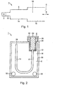
- FIG 1
- ein Aufbauschema für einen Prüfkörper, und
- FIG 2 bis 5
- jeweils einen Prüfkörper zur Überprüfung der Penetrationseigenschaften eines Sterilisiermittels.
- FIG. 1
- a construction scheme for a test specimen, and
- FIGS. 2 to 5
- in each case one test specimen for checking the penetration properties of a sterilizing agent.
Gleiche Teile sind in allen Figuren mit den selben Bezugszeichen versehen.The same parts are provided in all figures with the same reference numerals.
Der Prüfkörper 1 mit dem in Figur 1 dargestellten Aufbauschema ist zur Überprüfung der Penetrationseigenschaften eines Sterilisiermittels ausgelegt. Die beim Einsatz des Prüfkörpers 1 gewonnenen Erkenntnisse können insbesondere zur Verifizierung oder Überprüfung von Sterilisationsmaßnahmen in einem Dampfsterilisationsverfahren herangezogen werden. Bei einer derartigen Dampfsterilisation werden die zu sterilisierenden Instrumente oder Materialien in eine nicht näher dargestellte Sterilisationskammer eingebracht. Zur Sterilisation wird die Sterilisationskammer zunächst entlüftet. Der Entlüftungsprozess kann dadurch Strömungsverfahren, Über- oder Unterdruck-Entlüftungszyklen oder deren Kombination erfolgen.The test piece 1 with the construction scheme shown in Figure 1 is for verification designed the penetration properties of a sterilizing agent. The at Use of the specimen 1 gained knowledge can in particular for Verification or verification of sterilization measures in a steam sterilization process be used. In such a steam sterilization The instruments or materials to be sterilized are not closer introduced sterilization chamber introduced. For sterilization, the sterilization chamber initially deaerated. The deaeration process can thereby flow process, Over- or vacuum-venting cycles or combinations thereof.
Um bei einem derartigen, auf fraktioniertem Vakuum beruhenden Entlüftungsverfahren
nachweisen zu können, dass bei den zu sterilisierenden Instrumenten und
Materialien auch tatsächlich sämtliche inneren Oberflächen mit Sterilisiermittel
benetzt worden sind und somit die erforderliche vollständige Penetration stattgefunden
hat, wird der Prüfkörper 1 beispielsweise zur Validierung der Sterilisationsmaßnahme
bei ihrer Inbetriebnahme oder bei Routinekontrollen während des
Sterilisationsprozesses mit in der Sterilisationskammer eingesetzt. Der Prüfkörper
1 umfasst einen Detektor 2, der für den gezielten Nachweis ausgelegt ist, dass
eine Benetzung durch Sterilisiermittel tatsächlich stattgefunden hat.With such a fractionated vacuum based deaeration process
be able to prove that in the instruments to be sterilized and
Materials, in fact, all internal surfaces with sterilizer
have been wetted and thus the required complete penetration took place
has, the test specimen 1, for example, to validate the sterilization measure
during commissioning or during routine checks during the
Sterilization process used in the sterilization chamber. The test piece
1 comprises a
Der Prüfkörper 1 ist dafür ausgebildet, die ordnungsgemäße Benetzung auch vergleichsweise
schwer zugänglicher innerer Oberflächen von Instrumenten oder
Materialien geeignet nachzubilden. Dazu ist dem Detektor 2 ein Gassammelraum
4 vorgeschaltet, dessen Endmündung 6 offen gehalten ist, so dass der Detektor 2,
wie durch den Doppelpfeil 8 angedeutet, über den Gassammelraum 4 gasseitig
mit der Sterilisationskammer verbunden ist. Der Prüfkörper 1 ist dabei für eine
besonders kompakte Bauweise bei gleichzeitig besonders hoher Nachweisempfindlichkeit
hinsichtlich der Penetrationseigenschaften der zu simulierenden Instrumente
oder Gerätschaften ausgebildet. Dazu ist der Gassammelraum 4 mehrstufig
ausgeführt, wobei im Ausführungsbeispiel eine dem Detektor 2 unmittelbar
benachbarte erste Stufe 12 gasseitig mit weiteren Stufen 14, 16 in Reihe geschaltet
ist. Selbstverständlich können in Ergänzung einer derartigen dreistufigen
Ausführung auch noch weitere Stufen hintereinandergeschaltet sein, oder es kann
eine zweistufige Ausführung vorgesehen sein.The specimen 1 is designed to the proper wetting and comparatively
difficult to access internal surfaces of instruments or
To emulate materials suitably. For this purpose, the
Der Prüfkörper 1 ist in besonderem Maße für eine Anwendung bei einem dampfbasierten
Sterilisationsverfahren unter Verwendung einer Sterilisationskammer mit
besonders hoher Nachweisgenauigkeit ausgelegt. Dazu wird der Prüfkörper 1
gemeinsam mit den zu sterilisierenden Instrumenten oder Materialien in die Sterilisationskammer
eingebracht. Im ersten Bearbeitungsschritt, in dem die Sterilisationskammer
evakuiert wird, wird auch der mehrstufige ausgebildete Gassammelraum
4 evakuiert. Anschließend, wenn die Sterilisationskammer mit Dampf als
Sterilisiermittel befüllt wird, strömt der Dampf über die Endmündung 6 auch in die
dritte Stufe 16 und von dieser aus in die zweite und erste Stufe 12, 14 des Gassammelraums
4 ein. Eventuell noch vorhandene Restluft, die durch die Bildung
von Luftpolstern eine zuverlässige Sterilisation der Instrumente oder Materialien
verhindern könnte, wird dabei über die dritte Stufe 16 in die zweite und erste Stufe
12, 14 des Gassammelraums 4 hineingedrückt und sammelt sich an dessen der
Endmündung 6 gegenüber liegendem Ende. Somit erfolgt eine Aufkonzentration
der Restluft im Bereich des Detektors 2, so dass eine vollständige Benetzung eines
im Detektor angeordneten Indikators mit dem als Sterilisiermittel vorgesehen
Dampf unterbleibt.The specimen 1 is particularly suitable for use in a vapor-based
Sterilization method using a sterilization chamber with
designed especially high detection accuracy. For this purpose, the test specimen is 1
together with the instruments or materials to be sterilized in the sterilization chamber
brought in. In the first processing step, in which the sterilization chamber
is evacuated, is also the multi-level trained
In sukzessiv erfolgenden weiteren Verfahrensschritten, bei denen in der Art eines
fraktionierenden Vakuums erneut ein Unterdruck in der Sterilisationskammer erzeugt
und diese anschließend mit Dampf als Sterilisiermittel befüllt wird, erfolgt ein
sukzessiv zunehmender Austrag der Restluft aus der Sterilisationskammer. Dadurch
erfolgt eine zunehmend zuverlässige und durchgängige Benetzung sämtlicher
inneren Oberflächen der Instrumente, die analog auch zu einer zunehmend
besseren Benetzung der Innenoberfläche der ersten Stufe 12 des Gassammelraums
4 führt. Falls eine ausreichende Penetration des Sterilisiermittels in den
Prüfkörper 1 hinein erfolgt, kann eine durchgängige Benetzung auch des Indikators
festgestellt werden. Wenn dies eintritt, wird die Sterilisationsmaßnahme als
erfolgreich angesehen.In successive further process steps, in which in the manner of
fractional vacuum again generates a negative pressure in the sterilization chamber
and this is then filled with steam as a sterilant, takes place
successively increasing discharge of the residual air from the sterilization chamber. Thereby
an increasingly reliable and continuous wetting of all
internal surfaces of the instruments, which are analogous to an increasingly
better wetting of the inner surface of the
Durch die mehrstufige Ausgestaltung des Gassammelraums 4 mittels der gasseitigen
Vorschaltung der zweiten und dritten Stufe 14, 16 vor die erste Stufe 12 und
durch die geeignet gewählte Dimensionierung der Stufen 12, 14, 16 ist beim Prüfkörper
1 sichergestellt, dass die für den Prozess schädliche Restluft im unmittelbaren
Bereich der ersten Stufe 12 gezielt aufkonzentriert wird. Diese Aufkonzentration
erfolgt insbesondere durch die gasseitig vorgelagerten Stufe 14, 16, die als
Kondensationszone für das Sterilisiermittel dient und eine selektive lokale Auskondensation
des Sterilisiermittels unmittelbar vor dem Eintrittsbereich in die erste
Stufe 12 bewirkt. Durch die damit erreichte Aufkonzentration der Restluft oder anderer
nicht kondensierbarer Gase erfolgt ein nachhaltiger und besonders zuverlässiger
Nachweis der Restluft oder andere nicht kondensierbare Gase, so dass
der Prüfkörper 1 mit einer besonders hohen Nachweisgenauigkeit betrieben werden
kann.Due to the multi-stage design of the
Ein nach dem Aufbauschema gemäß Figur 1 aufgebauter Prüfkörper 1 ist in Figur
2 geschachtelt gezeigt. Dessen Detektor 2 umfasst eine mit einem Gewinde versehene
Detektorhülse 20, die mit einem aufgeschraubten Deckel 22 verschließbar
ist. Innerhalb der Detektorhülse 20 ist ein Detektorvolumen 24 von im Ausführungsbeispiel
etwa 240 µl vorgesehen, in das ein auswechselbarer Indikator 26
eingebracht ist.A constructed according to the construction scheme of Figure 1 specimen 1 is shown in FIG
2 boxed shown. Its
Der Indikator 26, der im Ausführungsbeispiel ein Volumen von etwa 120µl einnimmt
und das Detektorvolumen 24 somit annähernd zur Hälfte ausfüllt, könnte
als Sensor zur Ermittlung eines physikalischen Messwerts, beispielsweise der
Temperatur oder des Drucks, ausgelegt sein. Im Ausführungsbeispiel ist als Indikator
26 jedoch ein Bio- oder Chemo-Indikator vorgesehen. Bei der Ausgestaltung
als Bio-Indikator ist der Indikator 26 dabei an seiner Oberfläche mit keimfähigen
Kulturen versetzt, die bei einer ordnungsgemäßen Benetzung mit Dampf als Sterilisiermittel
abgetötet werden. Bei dieser Ausgestaltung wird der Indikator 26 also
derart eingesetzt, dass nach erfolgter Sterilisation eine Überprüfung auf noch
vermehrungsfähige Keime vorgenommen wird. Falls solche festgestellt werden,
wird auf unzureichende Sterilisation geschlossen.The
Bei einer Ausgestaltung des Indikators 26 als Chemo-Indikator ist dieser derart
ausgebildet, dass er bei einer Benetzung seiner Oberfläche mit Dampf als Sterilisiermittel
seine Farbe ändert, so dass durch optische Kontrolle direkt auf eine
durchgängige Benetzung geschlossen werden kann. Bei Nicht-Benetzung erfolgt
kein oder ein anderer Farbumschlag. Die erste Stufe 14 des Gassammelraums 4
ist im Wesentlichen aus einer lang gestreckten Röhre mit rundem oder auch eckigem
Querschnitt und bevorzugt aus Metall oder Kunststoff gebildet. Im Ausführungsbeispiel
nach Figur 2 weist die dem Detektor 2 unmittelbar benachbarte erste
Stufe 14 als lichte Weite einen Innendurchmesser von 2 mm auf, so dass ihr
Strömungsquerschnitt etwa 3,2 mm2 beträgt. Als Kanallänge ist etwa 50 cm gewählt.
Somit weist die erste Stufe 14 ein Innenvolumen von etwa 1,75 ml auf.In an embodiment of the
Der Detektor 2 ist dabei am einer Mündung 28 für das Gas gegenüberliegenden
Ende der ersten Stufe 14 angeordnet. Die erste Stufe 14 ist im Ausführungsbeispiel
u-förmig und somit geschwungen ausgeführt und in ihrer Gesamtheit innerhalb
eines den Innenraum der zweiten Stufe 16 umschließenden Außengehäuses
30 angeordnet, so dass sich eine geschachtelte Bauweise für den Prüfkörper 1 ergibt.
Das Außengehäuse 30 kann dabei beispielsweise im Wesentlichen als Metall-
oder Kunststoffrohr mit etwa 20 cm Länge und 25 mm Innendurchmesser
ausgestaltet sein, so dass sich ein Volumen der zweiten Stufe 16 von etwa 0,1 l
ergibt. Somit nehmen Strömungsquerschnitt und Volumen der Stufen 14, 16 zwischen
den benachbarten Stufen 14, 16 in Strömungsrichtung zum Detektor 2 hin
signifikant ab.The
Die zweite Stufe 16 kommuniziert gasseitig über eine Anzahl von im Außengehäuse
30 angeordneten Eintrittsöffnungen 32 mit der Umgebungsatmosphäre.
Gerade bei einer rohrförmigen Ausgestaltung des Außengehäuses 30 kann aber
auch dessen kompakter Bodenbereich zur Bildung einer vergleichsweise großdimensionierten
Eintrittsöffnung 32 offengehalten sein. Die Mündung 28, über die
die erste Stufe 14 gasseitig mit dem die zweite Stufe 16 des Gassammelraums 4
bildenden Innenvolumen des Außengehäuses 30 verbunden ist, ist dabei innerhalb
der Außengehäuses 30 an einer Position angeordnet, an der im Hinblick auf
die Positionierung der Eintrittsöffnungen 32 auch bei Gaswechseln mit nur geringen
Gasströmungsintensitäten zu rechnen ist, so dass die gewünschte lokale Aufkonzentration
von Gasresten durch lokale selektive Auskondensation des Sterilisiermittels
noch weiter begünstigt ist. Im Ausführungsbeispiel nach Figur 2, bei
dem die Eintrittsöffnungen 32 in den unteren Ecken des Außengehäuses 30 vorgesehen
sind, erweist sich anhand dieser Kriterien eine Positionierung der Mündung
28 im oberen Bereich des Innenvolumens als günstig.The
Alternative Ausführungsformen für den Prüfkörper 1 sind schematisch in den Figuren
3 bis 5 dargestellt. Beim Prüfkörper 1 nach Figur 3 ist die erste Stufe 14 des
Gassammelraums 4 ebenfalls in der Art einer geschachtelten Bauweise innerhalb
der zweiten Stufe 16 des Gassammelraums 4 geführt. Der Prüfkörper 1 ist in diesem
Fall jedoch für eine besonders hohe Nachweisempfindlichkeit bei besonders
kompakter Bauweise ausgeführt. Um die für eine hohe Nachweisempfindlichkeit
günstige vergleichsweise große Kanallänge der ersten Stufe 14 auch bei kompakter
Bauweise herzustellen, ist die erste Stufe 14 in dieser Ausführungsform in
der Art einer Wendel innerhalb des die zweite Stufe 16 umschließenden Außengehäuses
30 geführt. Als Eintrittsöffnung 32 ist in diesem Fall der komplette Bodenbereich
des Außengehäuses 30 offen gehalten. Im Hinblick auf die genannten
Kriterien muss die Positionierung der Mündung 28 nahe dem Deckelbereich des
Außengehäuses 30 erfolgen.Alternative embodiments of the test specimen 1 are shown schematically in the figures
3 to 5 shown. When test specimen 1 of Figure 3, the
Beim Prüfkörper 1 nach Figur 4 ist die erste Stufe 14 des Gassammelraums 4
nicht innerhalb, sondern vielmehr außerhalb der zweiten Stufe 16 angeordnet und
spiralartig um das Außengehäuse 30 der zweiten Stufe 16 herumgeführt. Bei geeignet
dicker Wandstärke des Außengehäuses 30 kann die erste Stufe 14 in dieser
Ausführungsform auch vollständig in die Außenwand integriert sein.In the test body 1 according to FIG. 4, the
In der Ausführungsform nach Figur 5 weist der Prüfkörper 1 ein im Wesentlichen
kastenförmig ausgebildetes Außengehäuse 30 zur Begrenzung des Gassammelraums
4 auf. Der im Wesentlichen u-förmig ausgestaltete erste Stufe 14 ist in diesem
Fall ebenfalls nahezu vollständig im Innenraum der zweiten Stufe 16 geführt.
Beim Prüfkörper 1 ist die zweite Stufe 16 zudem mit porösem Material 34, insbesondere
mit Zellulose-, Baum-, Glas-, Stein- oder Metallwolle, gefüllt. In the embodiment according to FIG. 5, the test body 1 has a substantially
box-shaped
- 11
- Prüfkörperspecimen
- 22
- Detektordetector
- 44
- GassammelraumGas collection space
- 66
- Endmündungend opening
- 88th
- Doppelpfeildouble arrow
- 12, 14, 1612, 14, 16
- Stufestep
- 2020
- Detektorhülsedetector sleeve
- 2121
- Deckelcover
- 2424
- Detektorvolumendetector volume
- 2626
- Indikatorindicator
- 2828
- Mündungmuzzle
- 3030
- Außengehäuseouter casing
- 3232
- Eintrittsöffnunginlet opening
- 3434
- Poröses MaterialPorous material
Claims (10)
- Test device (1), especially to test the penetration characteristics of a sterilization agent with a detector-volume (24) designed to house an indicator (26) connected to a sterilization chamber via a gas-collection-volume (4) characterized by the gas-collection-volume being multi-stage-designed so that both cross section and volume of each stage (12, 14, 16) decrease between neighbouring volumes (12, 14, 16) towards the direction of the detector volume.
- Test device (1) according to claim 1, where the cross section between neighbouring volumes (12, 14, 16) decreases towards the direction of the detector volume (24) by a minimum of 50%, better more than 75%.
- Test device (1) according to claim 1 or 2, where the cross section of the gas-collection-volume (4) directly adjacent to the detector volume (24) is ca. 1 to 200 mm2.
- Test device (1) according to one of the claims 1 to 3, where the gas-collection-volume (4) directly adjacent to the detector volume (24) has a channel length of minimum 10 cm, better ca. 30 to 100 cm.
- Test device (1) according to one of the claims 1 to 4, where one stage (14) of the gas-collection-volume (4) is arranged within another stage (16) of the gas-collection-volume (4).
- Test device (1) according to claim 5, where the next stage (16) of the gas-collection-volume (4) is formed by an outside case (30) enclosing the first stage (14).
- Test device (1) according to one of the claims 1 to 4, where one stage (14) of the gas-collection-volume (4) is built around an outside case (30) which forms another stage (16) of the gas-collection-volume (4).
- Test device (1) according to one of the claims 1 to 7, where at least one stage (14, 16) of the gas-collection-volume (4) is filled with porous material (34).
- Test device (1) according to one of the claims 1 to 8, where the detector volume (24) is selected to be smaller than 500 µl.
- Test device (1) according to one of the claims 1 to 9, where a chemical or biological indicator is used as an indicator (26).
Priority Applications (18)
| Application Number | Priority Date | Filing Date | Title |
|---|---|---|---|
| DK03007122T DK1468701T3 (en) | 2003-03-28 | 2003-03-28 | Test body, in particular for testing the penetration properties of a sterilizer in sterilization processes |
| EP03007122A EP1468701B1 (en) | 2003-03-28 | 2003-03-28 | Challenge device, especially for testing the penetration properties of a sterilant in sterilising processes |
| AT03007122T ATE297227T1 (en) | 2003-03-28 | 2003-03-28 | TEST SPECIMEN, IN PARTICULAR FOR CHECKING THE PENETRATION PROPERTIES OF A STERILIZING AGENT IN STERILIZATION PROCESSES |
| PT03007122T PT1468701E (en) | 2003-03-28 | 2003-03-28 | CONTROL UNIT FOR THE VERIFICATION OF THE PENETRATING PROPERTIES OF A STERILIZER USED IN STERILIZATION PROCESSES |
| DE50300631T DE50300631D1 (en) | 2003-03-28 | 2003-03-28 | Test specimens, in particular for checking the penetration properties of a sterilizing agent in sterilization processes |
| ES03007122T ES2246027T3 (en) | 2003-03-28 | 2003-03-28 | SPECIAL TEST DEVICE TO CONTROL THE PENETRATION CHARACTERISTICS OF A STERILIZING AGENT IN THE STERILIZATION PROCESSES. |
| PCT/EP2004/003198 WO2004084956A1 (en) | 2003-03-28 | 2004-03-26 | Testing body, particularly for verifying the penetration properties of a sterilizing agent in sterilization processes |
| JP2006504869A JP4359612B2 (en) | 2003-03-28 | 2004-03-26 | Process test equipment to verify the penetration characteristics of sterilant in sterilization process |
| KR1020057018396A KR100726344B1 (en) | 2003-03-28 | 2004-03-26 | Testing body, particularly for verifying the penetration properties of a sterilizing agent in sterilization processes |
| US10/551,146 US7862769B2 (en) | 2003-03-28 | 2004-03-26 | Testing body, particularly for verifying the penetration properties of a sterilizing agent in sterilization processes |
| NZ542783A NZ542783A (en) | 2003-03-28 | 2004-03-26 | Test device, especially for testing the penetration characteristics of a sterilization agent in sterilization processes |
| MXPA05010418A MXPA05010418A (en) | 2003-03-28 | 2004-03-26 | Testing body, particularly for verifying the penetration properties of a sterilizing agent in sterilization processes. |
| BRPI0408908-1A BRPI0408908A (en) | 2003-03-28 | 2004-03-26 | control body, in particular for checking the penetration properties of a sterilant used in sterilization processes |
| RU2005130397/15A RU2316356C2 (en) | 2003-03-28 | 2004-03-26 | Test body for inspection of penetrating properties of sterilizing aid during sterilization process |
| AU2004224765A AU2004224765B2 (en) | 2003-03-28 | 2004-03-26 | Testing body, particularly for verifying the penetration properties of a sterilizing agent in sterilization processes |
| CA002520692A CA2520692C (en) | 2003-03-28 | 2004-03-26 | Testing body, particularly for verifying the penetration properties of a sterilizing agent in sterilization processes |
| CNB2004800113930A CN100354012C (en) | 2003-03-28 | 2004-03-26 | Testing body, particularly for verifying the penetration properties of a sterilizing agent in sterilization processes |
| ZA200508402A ZA200508402B (en) | 2003-03-28 | 2005-10-17 | Testing body, particularly for verifying the penetration properties of a sterilizing agent in sterilization processes |
Applications Claiming Priority (1)
| Application Number | Priority Date | Filing Date | Title |
|---|---|---|---|
| EP03007122A EP1468701B1 (en) | 2003-03-28 | 2003-03-28 | Challenge device, especially for testing the penetration properties of a sterilant in sterilising processes |
Publications (2)
| Publication Number | Publication Date |
|---|---|
| EP1468701A1 EP1468701A1 (en) | 2004-10-20 |
| EP1468701B1 true EP1468701B1 (en) | 2005-06-08 |
Family
ID=32892861
Family Applications (1)
| Application Number | Title | Priority Date | Filing Date |
|---|---|---|---|
| EP03007122A Expired - Lifetime EP1468701B1 (en) | 2003-03-28 | 2003-03-28 | Challenge device, especially for testing the penetration properties of a sterilant in sterilising processes |
Country Status (18)
| Country | Link |
|---|---|
| US (1) | US7862769B2 (en) |
| EP (1) | EP1468701B1 (en) |
| JP (1) | JP4359612B2 (en) |
| KR (1) | KR100726344B1 (en) |
| CN (1) | CN100354012C (en) |
| AT (1) | ATE297227T1 (en) |
| AU (1) | AU2004224765B2 (en) |
| BR (1) | BRPI0408908A (en) |
| CA (1) | CA2520692C (en) |
| DE (1) | DE50300631D1 (en) |
| DK (1) | DK1468701T3 (en) |
| ES (1) | ES2246027T3 (en) |
| MX (1) | MXPA05010418A (en) |
| NZ (1) | NZ542783A (en) |
| PT (1) | PT1468701E (en) |
| RU (1) | RU2316356C2 (en) |
| WO (1) | WO2004084956A1 (en) |
| ZA (1) | ZA200508402B (en) |
Cited By (4)
| Publication number | Priority date | Publication date | Assignee | Title |
|---|---|---|---|---|
| US9114186B2 (en) | 2008-05-05 | 2015-08-25 | 3M Innovative Properties Company | Sterilization process challenge device |
| US9334521B2 (en) | 2008-11-06 | 2016-05-10 | 3M Innovative Properties Company | Process challenge device and methods |
| WO2020038566A2 (en) | 2018-08-21 | 2020-02-27 | Gke Gmbh | Multi-stage process challenge device, indicator system and process challenge device system |
| DE202023002155U1 (en) | 2023-10-17 | 2023-12-08 | PFERBECK UG (haftungsbeschränkt) | Chemo-indicator system for the significant detection of inert gases during steam sterilization with upstream venting stages |
Families Citing this family (15)
| Publication number | Priority date | Publication date | Assignee | Title |
|---|---|---|---|---|
| WO2005053755A1 (en) | 2003-12-05 | 2005-06-16 | Olympus Corporation | Sterilization confirming test element and test pack |
| CN101444632B (en) * | 2009-01-15 | 2012-08-08 | 杭州三源医疗设备有限公司 | Peroxide plasma body sterilizing equipment effect verification device and method and indicator used |
| DE102010016017B4 (en) * | 2010-03-18 | 2014-02-20 | MMM Münchner Medizin Mechanik GmbH | sterilizer |
| US8486691B2 (en) | 2010-04-12 | 2013-07-16 | Sterilucent, Inc. | Apparatus for assessing the effectiveness of a sterilization process |
| AU2014244561B2 (en) * | 2013-03-13 | 2018-01-25 | Stryker Corporation | Sterilization container capable of providing an indication regarding whether or not surgical instruments sterilized in the container were properly sterilized |
| CN104034635B (en) * | 2014-05-30 | 2016-06-08 | 河海大学 | What colloid penetrated in dust devil measures intelligence experimental provision and operational approach thereof in real time |
| CN105999337B (en) * | 2016-07-18 | 2018-08-21 | 四川科伦药业股份有限公司 | A kind of biological indicator storing unit for pipeline steam sterilizing |
| CN106267277B (en) * | 2016-09-28 | 2022-09-09 | 中国科学院苏州生物医学工程技术研究所 | Biological indicator detection device for monitoring sterilization effect of lumen instruments |
| RU176693U1 (en) * | 2017-09-15 | 2018-01-25 | Общество с ограниченной ответственностью "Научно-производственная фирма "ВИНАР" | DEVICE FOR MONITORING THE EFFICIENCY OF CLEANING A MEDICAL INSTRUMENT IN A WASHING MACHINE |
| US10814027B2 (en) * | 2017-12-07 | 2020-10-27 | Asp Global Manufacturing Gmbh | Sterilization-assistance device |
| US10967084B2 (en) | 2017-12-15 | 2021-04-06 | Asp Global Manufacturing Gmbh | Flow restrictor |
| JP2022511694A (en) * | 2018-11-12 | 2022-02-01 | ゲーカーエー ゲーエムベーハー | Tapered indicator used in process challenge devices |
| CN113784736A (en) * | 2019-05-02 | 2021-12-10 | 3M创新有限公司 | Sterilization test bag |
| RU2736183C1 (en) * | 2019-12-26 | 2020-11-12 | Федеральное бюджетное учреждение науки «Научно-исследовательский институт дезинфектологии» Федеральной службы по надзору в сфере защиты прав потребителей и благополучия человека | Method for evaluating efficiency of endoscope aseptic storage device |
| WO2022012757A1 (en) * | 2020-07-17 | 2022-01-20 | Gke Gmbh | Process challenge device (pcd) with variable sensitivity adaption |
Family Cites Families (8)
| Publication number | Priority date | Publication date | Assignee | Title |
|---|---|---|---|---|
| DE8700471U1 (en) * | 1987-01-10 | 1987-03-05 | Versloot C S P | |
| EP0628814A1 (en) * | 1993-06-14 | 1994-12-14 | Ulrich Dr. Kaiser | Indicator test system for monitoring air removal and/or sterilisation of full loads in steam sterilisers |
| DE69620209T2 (en) | 1995-10-06 | 2002-11-07 | Minnesota Mining & Mfg | TEST SYSTEMS FOR STERILIZERS |
| US5872004A (en) * | 1997-04-08 | 1999-02-16 | Steris Corporation | Test pack for assessing the efficiency of a sterilization process |
| DE19724155A1 (en) * | 1997-06-07 | 1998-12-10 | Secundus Medizinische Kontroll | Sterilization test device |
| DE29811381U1 (en) * | 1998-06-25 | 1998-10-01 | Secundus Medizinische Kontroll | Sterilization test device |
| DE19838678C2 (en) * | 1998-08-20 | 2001-08-23 | Melagapp Gmbh & Co Kg | Steam sterilizer |
| DE19944847C1 (en) * | 1999-09-18 | 2001-05-03 | Secundus Medizinische Kontroll | Sterilization test device |
-
2003
- 2003-03-28 DE DE50300631T patent/DE50300631D1/en not_active Expired - Lifetime
- 2003-03-28 ES ES03007122T patent/ES2246027T3/en not_active Expired - Lifetime
- 2003-03-28 PT PT03007122T patent/PT1468701E/en unknown
- 2003-03-28 EP EP03007122A patent/EP1468701B1/en not_active Expired - Lifetime
- 2003-03-28 AT AT03007122T patent/ATE297227T1/en not_active IP Right Cessation
- 2003-03-28 DK DK03007122T patent/DK1468701T3/en active
-
2004
- 2004-03-26 MX MXPA05010418A patent/MXPA05010418A/en active IP Right Grant
- 2004-03-26 BR BRPI0408908-1A patent/BRPI0408908A/en not_active IP Right Cessation
- 2004-03-26 NZ NZ542783A patent/NZ542783A/en not_active IP Right Cessation
- 2004-03-26 US US10/551,146 patent/US7862769B2/en active Active
- 2004-03-26 RU RU2005130397/15A patent/RU2316356C2/en not_active IP Right Cessation
- 2004-03-26 CA CA002520692A patent/CA2520692C/en not_active Expired - Fee Related
- 2004-03-26 CN CNB2004800113930A patent/CN100354012C/en not_active Expired - Lifetime
- 2004-03-26 JP JP2006504869A patent/JP4359612B2/en not_active Expired - Fee Related
- 2004-03-26 AU AU2004224765A patent/AU2004224765B2/en not_active Ceased
- 2004-03-26 WO PCT/EP2004/003198 patent/WO2004084956A1/en active IP Right Grant
- 2004-03-26 KR KR1020057018396A patent/KR100726344B1/en not_active IP Right Cessation
-
2005
- 2005-10-17 ZA ZA200508402A patent/ZA200508402B/en unknown
Cited By (4)
| Publication number | Priority date | Publication date | Assignee | Title |
|---|---|---|---|---|
| US9114186B2 (en) | 2008-05-05 | 2015-08-25 | 3M Innovative Properties Company | Sterilization process challenge device |
| US9334521B2 (en) | 2008-11-06 | 2016-05-10 | 3M Innovative Properties Company | Process challenge device and methods |
| WO2020038566A2 (en) | 2018-08-21 | 2020-02-27 | Gke Gmbh | Multi-stage process challenge device, indicator system and process challenge device system |
| DE202023002155U1 (en) | 2023-10-17 | 2023-12-08 | PFERBECK UG (haftungsbeschränkt) | Chemo-indicator system for the significant detection of inert gases during steam sterilization with upstream venting stages |
Also Published As
| Publication number | Publication date |
|---|---|
| KR20060009242A (en) | 2006-01-31 |
| CN1780645A (en) | 2006-05-31 |
| AU2004224765B2 (en) | 2008-06-26 |
| JP2006521134A (en) | 2006-09-21 |
| BRPI0408908A (en) | 2006-03-28 |
| RU2316356C2 (en) | 2008-02-10 |
| US7862769B2 (en) | 2011-01-04 |
| JP4359612B2 (en) | 2009-11-04 |
| ATE297227T1 (en) | 2005-06-15 |
| RU2005130397A (en) | 2006-06-10 |
| DE50300631D1 (en) | 2005-07-14 |
| ES2246027T3 (en) | 2006-02-01 |
| US20070178549A1 (en) | 2007-08-02 |
| CA2520692C (en) | 2008-06-10 |
| ZA200508402B (en) | 2008-08-27 |
| PT1468701E (en) | 2005-10-31 |
| CA2520692A1 (en) | 2004-10-07 |
| NZ542783A (en) | 2007-05-31 |
| KR100726344B1 (en) | 2007-06-11 |
| EP1468701A1 (en) | 2004-10-20 |
| AU2004224765A1 (en) | 2004-10-07 |
| DK1468701T3 (en) | 2005-10-10 |
| CN100354012C (en) | 2007-12-12 |
| WO2004084956A1 (en) | 2004-10-07 |
| MXPA05010418A (en) | 2006-05-31 |
Similar Documents
| Publication | Publication Date | Title |
|---|---|---|
| EP1468701B1 (en) | Challenge device, especially for testing the penetration properties of a sterilant in sterilising processes | |
| DE10296927B4 (en) | Apparatus for assessing a cleaning process of endoscopes | |
| EP2216648B1 (en) | Cleaning indicator and test body for testing cleaning processes | |
| DE69721499T2 (en) | SYSTEM AND METHOD FOR REAL-TIME MONITORING AND CONTROL OF TREATMENT STERLIZATION AND PARAMETRIC RELEASE | |
| EP2557417B1 (en) | Replacement fitting | |
| DE102008010948A1 (en) | Method for calibrating a sensor within a chamber; Sensor, disposable and treatment device with such a sensor | |
| DE102005051279A1 (en) | Fitting for receiving a probe | |
| EP3280459A1 (en) | Process challenge device for automated endoscope reprocessor | |
| DE202006006926U1 (en) | Device for testing effectiveness of autoclave steam sterilization, e.g. of medical articles, via temperature measurements, including sensors in sterilization zone and removable, easily cleaned measuring chamber | |
| EP0628814A1 (en) | Indicator test system for monitoring air removal and/or sterilisation of full loads in steam sterilisers | |
| DE112018007917T5 (en) | Multi-stage process test body, indicator system and process test body system | |
| US7608219B2 (en) | Sterilizer test device | |
| EP1550467B1 (en) | Test device for checking the permeation properties of a sterilising agent in sterilisation processes | |
| EP3671184B1 (en) | Alcohol detection device with redundant measurement channels and method for detecting alcohol | |
| DE19852793A1 (en) | Sterilizer with a sensor and method for monitoring the sensor | |
| EP0808631A1 (en) | Measuring device for controlling sterilization conditions | |
| EP3299036B1 (en) | Validation set and method for testing the cleaning performance of a cleaning device | |
| DE102015003745B4 (en) | Mobile testing device, gas meter and system for testing a gas meter | |
| DE102008063273A1 (en) | Test device for endoscope washing machine | |
| DE112018008133T5 (en) | Conical indicator for use in process test pieces | |
| DE202016005870U1 (en) | Air and leak detector for steam sterilizers | |
| WO2020249243A1 (en) | Method for determining the effectiveness of a sterilization method for a medical product in a sterilizer, data processing system, computer program product, and medical product | |
| DE60110590T2 (en) | CONTROL STICK | |
| DE202013004024U1 (en) | Device for determining a content of noncondensable gases (NKG) in a sterilization steam | |
| EP3457115A1 (en) | Device for detecting and method for determining a steam concentration in a sterilizer and sterilizer |
Legal Events
| Date | Code | Title | Description |
|---|---|---|---|
| PUAI | Public reference made under article 153(3) epc to a published international application that has entered the european phase |
Free format text: ORIGINAL CODE: 0009012 |
|
| GRAP | Despatch of communication of intention to grant a patent |
Free format text: ORIGINAL CODE: EPIDOSNIGR1 |
|
| 17P | Request for examination filed |
Effective date: 20031216 |
|
| AK | Designated contracting states |
Kind code of ref document: A1 Designated state(s): AT BE BG CH CY CZ DE DK EE ES FI FR GB GR HU IE IT LI LU MC NL PT RO SE SI SK TR |
|
| AX | Request for extension of the european patent |
Extension state: AL LT LV MK |
|
| GRAS | Grant fee paid |
Free format text: ORIGINAL CODE: EPIDOSNIGR3 |
|
| GRAA | (expected) grant |
Free format text: ORIGINAL CODE: 0009210 |
|
| AK | Designated contracting states |
Kind code of ref document: B1 Designated state(s): AT BE BG CH CY CZ DE DK EE ES FI FR GB GR HU IE IT LI LU MC NL PT RO SE SI SK TR |
|
| PG25 | Lapsed in a contracting state [announced via postgrant information from national office to epo] |
Ref country code: RO Free format text: LAPSE BECAUSE OF FAILURE TO SUBMIT A TRANSLATION OF THE DESCRIPTION OR TO PAY THE FEE WITHIN THE PRESCRIBED TIME-LIMIT Effective date: 20050608 Ref country code: EE Free format text: LAPSE BECAUSE OF FAILURE TO SUBMIT A TRANSLATION OF THE DESCRIPTION OR TO PAY THE FEE WITHIN THE PRESCRIBED TIME-LIMIT Effective date: 20050608 Ref country code: FI Free format text: LAPSE BECAUSE OF FAILURE TO SUBMIT A TRANSLATION OF THE DESCRIPTION OR TO PAY THE FEE WITHIN THE PRESCRIBED TIME-LIMIT Effective date: 20050608 Ref country code: SI Free format text: LAPSE BECAUSE OF FAILURE TO SUBMIT A TRANSLATION OF THE DESCRIPTION OR TO PAY THE FEE WITHIN THE PRESCRIBED TIME-LIMIT Effective date: 20050608 Ref country code: SK Free format text: LAPSE BECAUSE OF FAILURE TO SUBMIT A TRANSLATION OF THE DESCRIPTION OR TO PAY THE FEE WITHIN THE PRESCRIBED TIME-LIMIT Effective date: 20050608 |
|
| REG | Reference to a national code |
Ref country code: GB Ref legal event code: FG4D Free format text: NOT ENGLISH |
|
| REG | Reference to a national code |
Ref country code: CH Ref legal event code: EP |
|
| AKX | Designation fees paid |
Designated state(s): AT BE BG CH CY CZ DE DK EE ES FI FR GB GR HU IE IT LI LU MC NL PT RO SE SI SK TR |
|
| REF | Corresponds to: |
Ref document number: 50300631 Country of ref document: DE Date of ref document: 20050714 Kind code of ref document: P |
|
| REG | Reference to a national code |
Ref country code: IE Ref legal event code: FG4D Free format text: LANGUAGE OF EP DOCUMENT: GERMAN |
|
| PG25 | Lapsed in a contracting state [announced via postgrant information from national office to epo] |
Ref country code: BG Free format text: LAPSE BECAUSE OF FAILURE TO SUBMIT A TRANSLATION OF THE DESCRIPTION OR TO PAY THE FEE WITHIN THE PRESCRIBED TIME-LIMIT Effective date: 20050908 Ref country code: GR Free format text: LAPSE BECAUSE OF FAILURE TO SUBMIT A TRANSLATION OF THE DESCRIPTION OR TO PAY THE FEE WITHIN THE PRESCRIBED TIME-LIMIT Effective date: 20050908 |
|
| PG25 | Lapsed in a contracting state [announced via postgrant information from national office to epo] |
Ref country code: ES Free format text: LAPSE BECAUSE OF FAILURE TO SUBMIT A TRANSLATION OF THE DESCRIPTION OR TO PAY THE FEE WITHIN THE PRESCRIBED TIME-LIMIT Effective date: 20050919 |
|
| REG | Reference to a national code |
Ref country code: SE Ref legal event code: TRGR |
|
| REG | Reference to a national code |
Ref country code: DK Ref legal event code: T3 |
|
| GBT | Gb: translation of ep patent filed (gb section 77(6)(a)/1977) |
Effective date: 20050917 |
|
| REG | Reference to a national code |
Ref country code: PT Ref legal event code: SC4A Effective date: 20050906 |
|
| REG | Reference to a national code |
Ref country code: CH Ref legal event code: NV Representative=s name: E. BLUM & CO. PATENTANWAELTE |
|
| PG25 | Lapsed in a contracting state [announced via postgrant information from national office to epo] |
Ref country code: HU Free format text: LAPSE BECAUSE OF FAILURE TO SUBMIT A TRANSLATION OF THE DESCRIPTION OR TO PAY THE FEE WITHIN THE PRESCRIBED TIME-LIMIT Effective date: 20051209 |
|
| REG | Reference to a national code |
Ref country code: ES Ref legal event code: FG2A Ref document number: 2246027 Country of ref document: ES Kind code of ref document: T3 |
|
| PG25 | Lapsed in a contracting state [announced via postgrant information from national office to epo] |
Ref country code: MC Free format text: LAPSE BECAUSE OF NON-PAYMENT OF DUE FEES Effective date: 20060331 Ref country code: BE Free format text: LAPSE BECAUSE OF NON-PAYMENT OF DUE FEES Effective date: 20060331 Ref country code: LU Free format text: LAPSE BECAUSE OF NON-PAYMENT OF DUE FEES Effective date: 20060331 |
|
| ET | Fr: translation filed | ||
| PLBE | No opposition filed within time limit |
Free format text: ORIGINAL CODE: 0009261 |
|
| STAA | Information on the status of an ep patent application or granted ep patent |
Free format text: STATUS: NO OPPOSITION FILED WITHIN TIME LIMIT |
|
| 26N | No opposition filed |
Effective date: 20060309 |
|
| REG | Reference to a national code |
Ref country code: CH Ref legal event code: PFA Owner name: KAISER, ULRICH, DR. Free format text: KAISER, ULRICH, DR.#FELDSTRASSE 14#D-61479 GLASHUETTEN (DE) -TRANSFER TO- KAISER, ULRICH, DR.#FELDSTRASSE 14#D-61479 GLASHUETTEN (DE) |
|
| BERE | Be: lapsed |
Owner name: KAISER, ULRICH, DR. Effective date: 20060331 |
|
| PGFP | Annual fee paid to national office [announced via postgrant information from national office to epo] |
Ref country code: CH Payment date: 20080320 Year of fee payment: 6 Ref country code: DK Payment date: 20080318 Year of fee payment: 6 |
|
| PGFP | Annual fee paid to national office [announced via postgrant information from national office to epo] |
Ref country code: CZ Payment date: 20080326 Year of fee payment: 6 Ref country code: IE Payment date: 20080320 Year of fee payment: 6 Ref country code: PT Payment date: 20080318 Year of fee payment: 6 Ref country code: SE Payment date: 20080320 Year of fee payment: 6 |
|
| PGFP | Annual fee paid to national office [announced via postgrant information from national office to epo] |
Ref country code: AT Payment date: 20080319 Year of fee payment: 6 |
|
| PGFP | Annual fee paid to national office [announced via postgrant information from national office to epo] |
Ref country code: NL Payment date: 20080318 Year of fee payment: 6 |
|
| PG25 | Lapsed in a contracting state [announced via postgrant information from national office to epo] |
Ref country code: CY Free format text: LAPSE BECAUSE OF FAILURE TO SUBMIT A TRANSLATION OF THE DESCRIPTION OR TO PAY THE FEE WITHIN THE PRESCRIBED TIME-LIMIT Effective date: 20050608 |
|
| REG | Reference to a national code |
Ref country code: PT Ref legal event code: MM4A Free format text: LAPSE DUE TO NON-PAYMENT OF FEES Effective date: 20090928 |
|
| PG25 | Lapsed in a contracting state [announced via postgrant information from national office to epo] |
Ref country code: PT Free format text: LAPSE BECAUSE OF NON-PAYMENT OF DUE FEES Effective date: 20090928 Ref country code: AT Free format text: LAPSE BECAUSE OF NON-PAYMENT OF DUE FEES Effective date: 20090328 Ref country code: CZ Free format text: LAPSE BECAUSE OF NON-PAYMENT OF DUE FEES Effective date: 20090328 |
|
| REG | Reference to a national code |
Ref country code: CH Ref legal event code: PL |
|
| REG | Reference to a national code |
Ref country code: DK Ref legal event code: EBP |
|
| EUG | Se: european patent has lapsed | ||
| NLV4 | Nl: lapsed or anulled due to non-payment of the annual fee |
Effective date: 20091001 |
|
| REG | Reference to a national code |
Ref country code: IE Ref legal event code: MM4A |
|
| PG25 | Lapsed in a contracting state [announced via postgrant information from national office to epo] |
Ref country code: CH Free format text: LAPSE BECAUSE OF NON-PAYMENT OF DUE FEES Effective date: 20090331 Ref country code: LI Free format text: LAPSE BECAUSE OF NON-PAYMENT OF DUE FEES Effective date: 20090331 Ref country code: IE Free format text: LAPSE BECAUSE OF NON-PAYMENT OF DUE FEES Effective date: 20090330 |
|
| PG25 | Lapsed in a contracting state [announced via postgrant information from national office to epo] |
Ref country code: NL Free format text: LAPSE BECAUSE OF NON-PAYMENT OF DUE FEES Effective date: 20091001 |
|
| PG25 | Lapsed in a contracting state [announced via postgrant information from national office to epo] |
Ref country code: DK Free format text: LAPSE BECAUSE OF NON-PAYMENT OF DUE FEES Effective date: 20090331 |
|
| PG25 | Lapsed in a contracting state [announced via postgrant information from national office to epo] |
Ref country code: SE Free format text: LAPSE BECAUSE OF NON-PAYMENT OF DUE FEES Effective date: 20090329 |
|
| REG | Reference to a national code |
Ref country code: FR Ref legal event code: PLFP Year of fee payment: 13 |
|
| PGFP | Annual fee paid to national office [announced via postgrant information from national office to epo] |
Ref country code: ES Payment date: 20150325 Year of fee payment: 13 |
|
| PGFP | Annual fee paid to national office [announced via postgrant information from national office to epo] |
Ref country code: GB Payment date: 20150324 Year of fee payment: 13 Ref country code: TR Payment date: 20150318 Year of fee payment: 13 Ref country code: FR Payment date: 20150319 Year of fee payment: 13 |
|
| PGFP | Annual fee paid to national office [announced via postgrant information from national office to epo] |
Ref country code: IT Payment date: 20160318 Year of fee payment: 14 |
|
| GBPC | Gb: european patent ceased through non-payment of renewal fee |
Effective date: 20160328 |
|
| REG | Reference to a national code |
Ref country code: FR Ref legal event code: ST Effective date: 20161130 |
|
| PG25 | Lapsed in a contracting state [announced via postgrant information from national office to epo] |
Ref country code: GB Free format text: LAPSE BECAUSE OF NON-PAYMENT OF DUE FEES Effective date: 20160328 Ref country code: FR Free format text: LAPSE BECAUSE OF NON-PAYMENT OF DUE FEES Effective date: 20160331 |
|
| REG | Reference to a national code |
Ref country code: ES Ref legal event code: FD2A Effective date: 20170428 |
|
| PG25 | Lapsed in a contracting state [announced via postgrant information from national office to epo] |
Ref country code: ES Free format text: LAPSE BECAUSE OF NON-PAYMENT OF DUE FEES Effective date: 20160329 |
|
| PG25 | Lapsed in a contracting state [announced via postgrant information from national office to epo] |
Ref country code: IT Free format text: LAPSE BECAUSE OF NON-PAYMENT OF DUE FEES Effective date: 20170328 |
|
| PGFP | Annual fee paid to national office [announced via postgrant information from national office to epo] |
Ref country code: DE Payment date: 20210329 Year of fee payment: 19 |
|
| PG25 | Lapsed in a contracting state [announced via postgrant information from national office to epo] |
Ref country code: TR Free format text: LAPSE BECAUSE OF NON-PAYMENT OF DUE FEES Effective date: 20160328 |
|
| REG | Reference to a national code |
Ref country code: DE Ref legal event code: R119 Ref document number: 50300631 Country of ref document: DE |
|
| PG25 | Lapsed in a contracting state [announced via postgrant information from national office to epo] |
Ref country code: DE Free format text: LAPSE BECAUSE OF NON-PAYMENT OF DUE FEES Effective date: 20221001 |