EP1549115A2 - Procédé de calculation d'exposition et dispositif de radiographie - Google Patents
Procédé de calculation d'exposition et dispositif de radiographie Download PDFInfo
- Publication number
- EP1549115A2 EP1549115A2 EP04257996A EP04257996A EP1549115A2 EP 1549115 A2 EP1549115 A2 EP 1549115A2 EP 04257996 A EP04257996 A EP 04257996A EP 04257996 A EP04257996 A EP 04257996A EP 1549115 A2 EP1549115 A2 EP 1549115A2
- Authority
- EP
- European Patent Office
- Prior art keywords
- values
- lookup table
- ray
- area
- collimator
- Prior art date
- Legal status (The legal status is an assumption and is not a legal conclusion. Google has not performed a legal analysis and makes no representation as to the accuracy of the status listed.)
- Granted
Links
Images


Classifications
-
- A—HUMAN NECESSITIES
- A61—MEDICAL OR VETERINARY SCIENCE; HYGIENE
- A61B—DIAGNOSIS; SURGERY; IDENTIFICATION
- A61B6/00—Apparatus for radiation diagnosis, e.g. combined with radiation therapy equipment
-
- A—HUMAN NECESSITIES
- A61—MEDICAL OR VETERINARY SCIENCE; HYGIENE
- A61B—DIAGNOSIS; SURGERY; IDENTIFICATION
- A61B6/00—Apparatus for radiation diagnosis, e.g. combined with radiation therapy equipment
- A61B6/54—Control of apparatus or devices for radiation diagnosis
- A61B6/542—Control of apparatus or devices for radiation diagnosis involving control of exposure
-
- G—PHYSICS
- G21—NUCLEAR PHYSICS; NUCLEAR ENGINEERING
- G21K—TECHNIQUES FOR HANDLING PARTICLES OR IONISING RADIATION NOT OTHERWISE PROVIDED FOR; IRRADIATION DEVICES; GAMMA RAY OR X-RAY MICROSCOPES
- G21K1/00—Arrangements for handling particles or ionising radiation, e.g. focusing or moderating
- G21K1/02—Arrangements for handling particles or ionising radiation, e.g. focusing or moderating using diaphragms, collimators
- G21K1/04—Arrangements for handling particles or ionising radiation, e.g. focusing or moderating using diaphragms, collimators using variable diaphragms, shutters, choppers
-
- H—ELECTRICITY
- H05—ELECTRIC TECHNIQUES NOT OTHERWISE PROVIDED FOR
- H05G—X-RAY TECHNIQUE
- H05G1/00—X-ray apparatus involving X-ray tubes; Circuits therefor
- H05G1/08—Electrical details
- H05G1/26—Measuring, controlling or protecting
- H05G1/30—Controlling
- H05G1/38—Exposure time
Definitions
- the present invention relates to an exposure calculation method and a radiography system, and more particularly, to a method of calculating an exposure a patient receives during radiography, and a radiography system including means for calculating the exposure a patient receives during radiography.
- a radiography system controls an X-ray exposure so that the X-ray exposure will be set to a predetermined value.
- the predetermined value is, for example, a minimum necessary exposure.
- a dedicated detector is used to detect or monitor an X-ray exposure during radiography.
- X-irradiation is stopped (refer to, for example, U.S. Patent No. 5,694,449 (third to fifth columns and Fig. 1 to Fig. 4)).
- the dedicated detector is needed for detecting an X-ray exposure during radiography.
- a signal processing circuit or the like is needed for performing predetermined processing that includes the temporal integral of the components of the detection signal. Therefore, the method is unsuitable for, for example, a mobile radiography system and other radiography systems requested to have a simple configuration, be lightweight, and cost low.
- an object of the present invention is to provide a method of calculating an exposure, which a patient receives during radiography, without detecting X-rays, and a radiography system including such exposure calculating means.
- the first lookup table is created through calibration of the X-ray tube performed using a dosimeter so that the relationship of correspondence between the values of the tube voltage of the X-ray tube and the values of the dose rate can be grasped properly.
- the second lookup table is created through calibration of the collimator including actual measurement of the area of the X-ray field so that the relationship of correspondence between the values each indicating the positions of the blades included in the collimator and values of the area of the X-ray field can be grasped properly.
- the relationship of correspondence between the values indicating the positions of blades, which constitute each of an iris diaphragm and a shutter included in the collimator, and the values of the area of the X-ray field is recorded in the second lookup table so that the X-ray field can be adjusted by utilizing the combination of the iris diaphragm and shutter.
- the value of the dose rate associated with the value of the tube voltage of the X-ray tube is retrieved from the first lookup table that is created in advance.
- the value of the area of the X-ray field associated with the value indicating the positions of the blades included in the collimator that limits the range of X-ray radiation is retrieved from the second lookup table that is created in advance.
- the product of the dose rate, the area of the X-ray field, the tube current of the X-ray tube, and an X-irradiation time is calculated.
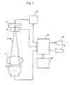
- Fig. 1 is a block diagram showing a radiography system.
- the radiography system is an example of the best mode for implementing the present invention.
- the configuration of the radiography system provides an example of a radiography system in which the present invention is implemented in the best mode.
- Actions to be performed in the radiography system provide an example of an exposure calculation method in which the present invention is implemented in the best mode.
- the radiography system includes an X-ray tube 10. X-rays generated from the focal spot F in the X-ray tube 10 are irradiated to a patient P via a collimator 20. The transmitted X-rays fall on the incidence surface of an image intensifier 30.
- the image intensifier 30 shall be called the I.I. 30.
- the X-ray tube 10 is driven by an X-ray tube driver 40.
- the X-ray tube driver 40 causes a tube voltage and a tube current to develop at or flows through the X-ray tube 10 so that the X-ray tube will generate X-rays.
- the X-ray tube driver 40 is controlled by a data processor 50.
- the data processor 50 is realized with, for example, a computer.
- the data processor 50 controls the collimator 20 so as to adjust an X-ray field.
- the collimator 20 includes blades whose positions are variable. By changing the positions of the blades, the X-ray field can be varied.
- a detector incorporated in the collimator 20 detects the positions of the blades and feeds the detected positions back to the data processor 50. The collimator 20 will be described later.
- the data processor 50 receives an X-ray detection signal from the I.I. 30, and constructs an image based on the input signal.
- the image is a fluoroscopic image of the patient P visualized with X-rays.
- the fluoroscopic image is displayed on a display unit 60 included in the data processor 50 and utilized for diagnosis.
- the data processor 50 includes an operating unit 70.
- the operating unit 70 and display unit 60 provide a user interface, whereby a user can operate the radiography system interactively.
- the data processor 50 includes an exposure calculation unit 80.
- the exposure calculation unit 80 is realized with, for example, a computer.
- the exposure calculation unit 80 may be incorporated in the data processor 50.
- the exposure calculation unit 80 calculates an exposure, which the patient P receives, on the basis of data received from the data processor 50, and transmits the result of the calculation to the data processor 50.
- the data processor 50 controls radiography according to the calculated exposure value.
- the foregoing components started with the X-ray tube 10 and ended with the operating unit 70 constitute an example of an imaging means included in the present invention.
- the exposure calculation unit 80 serves as an example of a detecting means included in the present invention.
- Fig. 2 is a block diagram showing the exposure calculation unit 80.
- the exposure calculation unit 80 comprises a calculation block 802 and lookup tables 804 and 806.
- the calculation block 802 references the lookup tables 804 and 806 according to data received from the data processor 50, and calculates an exposure. The calculation of an exposure will be described later.
- the calculation block 802 serves as an example of a calculating means included in the present invention.
- the lookup table 804 serves as an example of a first lookup table included in the present invention.
- the lookup table 806 serves as a second lookup table included therein.
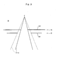
- Fig. 3 and Fig. 4 illustratively show the structure of the collimator 20.
- Fig. 3 is a side view of the collimator 20
- Fig. 4 is a plan view thereof seen from a side opposite to a side facing the focal spot F of X-rays.
- the collimator 20 comprises an iris diaphragm 22 and a shutter 24.
- the collimator 20 may be devoid of the shutter 24 but may include the iris diaphragm 22 alone.
- a description will be made on the assumption that the collimator 20 comprises the iris diaphragm 22 and shutter 24. The same will apply to a collimator having the iris diaphragm 22 alone.
- the iris diaphragm 22 comprises, for example, eight blades 222.
- the blades 222 are made of an X-ray absorbent material, for example, lead (Pb) or tungsten (W).
- the eight blades 222 overlap to form an octagonal window in the center.
- the size of the window is variable by moving the eight blades 222 simultaneously.
- the window is, as indicated with dashed lines, approximated to an inscribed circle.
- the blades 222 are driven by an actuator that is not shown, and displaced.
- the positions of the blades 222 are detected by a position detector 224, and fed back to the data processor 50.
- the shutter 24 comprises, for example, two blades 242.
- the blades 242 are also made of an X-ray absorbent material.
- the two blades 242 are assembled to have their parallel sides opposed to each other.
- the spacing between the opposed sides of the two blades 242 can be varied by simultaneously moving the two blades 242 in mutually opposite directions.
- the blades 242 are driven by an actuator that is not shown, and displaced.
- the positions of the blades 242 are detected by a position detector 244 and fed back to the data processor 50.
- the calculation of an exposure will be described below. To begin with, the lookup tables employed in the calculation of an exposure will be described. The relationship of correspondence between the values of a tube voltage and the values of a dose rate measured in advance is recorded in the lookup table 804. The relationship of correspondence between the values of the tube voltage and the values of the dose rate is defined based on the dose rate values actually measured using a dosimeter.
- the dosimeter is mounted on the incidence surface of the I.I. 30 when the patient P is absent.
- the dosimeter is used to measure the dose rate with the tube voltage set to a plurality of values.
- the tube current is retained at a certain value of, for example, 1 mA. Consequently, the relationship of correspondence between the values of the tube voltage and the values of the dose rate is determined, for example, as described in Fig. 5.
- the measurement is performed in the course of calibration of the X-ray tube 10 during manufacture of the radiography system.
- Coefficients A, B, and C are determined through the fitting to the quadratic function, and a relational expression providing the correspondence between the tube voltage and the dose rate is determined.
- the relational expression is used to calculate the values of the dose rate associated with the various values of the tube voltage.
- the relationship of correspondence between the values of the tube voltage and the values of the dose rate is recorded in the form of a table in the lookup table.
- the relationship of correspondence between the values each indicating the positions of the blades included in the collimator 20 and the values of the area of the X-ray field which are measured or calculated in advance is recorded in the lookup table 806.
- the relationship of correspondence between the values indicating the positions of the blades included in the collimator 20 and the values of the area of the X-ray field is determined based on actually measured values and values calculated using the actually measured values.
- a lead scale is mounted on the incidence surface of the I.I. 30.
- the sizes of projection images expressing the windows of the collimator 20 are measured with the positions of the plurality of bladed varied diversely.
- the sizes of the projection images determine the area of the X-ray field.
- the projection image of the window thereof is, as shown in Fig. 6, circular.
- the radius r of the circle is measured.
- the projection image of the window thereof is, as shown in Fig. 7, shaped like a band. The half width of the band is measured.
- the values of the radius r and half width of the projection images are actually measured relative to the different positions of the blades in order to determine the relationship of correspondence between the values each indicating the positions of the blades and the values of the radius r or half width.
- the values each indicating the positions of the blades are count values provided by the position detector associated with the iris diaphragm or shutter. The measurement is performed in the course of calibration of the collimator 20 during manufacture of the radiography system.
- Coefficients D, D', F, and F' are determined through the fitting to the linear function, and a relational expression providing the correspondence between the value indicating the positions of the blades and the area of the X-ray field is determined.
- the relational expression is used to calculate the radius r or half width d with the positions of the blades varied diversely.
- the area of the X-ray field can be calculated based on the radius r and half width d.
- the calculation of the area of the X-ray field will be described in conjunction with Fig. 10.
- the area of the X-ray field is calculated by subtracting the double of the area K of the portion of the circle, which has the radius r, defined with a chord c from the area of the circle having the radius r.
- AREA ⁇ r 2 - 2K
- the area K of the circle portion is calculated by subtracting the area of an isosceles triangle, of which base has a length c and of which vertical angle is the same as the vertical angle ⁇ of a sector, from the area of the sector having the vertical angle ⁇ .
- the area of the X-ray field is provided as the expression (3) devoid of the second term.
- the calculation of the area according to the expression (8) is performed relative to the various values of the radius r and half width d alike.
- the tables presenting the relationship of correlation between the values each indicating the positions of the blades and the values of the area of the X-ray field are created.
- the tables are recorded in the lookup table 806.
- Fig. 11 is a flowchart describing the actions.
- a radiographic range is defined.
- a user defines the radiographic range using the operating unit 70.
- radiographic conditions are designated. The user designates the radiographic conditions using the operating unit 70. Thus, the tube voltage and tube current are determined.
- an exposure is designated.
- the user designates the exposure using the operating unit 70.
- a desired value is designated as the exposure by which X-rays are irradiated to the patient P during radiography.
- X-irradiation is started. When the user presses an irradiation button included in the operating unit 70, the X-irradiation is started.
- an exposure is calculated.
- the calculation block 802 included in the exposure calculation unit 80 calculates an exposure.
- the calculation block 802 calculates an exposure on the basis of the tube voltage, tube current, and X-irradiation time received from the data processor 50 and the information on the positions of the blades included in the collimator 20.
- the value of the dose rate associated with the value of the tube voltage s retrieved from the lookup table 804.
- the value of the area of the X-ray field associated with the information on the positions of the blades is retrieved from the lookup table 806.
- a dose area product (DAP) is calculated.
- the values of the dose rate and the area of the X-ray field employed in the calculation are the values measured on the incidence surface of the I.I. 30. Nevertheless, the dose area product calculated using these values can be regarded as a dose area product approximate to the exposure on the skin of the patient P. This is because although the dose rate is inversely proportional to the square of the distance from the focal spot F, since the area of the X-ray field is proportional to the square of the distance from the focal spot F, the product of the dose rate by the area of the X-ray field has nothing to do with the distance from the focal spot F.
- step 111 whether the exposure has reached a set value is judged. The judgment is made by the data processor 50. If the exposure has not reached the set value, X-irradiation is continued. At step 109, the exposure is calculated. The exposure increases with the passage of the X-irradiation time and therefore duly reaches the set value. At step 115, X-irradiation is stopped. X-irradiation is automatically stopped by the data processor 50. Consequently, the exposure the patient P receives during radiography is adjusted as the user intends.
Applications Claiming Priority (2)
| Application Number | Priority Date | Filing Date | Title |
|---|---|---|---|
| JP2003432791 | 2003-12-26 | ||
| JP2003432791A JP4119835B2 (ja) | 2003-12-26 | 2003-12-26 | 被曝線量計算方法およびx線撮影装置 |
Publications (3)
| Publication Number | Publication Date |
|---|---|
| EP1549115A2 true EP1549115A2 (fr) | 2005-06-29 |
| EP1549115A3 EP1549115A3 (fr) | 2007-11-07 |
| EP1549115B1 EP1549115B1 (fr) | 2013-03-06 |
Family
ID=34545066
Family Applications (1)
| Application Number | Title | Priority Date | Filing Date |
|---|---|---|---|
| EP04257996A Not-in-force EP1549115B1 (fr) | 2003-12-26 | 2004-12-21 | Procédé de calculation d'exposition et dispositif de radiographie |
Country Status (5)
| Country | Link |
|---|---|
| US (1) | US7190763B2 (fr) |
| EP (1) | EP1549115B1 (fr) |
| JP (1) | JP4119835B2 (fr) |
| KR (1) | KR100647930B1 (fr) |
| CN (1) | CN100406910C (fr) |
Cited By (1)
| Publication number | Priority date | Publication date | Assignee | Title |
|---|---|---|---|---|
| EP2168487A1 (fr) * | 2008-09-29 | 2010-03-31 | MIR Medical Imaging Research Holding GmbH | Procédé et dispositif pour traitement thermal des tumeurs avec surveillance en trois dimensions |
Families Citing this family (29)
| Publication number | Priority date | Publication date | Assignee | Title |
|---|---|---|---|---|
| EP1594403A1 (fr) * | 2003-02-11 | 2005-11-16 | Philips Intellectual Property & Standards GmbH | Dispositif a rayons x possedant un collimateur, et procede de reglage de ce dispositif |
| JP2007097909A (ja) * | 2005-10-05 | 2007-04-19 | Bio Arts:Kk | 放射線被曝線量管理システム及び記憶媒体 |
| JP4714269B2 (ja) * | 2006-07-27 | 2011-06-29 | ドイチェス クレープスフォルシュングスツェントルム | 照射装置およびコリメータ |
| JP2008093332A (ja) * | 2006-10-16 | 2008-04-24 | Shimadzu Corp | X線可動絞り装置 |
| JP4858701B2 (ja) * | 2006-10-23 | 2012-01-18 | 株式会社島津製作所 | X線高電圧装置およびx線高電圧装置を含むx線診断装置 |
| JP4817065B2 (ja) * | 2006-10-26 | 2011-11-16 | 株式会社島津製作所 | 放射線撮像装置 |
| KR101035825B1 (ko) * | 2008-12-02 | 2011-05-20 | 주식회사 파나노믹스 | 콜리메이터와 촬영부가 연동되는 x-선 영상장치 |
| JP2009213905A (ja) * | 2009-05-18 | 2009-09-24 | Bio-Visiq Japan Inc | 放射線被曝線量管理システム及び記憶媒体 |
| CN101926650B (zh) * | 2009-06-26 | 2014-04-30 | Ge医疗系统环球技术有限公司 | 实际皮肤入射剂量率计算装置及方法和x光机 |
| JP5463509B2 (ja) * | 2010-02-10 | 2014-04-09 | 株式会社東芝 | 粒子線ビーム照射装置及びその制御方法 |
| JP5505245B2 (ja) * | 2010-10-12 | 2014-05-28 | 株式会社島津製作所 | コリメータ機構におけるx線照射野制御方法 |
| JP5689734B2 (ja) | 2011-04-20 | 2015-03-25 | 株式会社東芝 | X線ct装置 |
| JP2013141574A (ja) | 2012-01-12 | 2013-07-22 | Toshiba Corp | X線撮像装置及びプログラム |
| JP6009799B2 (ja) * | 2012-04-11 | 2016-10-19 | 東芝メディカルシステムズ株式会社 | X線画像撮影装置 |
| US20130272504A1 (en) * | 2012-04-16 | 2013-10-17 | Meir Deutsch | X-Ray Dose Reduction by Controlled Shutter Speed |
| KR101364339B1 (ko) | 2013-01-22 | 2014-02-19 | 고려대학교 산학협력단 | 가변형 핀홀 타입 콜리메이터 장치 및 이를 이용한 방사선 영상 장비 |
| CN103494613B (zh) * | 2013-09-06 | 2015-10-14 | 沈阳东软医疗系统有限公司 | 一种平片扫描方法及装置 |
| KR101731308B1 (ko) | 2015-04-23 | 2017-04-28 | 주식회사 티플러스 | 엑스레이 시스템의 유효선량 산출장치 |
| KR101684780B1 (ko) * | 2015-04-30 | 2016-12-08 | 고려대학교 산학협력단 | 가변형 핀홀 콜리메이터 장치 및 이를 이용한 방사선 영상 장치 및 방사능 감지 장치 |
| KR102020218B1 (ko) * | 2017-11-24 | 2019-09-10 | 주식회사 레이 | 선형 액츄에이터를 구비한 듀얼 에너지 방식의 컴퓨터 단층촬영장치 |
| CN108294769A (zh) * | 2018-01-02 | 2018-07-20 | 沈阳东软医疗系统有限公司 | 一种扫描剂量参数的调整方法、装置及控制设备 |
| IT201800000868A1 (it) * | 2018-01-15 | 2019-07-15 | Ims Giotto S P A | Metodo di calibrazione di un collimatore e apparecchiatura per analisi a raggi x configurata per effettuare tale metodo. |
| CN108392214A (zh) * | 2018-01-22 | 2018-08-14 | 深圳蓝韵医学影像有限公司 | 数字x射线的剂量面积测定方法、系统及存储介质 |
| CN108742664B (zh) * | 2018-04-04 | 2022-04-12 | 深圳蓝韵医学影像有限公司 | 乳腺腺体组织密度的计算方法、系统、装置及存储介质 |
| CN111195134B (zh) * | 2018-11-19 | 2024-01-26 | 锐珂(上海)医疗器材有限公司 | 用于确定x射线照相系统的剂量率变化程度的方法和装置 |
| CN111202535B (zh) * | 2018-11-22 | 2024-01-26 | 上海西门子医疗器械有限公司 | X线影像设备的成像方法及x线影像设备 |
| CN109674487A (zh) * | 2019-01-28 | 2019-04-26 | 飞瑞医疗器械(嘉兴)有限公司 | 手动限束器 |
| CN111134703A (zh) * | 2020-01-20 | 2020-05-12 | 飞瑞医疗器械(嘉兴)有限公司 | X射线的dap计算方法、装置、设备、介质和限束器 |
| CN111722258A (zh) * | 2020-06-02 | 2020-09-29 | 珠海普利德医疗设备有限公司 | X射线剂量面积乘积的检测方法、装置及存储介质 |
Citations (2)
| Publication number | Priority date | Publication date | Assignee | Title |
|---|---|---|---|---|
| US5694449A (en) | 1996-05-20 | 1997-12-02 | General Electric Company | Method and system for detecting and correcting erroneous exposures generated during x-ray imaging |
| JP2003203797A (ja) | 2002-01-09 | 2003-07-18 | Rumio Yuki | X線高電圧装置およびこれを備えたx線撮影装置 |
Family Cites Families (10)
| Publication number | Priority date | Publication date | Assignee | Title |
|---|---|---|---|---|
| JPS5546408A (en) * | 1978-09-29 | 1980-04-01 | Toshiba Corp | X-ray device |
| US4672648A (en) * | 1985-10-25 | 1987-06-09 | Picker International, Inc. | Apparatus and method for radiation attenuation |
| US4868843A (en) * | 1986-09-10 | 1989-09-19 | Varian Associates, Inc. | Multileaf collimator and compensator for radiotherapy machines |
| US5982846A (en) * | 1998-04-13 | 1999-11-09 | General Electric Company | Methods and apparatus for dose reduction in a computed tomograph |
| SE518811C2 (sv) * | 1998-05-13 | 2002-11-26 | Mamea Imaging Ab | Strålningsdetektorsanordning |
| US6249565B1 (en) * | 1998-06-18 | 2001-06-19 | Siemens Medical Systems, Inc. | Fractional monitor unit radiation delivery control using dose rate modulation |
| US6466640B1 (en) * | 1999-11-26 | 2002-10-15 | Kabushiki Kaisha Toshiba | Computed tomography system and method |
| US6330299B1 (en) * | 2000-06-10 | 2001-12-11 | Ge Medical Systems Global Technology Company, Llc | System and method for determining dose area product in an X-ray imaging system |
| EP2629509B1 (fr) * | 2002-03-01 | 2018-08-08 | Canon Kabushiki Kaisha | Appareil de détection d'image de rayonnement et son procédé de commande |
| JP3725841B2 (ja) * | 2002-06-27 | 2005-12-14 | 株式会社東芝 | 電子ビーム露光の近接効果補正方法、露光方法、半導体装置の製造方法及び近接効果補正モジュール |
-
2003
- 2003-12-26 JP JP2003432791A patent/JP4119835B2/ja not_active Expired - Lifetime
-
2004
- 2004-12-20 US US11/017,257 patent/US7190763B2/en active Active
- 2004-12-21 EP EP04257996A patent/EP1549115B1/fr not_active Not-in-force
- 2004-12-24 KR KR1020040112072A patent/KR100647930B1/ko active IP Right Grant
- 2004-12-27 CN CN2004100615248A patent/CN100406910C/zh not_active Expired - Fee Related
Patent Citations (2)
| Publication number | Priority date | Publication date | Assignee | Title |
|---|---|---|---|---|
| US5694449A (en) | 1996-05-20 | 1997-12-02 | General Electric Company | Method and system for detecting and correcting erroneous exposures generated during x-ray imaging |
| JP2003203797A (ja) | 2002-01-09 | 2003-07-18 | Rumio Yuki | X線高電圧装置およびこれを備えたx線撮影装置 |
Cited By (8)
| Publication number | Priority date | Publication date | Assignee | Title |
|---|---|---|---|---|
| EP2168487A1 (fr) * | 2008-09-29 | 2010-03-31 | MIR Medical Imaging Research Holding GmbH | Procédé et dispositif pour traitement thermal des tumeurs avec surveillance en trois dimensions |
| US7864918B2 (en) | 2008-09-29 | 2011-01-04 | Mir Medical Imaging Research Holding Gmbh | X-ray machine for breast examination having a gantry incorporated in a patient table |
| US7869564B2 (en) | 2008-09-29 | 2011-01-11 | Mir Medical Imaging Research Holding Gmbh | X-ray machine for breast examination having a beam configuration for high resolution images |
| US7881427B2 (en) | 2008-09-29 | 2011-02-01 | Mir Medical Imaging Research Holding Gmbh | Breast locating means with sample container for an instrument for examining a female breast |
| US7924974B2 (en) | 2008-09-29 | 2011-04-12 | Mir Medical Imaging Research Holding Gmbh | X-ray machine for breast examination in a standing position |
| US7945019B2 (en) | 2008-09-29 | 2011-05-17 | Mir Medical Imaging Research Holding Gmbh | Method and device for thermal breast tumor treatment with 3D monitoring function |
| US8102964B2 (en) | 2008-09-29 | 2012-01-24 | Mir Medical Imaging Research Holding Gmbh | Breast locating device including an RFID transponder for a diagnostic instrument for examining a female breast |
| US8199993B2 (en) | 2008-09-29 | 2012-06-12 | Mir Medical Imaging Research Holding Gmbh | Method for defining an individual coordination system for a breast of a female patient |
Also Published As
| Publication number | Publication date |
|---|---|
| EP1549115B1 (fr) | 2013-03-06 |
| KR20050067066A (ko) | 2005-06-30 |
| JP2005185648A (ja) | 2005-07-14 |
| US7190763B2 (en) | 2007-03-13 |
| JP4119835B2 (ja) | 2008-07-16 |
| CN100406910C (zh) | 2008-07-30 |
| CN1637435A (zh) | 2005-07-13 |
| US20050152498A1 (en) | 2005-07-14 |
| EP1549115A3 (fr) | 2007-11-07 |
| KR100647930B1 (ko) | 2006-11-23 |
Similar Documents
| Publication | Publication Date | Title |
|---|---|---|
| US7190763B2 (en) | Exposure calculation method and radiography system | |
| EP2774541B1 (fr) | Appareil d'imagerie à rayons X mobile et son procédé de commande | |
| EP1420618B1 (fr) | Appareil de radiographie | |
| EP1484016B1 (fr) | Méthode et appareil d'acquisition d'une image composée avec un détecteur numérique | |
| EP1569556B1 (fr) | Mammographie plein champ a controle de l'exposition des tissus, tomosynthese, et traitement dynamique du champ de vision | |
| US6944265B2 (en) | Image pasting using geometry measurement and a flat-panel detector | |
| US6459765B1 (en) | Automatic exposure control and optimization in digital x-ray radiography | |
| US7720198B2 (en) | X-ray facility | |
| EP0963549B1 (fr) | Osteodensitometrie faisant appel a des systemes d'imagerie aux rayons x | |
| AU2011271243B2 (en) | Adjustable dynamic x-ray filter | |
| US11612371B2 (en) | Radiation tracking for portable fluoroscopy x-ray imaging system | |
| JP4331513B2 (ja) | コンピュータトモグラフの絞り調節方法およびコンピュータトモグラフ | |
| US20070286346A1 (en) | Method and system for optimizing radiation exposure for medical imaging equipment | |
| EP1035420B1 (fr) | Méthode de commande de l'exposition dans des systèmes d'imagerie radiologique | |
| Sassi et al. | Moving segments region of interest attenuator for x‐ray fluoroscopy | |
| WO2013190440A1 (fr) | Détermination basée sur une image de la relation spatiale source-détecteur | |
| JP5268248B2 (ja) | ディジタル及びコンピューティッド・ラジオグラフィ画像についての適応画像処理及び表示法 | |
| WO1993025144A1 (fr) | Appareil photographique de mesure de la teneur en sels mineraux des os |
Legal Events
| Date | Code | Title | Description |
|---|---|---|---|
| PUAI | Public reference made under article 153(3) epc to a published international application that has entered the european phase |
Free format text: ORIGINAL CODE: 0009012 |
|
| AK | Designated contracting states |
Kind code of ref document: A2 Designated state(s): AT BE BG CH CY CZ DE DK EE ES FI FR GB GR HU IE IS IT LI LT LU MC NL PL PT RO SE SI SK TR |
|
| AX | Request for extension of the european patent |
Extension state: AL BA HR LV MK YU |
|
| PUAL | Search report despatched |
Free format text: ORIGINAL CODE: 0009013 |
|
| AK | Designated contracting states |
Kind code of ref document: A3 Designated state(s): AT BE BG CH CY CZ DE DK EE ES FI FR GB GR HU IE IS IT LI LT LU MC NL PL PT RO SE SI SK TR |
|
| AX | Request for extension of the european patent |
Extension state: AL BA HR LV MK YU |
|
| 17P | Request for examination filed |
Effective date: 20080507 |
|
| AKX | Designation fees paid |
Designated state(s): DE FR GB IT NL |
|
| 17Q | First examination report despatched |
Effective date: 20081106 |
|
| REG | Reference to a national code |
Ref country code: DE Ref legal event code: R079 Ref document number: 602004041219 Country of ref document: DE Free format text: PREVIOUS MAIN CLASS: H05G0001300000 Ipc: H05G0001380000 |
|
| GRAP | Despatch of communication of intention to grant a patent |
Free format text: ORIGINAL CODE: EPIDOSNIGR1 |
|
| RIC1 | Information provided on ipc code assigned before grant |
Ipc: G21K 1/04 20060101ALN20120629BHEP Ipc: H05G 1/38 20060101AFI20120629BHEP Ipc: A61B 6/00 20060101ALI20120629BHEP |
|
| RIN1 | Information on inventor provided before grant (corrected) |
Inventor name: MUNGILWAR, NARESH |
|
| GRAS | Grant fee paid |
Free format text: ORIGINAL CODE: EPIDOSNIGR3 |
|
| GRAA | (expected) grant |
Free format text: ORIGINAL CODE: 0009210 |
|
| AK | Designated contracting states |
Kind code of ref document: B1 Designated state(s): DE FR GB IT NL |
|
| REG | Reference to a national code |
Ref country code: GB Ref legal event code: FG4D |
|
| REG | Reference to a national code |
Ref country code: DE Ref legal event code: R096 Ref document number: 602004041219 Country of ref document: DE Effective date: 20130502 |
|
| REG | Reference to a national code |
Ref country code: NL Ref legal event code: VDEP Effective date: 20130306 |
|
| PG25 | Lapsed in a contracting state [announced via postgrant information from national office to epo] |
Ref country code: NL Free format text: LAPSE BECAUSE OF FAILURE TO SUBMIT A TRANSLATION OF THE DESCRIPTION OR TO PAY THE FEE WITHIN THE PRESCRIBED TIME-LIMIT Effective date: 20130306 |
|
| PLBE | No opposition filed within time limit |
Free format text: ORIGINAL CODE: 0009261 |
|
| STAA | Information on the status of an ep patent application or granted ep patent |
Free format text: STATUS: NO OPPOSITION FILED WITHIN TIME LIMIT |
|
| 26N | No opposition filed |
Effective date: 20131209 |
|
| PG25 | Lapsed in a contracting state [announced via postgrant information from national office to epo] |
Ref country code: IT Free format text: LAPSE BECAUSE OF FAILURE TO SUBMIT A TRANSLATION OF THE DESCRIPTION OR TO PAY THE FEE WITHIN THE PRESCRIBED TIME-LIMIT Effective date: 20130306 |
|
| REG | Reference to a national code |
Ref country code: DE Ref legal event code: R097 Ref document number: 602004041219 Country of ref document: DE Effective date: 20131209 |
|
| REG | Reference to a national code |
Ref country code: FR Ref legal event code: ST Effective date: 20140829 |
|
| PG25 | Lapsed in a contracting state [announced via postgrant information from national office to epo] |
Ref country code: FR Free format text: LAPSE BECAUSE OF NON-PAYMENT OF DUE FEES Effective date: 20131231 |
|
| PGFP | Annual fee paid to national office [announced via postgrant information from national office to epo] |
Ref country code: DE Payment date: 20191119 Year of fee payment: 16 |
|
| REG | Reference to a national code |
Ref country code: DE Ref legal event code: R119 Ref document number: 602004041219 Country of ref document: DE |
|
| PG25 | Lapsed in a contracting state [announced via postgrant information from national office to epo] |
Ref country code: DE Free format text: LAPSE BECAUSE OF NON-PAYMENT OF DUE FEES Effective date: 20210701 |
|
| PGFP | Annual fee paid to national office [announced via postgrant information from national office to epo] |
Ref country code: GB Payment date: 20211118 Year of fee payment: 18 |
|
| GBPC | Gb: european patent ceased through non-payment of renewal fee |
Effective date: 20221221 |
|
| PG25 | Lapsed in a contracting state [announced via postgrant information from national office to epo] |
Ref country code: GB Free format text: LAPSE BECAUSE OF NON-PAYMENT OF DUE FEES Effective date: 20221221 |