EP1548709A1 - Informationsaufzeichnungsmedium und informationsaufzeichnungsvorrichtung - Google Patents
Informationsaufzeichnungsmedium und informationsaufzeichnungsvorrichtung Download PDFInfo
- Publication number
- EP1548709A1 EP1548709A1 EP03733195A EP03733195A EP1548709A1 EP 1548709 A1 EP1548709 A1 EP 1548709A1 EP 03733195 A EP03733195 A EP 03733195A EP 03733195 A EP03733195 A EP 03733195A EP 1548709 A1 EP1548709 A1 EP 1548709A1
- Authority
- EP
- European Patent Office
- Prior art keywords
- recording
- information
- optical beam
- layer
- substrate
- Prior art date
- Legal status (The legal status is an assumption and is not a legal conclusion. Google has not performed a legal analysis and makes no representation as to the accuracy of the status listed.)
- Withdrawn
Links
Images




Classifications
-
- G—PHYSICS
- G11—INFORMATION STORAGE
- G11B—INFORMATION STORAGE BASED ON RELATIVE MOVEMENT BETWEEN RECORD CARRIER AND TRANSDUCER
- G11B7/00—Recording or reproducing by optical means, e.g. recording using a thermal beam of optical radiation by modifying optical properties or the physical structure, reproducing using an optical beam at lower power by sensing optical properties; Record carriers therefor
- G11B7/24—Record carriers characterised by shape, structure or physical properties, or by the selection of the material
- G11B7/2403—Layers; Shape, structure or physical properties thereof
- G11B7/24035—Recording layers
-
- G—PHYSICS
- G11—INFORMATION STORAGE
- G11B—INFORMATION STORAGE BASED ON RELATIVE MOVEMENT BETWEEN RECORD CARRIER AND TRANSDUCER
- G11B7/00—Recording or reproducing by optical means, e.g. recording using a thermal beam of optical radiation by modifying optical properties or the physical structure, reproducing using an optical beam at lower power by sensing optical properties; Record carriers therefor
- G11B7/24—Record carriers characterised by shape, structure or physical properties, or by the selection of the material
- G11B7/2407—Tracks or pits; Shape, structure or physical properties thereof
- G11B7/24073—Tracks
- G11B7/24079—Width or depth
-
- G—PHYSICS
- G11—INFORMATION STORAGE
- G11B—INFORMATION STORAGE BASED ON RELATIVE MOVEMENT BETWEEN RECORD CARRIER AND TRANSDUCER
- G11B7/00—Recording or reproducing by optical means, e.g. recording using a thermal beam of optical radiation by modifying optical properties or the physical structure, reproducing using an optical beam at lower power by sensing optical properties; Record carriers therefor
- G11B7/24—Record carriers characterised by shape, structure or physical properties, or by the selection of the material
- G11B7/26—Apparatus or processes specially adapted for the manufacture of record carriers
- G11B7/266—Sputtering or spin-coating layers
Definitions
- the present invention relates to a technical field of an information recording medium and an information recording apparatus, and more particularly to a technical field of an information recording medium on or from which the information is optically recorded or reproduced and an information recording apparatus for optically recording the information on the information recording medium.
- DVD Digital Versatile Disc
- a DVD Digital Versatile Disc
- the conventional recordable DVD e.g., DVD-R (DVD-Recordable)
- DVD-R DVD-Recordable
- an optical beam for information recording is applied on the DVD from the side of a substrate
- the substrate had typically such a cross-sectional structure that the substrate, a recording layer on or from which the information is recorded or reproduced, a reflecting layer for reflecting the applied optical beam, and a cover layer for protecting the reflecting layer and the recording layer are laminated in this order from the side where the optical beam is applied.
- the grooves formed on the substrate are convex as seen from the incident side of the optical beam (accordingly concave as seen from the substrate itself).
- Each recording track is composed of the recording layer and the reflecting layer formed on each groove. Since the recording layer itself is usually formed by a spin coat method, the recording layer formed in an area opposed to the groove has a greater thickness than the recording layer formed in an area opposed to the area of DVD other than the groove (e.g. , area between two adjacent grooves, which is typically referred to as a land). This is due to the fact that when the recording layer is formed by the spin coat method on the substrate on which the groove and the land are alternately formed, a lot of liquid material serving as the recording layer is gathered within the groove.
- the DVD having high recording density is hereinafter referred to as a high density DVD
- one research involves an attempt for attaining the high recording density by shortening the wavelength of the recording or reproducing optical beam to make a recording pit smaller.
- the optical beam for information recording is incident on the high density DVD from the side of the cover layer.
- the recording layer serving as the recording track is formed at the position opposed to the land on the substrate, so that the shape of the recording track may be convex on the side of the cover layer that is the incident side of optical beam in the cross-sectional structure.
- the groove itself of the substrate can not be formed deeply, if a desired thickness of the recording layer tries to be attained by gathering a lot of liquid material serving as the recording layer at the position opposed to the land. As a result, a lot of liquid material is also gathered in the groove other than the land, whereby the thickness of the recording layer formed as the recording track in the area opposed to the land is equal to or less than the thickness of the recording layer formed in the area opposed to the groove.
- this invention has been achieved in the light of the above-mentioned problems, and it is an object of the invention to provide an information recording medium in which the influence of recording interference is reduced to make it possible to narrow the interval between adj acent recording tracks and increase the recording density of information, and an information recording apparatus for optically recording the information on the information recording medium.
- a first invention provides an information recording medium comprising a substrate on which the grooves are formed, a recording layer, and a cover layer for protecting the recording layer, wherein the cover layer, the recording layer and the substrate are disposed in this order from the side where the optical beam is applied, and wherein the thickness of the recording layer formed in an area opposed to the groove and forming a recording track on which the information is recorded is greater than the thickness of the recording layer formed in an area opposed to an area on the substrate between the two adjacent grooves.
- the cover layer, the recording layer and the substrate are disposed in this order from the side where the optical beam is applied, in which the thickness of the recording layer formed in an area opposed to the groove and forming a recording track on which the information is recorded is greater than the thickness of the recording layer formed in an area opposed to an area on the substrate between the two adj acent grooves, whereby a recording interference, which may occur between adjacent recording tracks when a part of the optical beam is applied on the area other than the recording track, has less influence on the information reproduction, making it possible to narrow the interval between adjacent recording tracks and increase the recording density of information in the information recording medium.
- a reflecting layer for reflecting the optical beam is disposed between the recording layer and the substrate, and the recording layer is formed on the reflecting layer provided on the substrate by a spin coat method.
- the reflecting layer for reflecting the optical beam is disposed between the recording layer and the substrate, whereby the optical beam is reflected securely, and the recording layer is formed by the spin coat method, whereby the recording interference has less influence in the information recording medium formed with the recording layer by the spin coat method, making it possible to narrow the interval between adjacent recording tracks and increase the recording density of information.
- the depth of the groove and the thickness of the recording layer forming the recording track are set up such that -360° ⁇ 0 , ⁇ 1 ⁇ -180°, and ⁇ 0 ⁇ 1 where the phase in the reflected light of the optical beam from the recording track on which the information is not recorded is ⁇ 0 , the phase in the reflected light of the optical beam from the recording track on which the information is recorded is ⁇ 1 , and the phase in the reflected light of the optical beam from an area on the substrate between the two adj acent grooves in the information recording medium on which the information is not recorded is 0°.
- the depth of the groove on the substrate and the thickness of the recording layer forming the recording track are set up such that -360° ⁇ 0 , ⁇ 1 ⁇ -180°, and ⁇ 0 ⁇ 1 , whereby the recording interference, which may occur between adjacent recording tracks when a part of the optical beam is applied on the area other than the recording track, has less influence on the information reproduction.
- a second invention provides an information recording apparatus for recording the information on the information recording medium according to the first invention, comprising an encoder device for encoding the information to generate the encoded information, a modulation device for modulating the optical beam based on the generated encoded information, and a radiation device for radiating the modulated optical beam to the recording track from the side of the cover layer to record the information.
- an encoder device for encoding the information such as music information Sain to be recorded to generate the recording information Se, a modulation device for modulating the optical beam B based on the recording information Se, and a radiation device for radiating the modulated optical beam B to the recording track TR to record the information, whereby the recording interference occurring between adjacent recording tracks has less influence on recording the information, making it possible to narrow the interval between adjacent recording tracks TR and increase the recording density of information to record the information.
- the information is recorded on an optical disc DK as an information recording medium or high density DVD.
- FIG. 1 is an appearance perspective view of the optical disc and a cross-sectional view of the optical disc partially taken radially.
- Figure 2 and 3 are views for explaining the scheme of recording on the optical disc.
- the optical disc DK of this embodiment is composed of a center hole CH for use in mounting the optical disc DK in a rotational axis of a spindle motor on an information recording apparatus and a recording portion RA on which various pieces of information are recorded.
- the recording portion RA at least comprises, from its inner circumferential side, Lead-in area for recording the information to be firstly read in starting the reproduction of the information recorded on the optical disc DK, for example, the information for setting up the intensity of optical beam for information reproduction or the information concerning the start address of a data area and so on, the data area for recording the information to be actually reproduced, and a read-out area for recording the information to be read in ending the reproduction of the information within the data area, for example, the information concerning the end address of the data area and so on.
- the recording portion RA has the recording tracks (described later), on which the information is recorded, spirally formed from the inner to outer circumference of the optical disc DK.
- the optical disc DK of this embodiment comprises a substrate 1, a reflecting layer 2, a recording layer 3, a protective layer 4, and a cover layer 5.
- the substrate 1 as a base substance of the optical disc DK has a spiral groove G that is formed as a concave portion as seen from the substrate 1 itself, and a land L that is formed as a convex portion as seen from the substrate 1 itself in an area between the grooves G, as shown in FIG. 1.
- the reflecting layer 2 is laminated along the surface shape of the substrate 1 over the entire substrate 1 comprising the grooves G and the lands L.
- the reflecting layer 2 has a function of reflecting the optical beam B for information recording that is incident from the side of the cover layer 5 (described later) of the optical disc DK and the optical beam for information reproduction, not shown, (which has a different intensity from the optical beam B, the optical beam for information reproduction being hereinafter referred to as the optical beam P).
- the reflecting layer 2 may be omitted by making use of the reflection of a boundary face between the substrate 1 and the recording layer 3.
- the recording layer 3 for carrying the information recorded on the optical disc DK is laminated along the surface shape of the reflecting layer 2.
- the recording layer 3 is made of a material of which the reflectance to the optical beam P is lower due to a rise in temperature caused by irradiation with the optical beam B.
- this material may be cyanine organic dye.
- the protective layer 4 for protecting the recording layer 3 from the water content in the air or outside temperature variations is laminated along the surface shape of the recording layer 3.
- the cover layer 5 for further protecting the reflecting layer 2, the recording layer 3 and the protective layer 4 is laminated about 0.1 mm thick.
- the cover layer 5 and the protective layer 4 are made of a material transparent to the optical beam B and the optical beam P for irradiation. Bonding a thin film sheet onto the protective layer 4 may form the cover layer 5.
- the recording tracks TR as shown in FIG. 1 are spirally formed in the recording portion RA.
- At least the recording layer 3 is formed by a spin coat method after a liquid material serving as the recording layer 3 is coated on the substrate 1 formed with the grooves G, whereby more liquid material is gathered in the grooves G of the substrate 1, so that the thickness of the recording layer 3 (i.e., the recording layer 3 making up the recording track TR) formed in an area opposed to the groove G is greater than the thickness of the recording layer 3 formed in an area opposed to the land L.
- the optical beam B When the information is recorded by the optical beam B on the recording layer 3 in the recording track TR within the optical disc DK having the above structure, the optical beam B is applied onto the recording track TR of object, as shown in FIG. 2. And by irradiation with the optical beam B, the recording layer 3 forming the recording track TR is changed in the characteristic, so that the reflectance to the optical beam P becomes lower.
- the optical beam B is applied on the optical disc DK in a range of the optical disc DK where the recording track TR is formed, as well as the portions near the recording track TR in the areas opposed to two adjacent lands L on the inner and outer circumferential sides of the recording track TR of irradiation obj ect, when the center of optical beam B is located on the center line of the recording track TR. Accordingly, after the optical beam B is applied, the recorded area R having lower reflectance is formed in the recording track TR itself of irradiation obj ect and the portions near the recording track TR in two adjacent areas across the recording track TR.
- the reason why the optical beam B is also applied in the range including the portions near the recording track TR in two adj acent areas on the inner and outer circumferential sides of the recording track TR of irradiation object is that a tracking servo control is performed during the information recording.
- the light quantity of reflected light of the optical beam P from the recorded area R on the recording track TR is considerably lower than the light quantity of reflected light of the optical beam P from the area other than the recorded area R on the recording track TR and the area other than the recording track TR, thereby making the reproduction of information possible.
- the change in the phase depends on the depth of groove G and the thickness of the recording layer 3 forming the recording track TR. More specifically, in the optical disc DK of this embodiment, the depth of groove G and the thickness of the recording layer 3 forming the recording track TR are set up such that -360° ⁇ 0 , ⁇ 1 ⁇ -180°, and ⁇ 0 ⁇ 1 where the phase of reflected light of the optical beam P from the recording track TR other than the recorded area R is ⁇ 0 , the phase of reflected light of the optical beam P from the recording track TR corresponding to the recorded area R is ⁇ 1 , and the phase of reflected light of the optical beam P from the area on the optical disc DK other than the recorded area R and the recording track TR is 0°, as shown in FIG. 2 below.
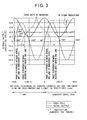
- FIG. 3 is a view showing the depth (height) of groove and the change in the corresponding phase for a total output signal of the photo-detector used for information reproduction (indicated by the solid line in FIG. 3) and a push pull signal used for the tracking servo control (indicated by the broken line in FIG.
- FIG. 3 reveals the structure of the optical disc DK, in which the material of the recording layer 3 is cyanine organic dye, the depth of groove G being 100 nm, the thickness of the recording layer 3 forming the recording track TR being 100 nm, the thickness of the recording layer 3 formed in the areas opposed to the land L being 40 nm, the width of the recording track TR being 0.16 ⁇ m, and the distance between adjacent recording tracks TR (tracking pitch) being 0.32 ⁇ m.
- the phase in the reflected light of the optical beam for information reproduction is positive before and after the recording process, and changed as shown in the right half part of FIG. 3, because the recording layer in the conventional DVD is convex as seen from the incident side of the optical beam.
- the phase in the reflected light of the optical beam P is negative before and after the recording process, and changed from -315° (unrecorded portion) to -230° (recorded area R), for example, as shown in the left half part of FIG. 3, because the recording layer 3 is concave as seen from the incident side of the optical beam P (see FIG. 1). And this change of phase corresponds to a degree of modulation for the RF (Radio Frequency) signal when reproducing the information.
- RF Radio Frequency
- the information recording apparatus S of the embodiment comprises a pickup 10 as a radiating device, a driver 11 as a modulating device, an encoder 12 as an encoding device, a formatter 13, a multiplexer 14, the A/D converters 15 and 16, a controller 17, and a servo controller 18.
- the music information Sain input via a audio input terminal AIN from the outside is input into an A/D converter 15, digitized in the A/D converter 15, and output as the digital music information Sda to the multiplexer 14.
- the image information Svin input via an image input terminal VIN from the outside is input into an A/D converter 16, digitized in the A/D converter 16, and output as the digital image information Sdv to the multiplexer 14.
- the multiplexer 14 synthesizes the digital music information Sda and the digital image information Sdv into the synthesis information Smx, which is then output to the formatter 13 and the controller 17.
- the controller 17 generates the control information (generally referred to as the navigation information) for controlling the way of reproduction in reproducing the above-cited information from the optical disc DK, based on the synthesis information Smx, and outputs the control information Snv to the formatter 13.
- the control information generally referred to as the navigation information
- the formatter 13 superimposes the control information Snv on the music information and image information input as the synthesis information Smx in accordance with a standardized format, and outputs the superimposed information Sf to the encoder 12.
- the encoder 12 encodes the superimposed information Sf, in which a recording signal Se for recording the superimposed information Sf on the optical disc DK is generated by modulating the intensity of optical beam B emitted from the pickup 10 based on the encoded superimposed signal Sf and output to the driver 11.
- the driver 11 generates a drive signal Sr for driving a semiconductor laser, not shown, within the pickup 10, based on the recording signal Se, and outputs the drive signal Sr to the semiconductor laser.
- the semiconductor laser modulates the intensity of optical beam B in accordance with the content of the drive signal Sr, and emits the optical beam B to the recording track TR of object on the optical disc DK.
- the recorded area R recording pit of which the reflectance is changed corresponding to the content of the drive signal Sr within the recording track TR is formed, whereby the music information Sain and the image information Svin are recorded on the optical disc DK.
- the vertical position of optical beam B applied (i.e., converged position of optical beam B) is controlled by driving a focus actuator, not shown, within the pickup 10, based on a control signal Ssp from the servo controller 18, while the horizontal position of optical beam B applied is controlled by driving a tracking actuator, not shown, within the pickup 10.
- the spindle motor 19 controls the rotation of the optical disc DK so that the preset rotation number may be reached, based on a control signal Sss from the servo controller 18.
- the servo controller 18 generates and outputs the control signals Sss and Ssp, based on a control signal Scc from the controller 17.
- the recording track TR is formed concave on the substrate 1 as seen from the side of the cover layer 5 on which the optical beam B is incident, so that the thickness of the recording layer 3 forming the recording track TR is greater than the thickness of the recording layer 3 formed in the area opposed to the land L. Therefore, the recording interference, which may occur between adjacent recording tracks TR when a part of the optical beam P is applied on the area other than the recording track TR, has less influence on the information reproduction, making itpossible to narrow the interval between adjacent recording tracks TR and increase the recording density of information in the optical disc DK.
- the recording layer 3 is formed, employing the spin coat method, there is less influence of recording interference on the optical disc DK having the recording layer 3 formed by the spin coat method, thereby narrowing the interval between adjacent recording tracks TR and increasing the recording density of information.
- the depth of groove G in the substrate 1 and the thickness of the recording layer 3 forming the recording track TR are set up such that -360° ⁇ 0 , ⁇ 1 ⁇ -180°, and ⁇ 0 ⁇ 1 whereby the influence of recording interference between adjacent recording tracks TR caused by applying a part of the optical beam P in the area other than the recording track TR on the information reproduction is further reduced.
- the music information Sain to be recorded is encoded to generate the recording information Se
- the optical beam B is modulated based on the recording information Se
- the modulated optical beam B is applied in the recording track TR to record the information, whereby there is less influence of recording interference between adjacent recording tracks TR in recording the information, thereby narrowing the interval between adjacent recording tracks TR and increasing the recording density of information to record the information.
- Figure 5 shows the experimental results concerning the influence of recording pits on adjacent recording tracks on the reproducing signal when the conventional DVD is directly employed for recording the information by the optical beam incident from the side of the cover layer ( Figure 5B), and the influence of recording pits (recorded area R) on adjacent recording tracks TR on the reproducing signal when the optical disc DK of this embodiment is employed for recording the information by the optical beam B incident from the side of the cover layer 5 ( Figure 5A).
- the experimental items for the experimental results as shown in FIG. 5 are as follows.
- the material of the recording layer 3 is cyanine organic dye
- the depth of groove G is 100 nm
- the thickness of the recording layer 3 forming the recording track TR is 100 nm
- the thickness of the recording layer 3 in the area opposed to the land L is 40 nm
- the reflectance of the overall optical disc DK is 37.6%
- the width of recording track TR is 0.16 ⁇ m
- the distance (track pitch) between adjacent recording tracks TR is 0.32 ⁇ m
- the reflectance of the substrate 1 is 1.63+0.00i
- the reflectance of the reflecting layer 2 is 0.30+3.62i
- the reflectance of the recording layer 3 is 1.99+0.05i
- the reflectance of the protective layer 4 is 2.31+0.00i
- the reflectance of the cover layer 5 is 1.63+0.00i, in which the modulation ratio is 0.805.
- the thickness of the recording layer is almost equivalent between the position opposed to the recording track and the position opposed to the land in the case of FIG. 5B, whereby the recording pits on the adjacent recording tracks have great influence on the reproducing signal. That is, the recorded area formed in the recording tracks adjacent to the recording track of reproduction object and the area between recording tracks (area opposed to the land) has great influence on the reproducing signal obtained from the recording track, so that more noise may be contained in the reproducing signal.
Landscapes
- Optical Recording Or Reproduction (AREA)
- Optical Record Carriers And Manufacture Thereof (AREA)
Applications Claiming Priority (3)
| Application Number | Priority Date | Filing Date | Title |
|---|---|---|---|
| JP2002201620 | 2002-07-10 | ||
| JP2002201620 | 2002-07-10 | ||
| PCT/JP2003/006853 WO2004008442A1 (ja) | 2002-07-10 | 2003-05-30 | 情報記録媒体及び情報記録装置 |
Publications (2)
| Publication Number | Publication Date |
|---|---|
| EP1548709A1 true EP1548709A1 (de) | 2005-06-29 |
| EP1548709A4 EP1548709A4 (de) | 2008-05-07 |
Family
ID=30112582
Family Applications (1)
| Application Number | Title | Priority Date | Filing Date |
|---|---|---|---|
| EP03733195A Withdrawn EP1548709A4 (de) | 2002-07-10 | 2003-05-30 | Informationsaufzeichnungsmedium und informationsaufzeichnungsvorrichtung |
Country Status (6)
| Country | Link |
|---|---|
| US (1) | US7551831B2 (de) |
| EP (1) | EP1548709A4 (de) |
| JP (1) | JPWO2004008442A1 (de) |
| CN (1) | CN1666263A (de) |
| AU (1) | AU2003241996A1 (de) |
| WO (1) | WO2004008442A1 (de) |
Families Citing this family (2)
| Publication number | Priority date | Publication date | Assignee | Title |
|---|---|---|---|---|
| JP4264532B2 (ja) * | 2002-11-19 | 2009-05-20 | ソニー株式会社 | ディスク基板および光ディスク |
| JP4660217B2 (ja) | 2005-01-31 | 2011-03-30 | 株式会社東芝 | 記憶媒体、再生方法、記録方法、再生装置及び記録装置 |
Family Cites Families (9)
| Publication number | Priority date | Publication date | Assignee | Title |
|---|---|---|---|---|
| JP2541847B2 (ja) | 1989-01-11 | 1996-10-09 | 日本ビクター株式会社 | 光学的記録媒体円盤 |
| JP2839062B2 (ja) | 1993-03-30 | 1998-12-16 | 太陽誘電株式会社 | 書き込み可能な光情報記録媒体 |
| KR20000064320A (ko) | 1996-09-03 | 2000-11-06 | 요트.게.아. 롤페즈 | 정보 블록의 기록 및 판독용 정보매체, 판독/기록장치와 판독장치 |
| JPH10340483A (ja) | 1997-06-07 | 1998-12-22 | Ricoh Co Ltd | 光情報記録媒体とその記録/再生方法 |
| EP1132901A3 (de) * | 2000-02-16 | 2001-11-28 | Fuji Photo Film Co., Ltd. | Informationsaufzeichnungsmedium und Aufzeichnungsverfahren |
| JP2002008269A (ja) | 2000-06-22 | 2002-01-11 | Sony Corp | 光学記録媒体およびその製造方法 |
| JP2002093047A (ja) * | 2000-09-20 | 2002-03-29 | Sony Corp | データ記録媒体、データ記録装置および方法、データ出力装置および方法、データ表示方法、コンテンツデータ並びにデータ再生装置および方法 |
| JP2003109246A (ja) | 2000-09-29 | 2003-04-11 | Matsushita Electric Ind Co Ltd | 光ディスクとその作製方法 |
| JP2003263779A (ja) | 2002-03-08 | 2003-09-19 | Fuji Photo Film Co Ltd | 光情報記録媒体及びその製造方法 |
-
2003
- 2003-05-30 EP EP03733195A patent/EP1548709A4/de not_active Withdrawn
- 2003-05-30 AU AU2003241996A patent/AU2003241996A1/en not_active Abandoned
- 2003-05-30 WO PCT/JP2003/006853 patent/WO2004008442A1/ja not_active Ceased
- 2003-05-30 JP JP2004521127A patent/JPWO2004008442A1/ja active Pending
- 2003-05-30 CN CN03816231.8A patent/CN1666263A/zh active Pending
- 2003-05-30 US US10/520,665 patent/US7551831B2/en not_active Expired - Fee Related
Also Published As
| Publication number | Publication date |
|---|---|
| EP1548709A4 (de) | 2008-05-07 |
| CN1666263A (zh) | 2005-09-07 |
| JPWO2004008442A1 (ja) | 2005-11-10 |
| WO2004008442A1 (ja) | 2004-01-22 |
| US7551831B2 (en) | 2009-06-23 |
| US20050254795A1 (en) | 2005-11-17 |
| AU2003241996A1 (en) | 2004-02-02 |
Similar Documents
| Publication | Publication Date | Title |
|---|---|---|
| US6795389B1 (en) | Optical information recording medium with substrate and multiple information | |
| US7215620B2 (en) | Information recording medium with management area having recording identification information | |
| US8009547B2 (en) | Optical recording and reproducing apparatus capable of identifying the type of optical disc based on reflectance, and reproducing method for optical disc | |
| US20030081536A1 (en) | Information record medium with a record/reproduction area and a reproduction-dedicated area | |
| EP0871162B1 (de) | Verfahren zur Auzeichnung eines Phasenwechselaufzeichnungsmediums für Spurführung nach dem differentiellen Phasendetekttionsverfahren | |
| EP1189213B1 (de) | Optisches Aufzeichnungsmedium, Vorrichtung dafür und Verfahren zur Herstellung desselben | |
| EP0414429A2 (de) | Optische Platte | |
| US4872156A (en) | Record carrier with a preformed information track for recording information with a radiation beam | |
| US6930969B2 (en) | Optical recording medium applicable for improved servo control | |
| US6295270B1 (en) | Optical record carrier with grooves having wobbles with phases depending on position information pits at predetermined positions | |
| EP1202255A2 (de) | Mehrschichtiges Informationsaufzeichnungsmedium und Aufzeichnungsgerät dafür | |
| US6687214B2 (en) | Recording medium and apparatus and method for manufacturing the same | |
| US20020039346A1 (en) | Optical disc and method for manufacturing the optical disc | |
| EP1126444A2 (de) | Optisches Speichermedium und Matrizenplatte zur Herstellung desselben | |
| US7551831B2 (en) | Information recording medium and information recorder | |
| JP4594092B2 (ja) | 記録スタック型式インジケータを有するマルチレイヤ光ディスク | |
| MXPA05010078A (es) | Control de potencia optima para discos opticos de capas multiples. | |
| EP0944045A2 (de) | Optisches Plattengerät zum Wiedergaben von Information durch Verschieben der Lichtstrahlposition weg vom Zentrum der Preformatierungspitanordnung einer optischen Platte | |
| KR20050024448A (ko) | 정보 기록 매체 및 정보 기록 장치 | |
| EP1581935B1 (de) | Zusätzlicher datenkanal in der spurrille | |
| KR100386040B1 (ko) | 광기록매체 | |
| KR20070005585A (ko) | 결합된 rom/r 영역을 갖는 광학 디스크 | |
| JP2006134393A (ja) | バーストカッティングエリアの記録方法及び光ディスク | |
| JP2002109788A (ja) | 光ディスク及び光ディスク装置 | |
| JPH04368629A (ja) | 情報記録媒体 |
Legal Events
| Date | Code | Title | Description |
|---|---|---|---|
| PUAI | Public reference made under article 153(3) epc to a published international application that has entered the european phase |
Free format text: ORIGINAL CODE: 0009012 |
|
| 17P | Request for examination filed |
Effective date: 20050120 |
|
| AK | Designated contracting states |
Kind code of ref document: A1 Designated state(s): AT BE BG CH CY CZ DE DK EE ES FI FR GB GR HU IE IT LI LU MC NL PT RO SE SI SK TR |
|
| AX | Request for extension of the european patent |
Extension state: AL LT LV MK |
|
| DAX | Request for extension of the european patent (deleted) | ||
| A4 | Supplementary search report drawn up and despatched |
Effective date: 20080407 |
|
| 17Q | First examination report despatched |
Effective date: 20080707 |
|
| STAA | Information on the status of an ep patent application or granted ep patent |
Free format text: STATUS: THE APPLICATION HAS BEEN WITHDRAWN |
|
| 18W | Application withdrawn |
Effective date: 20100302 |