EP1548696B1 - Verfahren und Vorrichtung zur Ansteuerung einer Plasmaanzeige - Google Patents
Verfahren und Vorrichtung zur Ansteuerung einer Plasmaanzeige Download PDFInfo
- Publication number
- EP1548696B1 EP1548696B1 EP04029331A EP04029331A EP1548696B1 EP 1548696 B1 EP1548696 B1 EP 1548696B1 EP 04029331 A EP04029331 A EP 04029331A EP 04029331 A EP04029331 A EP 04029331A EP 1548696 B1 EP1548696 B1 EP 1548696B1
- Authority
- EP
- European Patent Office
- Prior art keywords
- video data
- inverse gamma
- gamma correction
- dither
- value
- Prior art date
- Legal status (The legal status is an assumption and is not a legal conclusion. Google has not performed a legal analysis and makes no representation as to the accuracy of the status listed.)
- Expired - Lifetime
Links
- 238000000034 method Methods 0.000 title claims description 43
- 238000009792 diffusion process Methods 0.000 claims description 113
- 241001270131 Agaricus moelleri Species 0.000 claims description 37
- 238000013507 mapping Methods 0.000 claims description 10
- 230000004044 response Effects 0.000 claims description 2
- 239000010410 layer Substances 0.000 description 12
- 238000010586 diagram Methods 0.000 description 7
- 230000000694 effects Effects 0.000 description 6
- 239000000758 substrate Substances 0.000 description 5
- OAICVXFJPJFONN-UHFFFAOYSA-N Phosphorus Chemical compound [P] OAICVXFJPJFONN-UHFFFAOYSA-N 0.000 description 4
- 239000007789 gas Substances 0.000 description 4
- 230000004888 barrier function Effects 0.000 description 3
- 238000007599 discharging Methods 0.000 description 3
- 238000003672 processing method Methods 0.000 description 2
- 239000003086 colorant Substances 0.000 description 1
- 230000003247 decreasing effect Effects 0.000 description 1
- 230000009977 dual effect Effects 0.000 description 1
- 239000002355 dual-layer Substances 0.000 description 1
- 239000011261 inert gas Substances 0.000 description 1
- 239000002184 metal Substances 0.000 description 1
- 239000002245 particle Substances 0.000 description 1
- 238000013139 quantization Methods 0.000 description 1
- 238000000926 separation method Methods 0.000 description 1
- 238000004544 sputter deposition Methods 0.000 description 1
- 230000002123 temporal effect Effects 0.000 description 1
- 230000000007 visual effect Effects 0.000 description 1
Images


Classifications
-
- G—PHYSICS
- G09—EDUCATION; CRYPTOGRAPHY; DISPLAY; ADVERTISING; SEALS
- G09G—ARRANGEMENTS OR CIRCUITS FOR CONTROL OF INDICATING DEVICES USING STATIC MEANS TO PRESENT VARIABLE INFORMATION
- G09G3/00—Control arrangements or circuits, of interest only in connection with visual indicators other than cathode-ray tubes
- G09G3/20—Control arrangements or circuits, of interest only in connection with visual indicators other than cathode-ray tubes for presentation of an assembly of a number of characters, e.g. a page, by composing the assembly by combination of individual elements arranged in a matrix no fixed position being assigned to or needed to be assigned to the individual characters or partial characters
- G09G3/22—Control arrangements or circuits, of interest only in connection with visual indicators other than cathode-ray tubes for presentation of an assembly of a number of characters, e.g. a page, by composing the assembly by combination of individual elements arranged in a matrix no fixed position being assigned to or needed to be assigned to the individual characters or partial characters using controlled light sources
- G09G3/28—Control arrangements or circuits, of interest only in connection with visual indicators other than cathode-ray tubes for presentation of an assembly of a number of characters, e.g. a page, by composing the assembly by combination of individual elements arranged in a matrix no fixed position being assigned to or needed to be assigned to the individual characters or partial characters using controlled light sources using luminous gas-discharge panels, e.g. plasma panels
- G09G3/288—Control arrangements or circuits, of interest only in connection with visual indicators other than cathode-ray tubes for presentation of an assembly of a number of characters, e.g. a page, by composing the assembly by combination of individual elements arranged in a matrix no fixed position being assigned to or needed to be assigned to the individual characters or partial characters using controlled light sources using luminous gas-discharge panels, e.g. plasma panels using AC panels
- G09G3/291—Control arrangements or circuits, of interest only in connection with visual indicators other than cathode-ray tubes for presentation of an assembly of a number of characters, e.g. a page, by composing the assembly by combination of individual elements arranged in a matrix no fixed position being assigned to or needed to be assigned to the individual characters or partial characters using controlled light sources using luminous gas-discharge panels, e.g. plasma panels using AC panels controlling the gas discharge to control a cell condition, e.g. by means of specific pulse shapes
- G09G3/293—Control arrangements or circuits, of interest only in connection with visual indicators other than cathode-ray tubes for presentation of an assembly of a number of characters, e.g. a page, by composing the assembly by combination of individual elements arranged in a matrix no fixed position being assigned to or needed to be assigned to the individual characters or partial characters using controlled light sources using luminous gas-discharge panels, e.g. plasma panels using AC panels controlling the gas discharge to control a cell condition, e.g. by means of specific pulse shapes for address discharge
- G09G3/2932—Addressed by writing selected cells that are in an OFF state
-
- G—PHYSICS
- G09—EDUCATION; CRYPTOGRAPHY; DISPLAY; ADVERTISING; SEALS
- G09G—ARRANGEMENTS OR CIRCUITS FOR CONTROL OF INDICATING DEVICES USING STATIC MEANS TO PRESENT VARIABLE INFORMATION
- G09G3/00—Control arrangements or circuits, of interest only in connection with visual indicators other than cathode-ray tubes
- G09G3/20—Control arrangements or circuits, of interest only in connection with visual indicators other than cathode-ray tubes for presentation of an assembly of a number of characters, e.g. a page, by composing the assembly by combination of individual elements arranged in a matrix no fixed position being assigned to or needed to be assigned to the individual characters or partial characters
- G09G3/2007—Display of intermediate tones
- G09G3/2018—Display of intermediate tones by time modulation using two or more time intervals
- G09G3/2022—Display of intermediate tones by time modulation using two or more time intervals using sub-frames
-
- G—PHYSICS
- G09—EDUCATION; CRYPTOGRAPHY; DISPLAY; ADVERTISING; SEALS
- G09G—ARRANGEMENTS OR CIRCUITS FOR CONTROL OF INDICATING DEVICES USING STATIC MEANS TO PRESENT VARIABLE INFORMATION
- G09G3/00—Control arrangements or circuits, of interest only in connection with visual indicators other than cathode-ray tubes
- G09G3/20—Control arrangements or circuits, of interest only in connection with visual indicators other than cathode-ray tubes for presentation of an assembly of a number of characters, e.g. a page, by composing the assembly by combination of individual elements arranged in a matrix no fixed position being assigned to or needed to be assigned to the individual characters or partial characters
- G09G3/2007—Display of intermediate tones
- G09G3/2044—Display of intermediate tones using dithering
- G09G3/2051—Display of intermediate tones using dithering with use of a spatial dither pattern
- G09G3/2055—Display of intermediate tones using dithering with use of a spatial dither pattern the pattern being varied in time
-
- G—PHYSICS
- G09—EDUCATION; CRYPTOGRAPHY; DISPLAY; ADVERTISING; SEALS
- G09G—ARRANGEMENTS OR CIRCUITS FOR CONTROL OF INDICATING DEVICES USING STATIC MEANS TO PRESENT VARIABLE INFORMATION
- G09G3/00—Control arrangements or circuits, of interest only in connection with visual indicators other than cathode-ray tubes
- G09G3/20—Control arrangements or circuits, of interest only in connection with visual indicators other than cathode-ray tubes for presentation of an assembly of a number of characters, e.g. a page, by composing the assembly by combination of individual elements arranged in a matrix no fixed position being assigned to or needed to be assigned to the individual characters or partial characters
- G09G3/2007—Display of intermediate tones
- G09G3/2077—Display of intermediate tones by a combination of two or more gradation control methods
-
- G—PHYSICS
- G09—EDUCATION; CRYPTOGRAPHY; DISPLAY; ADVERTISING; SEALS
- G09G—ARRANGEMENTS OR CIRCUITS FOR CONTROL OF INDICATING DEVICES USING STATIC MEANS TO PRESENT VARIABLE INFORMATION
- G09G3/00—Control arrangements or circuits, of interest only in connection with visual indicators other than cathode-ray tubes
- G09G3/20—Control arrangements or circuits, of interest only in connection with visual indicators other than cathode-ray tubes for presentation of an assembly of a number of characters, e.g. a page, by composing the assembly by combination of individual elements arranged in a matrix no fixed position being assigned to or needed to be assigned to the individual characters or partial characters
- G09G3/22—Control arrangements or circuits, of interest only in connection with visual indicators other than cathode-ray tubes for presentation of an assembly of a number of characters, e.g. a page, by composing the assembly by combination of individual elements arranged in a matrix no fixed position being assigned to or needed to be assigned to the individual characters or partial characters using controlled light sources
- G09G3/28—Control arrangements or circuits, of interest only in connection with visual indicators other than cathode-ray tubes for presentation of an assembly of a number of characters, e.g. a page, by composing the assembly by combination of individual elements arranged in a matrix no fixed position being assigned to or needed to be assigned to the individual characters or partial characters using controlled light sources using luminous gas-discharge panels, e.g. plasma panels
- G09G3/288—Control arrangements or circuits, of interest only in connection with visual indicators other than cathode-ray tubes for presentation of an assembly of a number of characters, e.g. a page, by composing the assembly by combination of individual elements arranged in a matrix no fixed position being assigned to or needed to be assigned to the individual characters or partial characters using controlled light sources using luminous gas-discharge panels, e.g. plasma panels using AC panels
- G09G3/291—Control arrangements or circuits, of interest only in connection with visual indicators other than cathode-ray tubes for presentation of an assembly of a number of characters, e.g. a page, by composing the assembly by combination of individual elements arranged in a matrix no fixed position being assigned to or needed to be assigned to the individual characters or partial characters using controlled light sources using luminous gas-discharge panels, e.g. plasma panels using AC panels controlling the gas discharge to control a cell condition, e.g. by means of specific pulse shapes
- G09G3/293—Control arrangements or circuits, of interest only in connection with visual indicators other than cathode-ray tubes for presentation of an assembly of a number of characters, e.g. a page, by composing the assembly by combination of individual elements arranged in a matrix no fixed position being assigned to or needed to be assigned to the individual characters or partial characters using controlled light sources using luminous gas-discharge panels, e.g. plasma panels using AC panels controlling the gas discharge to control a cell condition, e.g. by means of specific pulse shapes for address discharge
- G09G3/2935—Addressed by erasing selected cells that are in an ON state
-
- G—PHYSICS
- G09—EDUCATION; CRYPTOGRAPHY; DISPLAY; ADVERTISING; SEALS
- G09G—ARRANGEMENTS OR CIRCUITS FOR CONTROL OF INDICATING DEVICES USING STATIC MEANS TO PRESENT VARIABLE INFORMATION
- G09G3/00—Control arrangements or circuits, of interest only in connection with visual indicators other than cathode-ray tubes
- G09G3/20—Control arrangements or circuits, of interest only in connection with visual indicators other than cathode-ray tubes for presentation of an assembly of a number of characters, e.g. a page, by composing the assembly by combination of individual elements arranged in a matrix no fixed position being assigned to or needed to be assigned to the individual characters or partial characters
- G09G3/22—Control arrangements or circuits, of interest only in connection with visual indicators other than cathode-ray tubes for presentation of an assembly of a number of characters, e.g. a page, by composing the assembly by combination of individual elements arranged in a matrix no fixed position being assigned to or needed to be assigned to the individual characters or partial characters using controlled light sources
- G09G3/28—Control arrangements or circuits, of interest only in connection with visual indicators other than cathode-ray tubes for presentation of an assembly of a number of characters, e.g. a page, by composing the assembly by combination of individual elements arranged in a matrix no fixed position being assigned to or needed to be assigned to the individual characters or partial characters using controlled light sources using luminous gas-discharge panels, e.g. plasma panels
- G09G3/288—Control arrangements or circuits, of interest only in connection with visual indicators other than cathode-ray tubes for presentation of an assembly of a number of characters, e.g. a page, by composing the assembly by combination of individual elements arranged in a matrix no fixed position being assigned to or needed to be assigned to the individual characters or partial characters using controlled light sources using luminous gas-discharge panels, e.g. plasma panels using AC panels
- G09G3/296—Driving circuits for producing the waveforms applied to the driving electrodes
-
- G—PHYSICS
- G09—EDUCATION; CRYPTOGRAPHY; DISPLAY; ADVERTISING; SEALS
- G09G—ARRANGEMENTS OR CIRCUITS FOR CONTROL OF INDICATING DEVICES USING STATIC MEANS TO PRESENT VARIABLE INFORMATION
- G09G2320/00—Control of display operating conditions
- G09G2320/02—Improving the quality of display appearance
- G09G2320/0238—Improving the black level
-
- G—PHYSICS
- G09—EDUCATION; CRYPTOGRAPHY; DISPLAY; ADVERTISING; SEALS
- G09G—ARRANGEMENTS OR CIRCUITS FOR CONTROL OF INDICATING DEVICES USING STATIC MEANS TO PRESENT VARIABLE INFORMATION
- G09G2320/00—Control of display operating conditions
- G09G2320/02—Improving the quality of display appearance
- G09G2320/0266—Reduction of sub-frame artefacts
-
- G—PHYSICS
- G09—EDUCATION; CRYPTOGRAPHY; DISPLAY; ADVERTISING; SEALS
- G09G—ARRANGEMENTS OR CIRCUITS FOR CONTROL OF INDICATING DEVICES USING STATIC MEANS TO PRESENT VARIABLE INFORMATION
- G09G2320/00—Control of display operating conditions
- G09G2320/02—Improving the quality of display appearance
- G09G2320/0271—Adjustment of the gradation levels within the range of the gradation scale, e.g. by redistribution or clipping
- G09G2320/0276—Adjustment of the gradation levels within the range of the gradation scale, e.g. by redistribution or clipping for the purpose of adaptation to the characteristics of a display device, i.e. gamma correction
-
- G—PHYSICS
- G09—EDUCATION; CRYPTOGRAPHY; DISPLAY; ADVERTISING; SEALS
- G09G—ARRANGEMENTS OR CIRCUITS FOR CONTROL OF INDICATING DEVICES USING STATIC MEANS TO PRESENT VARIABLE INFORMATION
- G09G3/00—Control arrangements or circuits, of interest only in connection with visual indicators other than cathode-ray tubes
- G09G3/20—Control arrangements or circuits, of interest only in connection with visual indicators other than cathode-ray tubes for presentation of an assembly of a number of characters, e.g. a page, by composing the assembly by combination of individual elements arranged in a matrix no fixed position being assigned to or needed to be assigned to the individual characters or partial characters
- G09G3/2007—Display of intermediate tones
- G09G3/2059—Display of intermediate tones using error diffusion
Definitions
- the present invention relates to a method and apparatus for driving a plasma display panel, and more particularly, to a method and apparatus for driving a plasma display panel in which signal distortion can be minimized while reducing contour noise.
- EP 1 262 947 A1 discloses a method utilising different dither patterns for different entries in a number of least significant bits of the data word representing the input video level. Thereby disturbing patterns can be suppressed.
- US 6 476 824 B1 shows a luminance enhancement circuit generating dither signals responsive to spatial and temporal coordinates of a pixel and a calculated average value according to a non-displayable component of the image signal.
- EP 1 022 714 A2 shows a method for driving a plasma display panel with an improved expression of levels of halftone as well as an improved display quality. The light emission period in the light emission sustaining step of sub-fields is changed field by field or frame by frame. According to another aspect a first or a second drive pattern can be carried out.
- a plasma display panel (hereinafter, referred to as 'PDP'), which can be easily made large, has attracted public attention as a flat panel display device.
- the PDP is adapted to display an image by controlling a gas discharge period of each of pixels according to digital video data.
- a representative PDP is one, which has three electrodes and is driven with an AC voltage, as shown in FIG. 1.
- FIG.1 is a perspective view illustrating the structure of a discharge cell of a conventional three-electrode AC surface discharge type PDP.
- the discharge cell of the PDP includes a pair of sustain electrodes 12A, 12B formed on the bottom surface of an upper substrate 10, and a data electrode 20 formed on the top surface of a lower substrate 18.
- Each of the pair of the sustain electrodes 12A, 12B has a dual layer structure of transparent electrodes and metal electrodes.
- the sustain electrode pair 12A, 12B include a scan electrode 12A which receives a scan signal for an address discharge and a sustain signal for a sustain discharge as an input, and a sustain electrode 12B which receives a sustain signal, while operating in turn with the scan electrode 12A.
- the data electrode 20 is formed in such a way to cross the pair of the sustain electrodes 12A, 12B, and supplies a data signal for the address discharge.
- An upper dielectric layer 14 and a protection film 16 are laminated on the upper substrate 10 on which the pair of the sustain electrodes 12A, 12B is formed.
- a lower dielectric layer 22 is formed on the lower substrate 18 on which the data electrode 20 is formed.
- the upper dielectric layer 14 and the lower dielectric layer 22 serve to accumulate electric charges generated by discharging.
- the protection film 16 serves to prevent damage of the upper dielectric layer 14 due to sputtering of plasma particles upon discharging, and improve emission efficiency of secondary electrons.
- the dielectric layers 14, 22 and the protection film 16 serve to low an externally inputted driving voltage.
- Barrier ribs 24 are formed over the lower substrate 18 on which the lower dielectric layer 22 is formed.
- a phosphor layer 26 is formed on the lower dielectric layer 22 and the barrier ribs 24.
- the barrier ribs 24 serve to separate discharge spaces and to prevent ultraviolet generated by a gas discharge from leaking toward neighboring discharge spaces.
- the phosphor layer 26 is light-emitted by the ultraviolet generated by the gas discharge, producing red (R), green (G) and blue (B) visible rays. Also, an inert gas for the gas discharge is injected into the discharge spaces.
- This discharge cell is selected according to the address discharge by the data electrode 20 and the scan electrode 12A.
- the selected discharge cell sustains its discharge with a sustain discharge by the pair of the sustain electrodes 12A, 12B.
- the discharge cell emits the phosphor layer 26 with the ultraviolet generated in the sustain discharge, so that the phosphor layer 26 emits the R, G and B visible rays.
- the discharge cell implements the gray scale necessary for image display by controlling a sustain discharge period, i.e., the number of sustain discharges according to video data.
- a combination of three discharge cells on which the R, G and B phosphors 26 are respectively coated implements the colors of one pixel.
- a representative method for driving this PDP is an ADS (Address and Display Separation) driving method in which the PDP is driven with one frame being divided into an address period and a display period, i.e., a sustain period.
- ADS driving method one frame 1F is divided into a plurality of sub-fields SF1 to SF8 corresponding to respective bits of video data.
- Each of the sub-fields SF1 to SF8 is subdivided into a reset period RPD for initializing a discharge cell, an address period APD for selecting a discharge cell, and a sustain period SPD for maintaining discharging of a selected discharge cell.
- the PDP implements a corresponding gray scale in such a way that a different weight is assigned to the sustain periods SPD every sub-fields SF1 to SF8, and the sustain periods SPD are combined according to the video data.
- This method of driving the PDP is mainly classified into a selective writing mode and a selective erasing mode depending upon whether a discharge cell selected by an address discharge is light-emitted.
- the whole screen is turned off in the reset period, and selected discharge cells are then turned on in the address period.
- the sustain period discharge of the discharge cells selected by the address discharge is maintained.
- a width of a scan pulse is set to be relatively wide (for example, 3 ⁇ s), so that sufficient wall charges are formed within the discharge cells. If the width of the scan pulse is set to be wide, however, a problem arises in that the address period is set to be wide and the sustain period, which contributes to the brightness, is set to be relatively narrow.
- the width of the scan pulse is set to be relatively narrow (for example, ⁇ s), so that an erase discharge is generated in the discharge cells. That is, in the selective erasing mode, the address period can be set to be short by applying the scan pulse having the narrow width. Accordingly, relatively lots of time can be allocated to the sustain period, which contributes to the brightness.
- the selective erasing mode is disadvantageous in that contrast is low because the whole screen is turned on in the reset period being a non-display period.
- contour noise arises due to mismatch between the integral direction of light, which is assumed in the PDP, and a visual characteristic, which is recognized by the eye of a man.
- contour noise increases when it has consecutive gray scales such as when the skin of a man is being displayed. For example, if gray scales light-emitted patterns of which are significantly different such as 127-128, 63-64 gray scale, 31-32 gray scale, etc. are displayed consecutively, contour noise increases.
- quantization error data of digital video data is calculated using a Floyd-Steinberg error diffusion filter, etc., the calculated error data is assigned with a different weight and are then diffused to neighboring pixels.
- error diffusion coefficients i.e., weight
- this method has a problem in that an error diffusion pattern occurs due to the constant error diffusion coefficients.
- the dithering method includes adding adequate noise so that contour noise is unnoticeable to the eye of a man.
- European Patent Application No.00250099.9 discloses a method in which three-dimensional dither patterns corresponding to a plurality of frames, a plurality of lines and a plurality of columns are repeatedly used in a PDP.
- the conventional dithering method has a problem in that dithering noise occurs, which degrades the picture quality in specific gray scales.
- three-dimensional dither patterns are repeatedly used while toggling them, in spite of low gray scales and high gray scales. Therefore, there occurs a problem such as flicker when representing the low gray scales.
- the present invention has been made in view of the above problems, and it is an object of the present invention to provide a method and apparatus for driving a plasma display panel in which signal distortion can be minimized while reducing contour noise, according to the annexed set of claims.
- FJG.1 is a perspective view illustrating the structure of a discharge cell of a conventional three-electrode AC surface discharge type PDP;
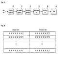
- FIG. 2 is a view showing one frame of the conventional PDP
- FIG. 3 is a view showing one frame of a PDP according to an embodiment of the present invention.
- FIG. 4 is a block diagram of an apparatus for driving a PDP according to an embodiment of the present invention.
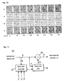
- FIG. 5 shows a data format outputted from the first gamma correction unit shown in FIG. 4;
- FIG. 6 is a detailed block diagram of the error diffusion and dithering unit shown in FIG. 4;
- FIG. 7 is a detailed block diagram of the confined error diffusion unit shown in FIG. 6;
- FIGS. 8 and 9 are views for explaining an error diffusion method of the confined error diffusion filter shown in FIG. 7;
- FIG. 10 is an example of dither mask patterns which are used for the dithering unit shown in FIG. 6;
- FIG. 11 is a detailed block diagram of the dithering unit shown in FIG. 6;
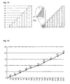
- FIG. 12 is a graph illustrating gray scales which are implemented by dithering among a video data processing method according to an embodiment of the present invention.
- FIG. 13 is a graph illustrating gray scales which are implemented by a confined error diffusion method and a dithering method among a video data processing method according to an embodiment of the present invention.
- a method of driving a plasma display panel including the steps of: performing a first inverse gamma correction operation on externally inputted video data, performing a confined error diffusion operation on the first inverse gamma corrected video data within a range of a dither mask pattern of an upper gray scale, dithering the confined error diffused video data by using a plurality of dither mask patterns which are separated every gray scale and every frame, performing a second inverse gamma correction operation on the dithered video data, and mapping the second inverse gamma corrected video data to a sub-field pattern in which one frame includes one or more selective writing sub-fields and one or more selective erasing sub-fields.
- the inverse gamma correction operation is performed by using a gamma value, which is higher than a gamma value in the step of performing the first inverse gamma correction operation.
- the first inverse gamma correction operation step includes performing the inverse gamma correction operation on the externally inputted video data by using 1.1 to 1.2 gamma curves.
- the second inverse gamma correction operation step includes performing the inverse gamma correction operation so that the externally inputted video data is combined with an inverse gamma correction value resulting from the first inverse gamma correction operation step and then undergoes a 2.2 inverse gamma correction operation.
- the first inverse gamma corrected data includes an integer part and a fraction part.
- the number of selective erasing sub-fields included in the one frame is set to be greater than that of selective writing sub-fields included in the one frame.
- the confined error diffusion operation step includes the steps of performing an error diffusion operation on lower bits of the first inverse gamma corrected video data to generate a first carry signal, comparing the first carry signal with a dither value of a position corresponding to the video data in the dither mask pattern of the upper gray scale, thus generating a second carry signal, and adding the second carry signal to upper bits of the video data and outputting the added results.
- the step of generating the first carry signal comprises the step of adding random error diffusion coefficients, which are randomly set.
- the dither mask patterns of the upper gray scales are selected from dither mask patterns corresponding to upper gray scales than gray scales corresponding to bits of some of the first inverse gamma corrected video data in a plurality of dither mask patterns which are previously stored.
- the step of generating the second carry signal includes generating the second carry signal by performing an AND operation on the first carry signal and the selected dither value.
- the dithering step includes the steps of selecting a dither mask pattern of a corresponding gray scale among the plurality of the dither mask patterns by using lower bits of some of the confined error diffused video data, selecting a dither value of a position corresponding to the confined error diffused video data among the selected dither mask pattern, and adding the selected dither value to upper bits of the remaining confined error diffused video data.
- the step of selecting the dither value includes counting each of a vertical sync signal, a horizontal sync signal and a pixel clock signal all of which are inputted externally, and selecting positions corresponding to the confined error diffused video data by using the counted signals.
- the dither value is selected while toggling dither mask patterns of corresponding gray scales, which are different every frame, by using the counted signal of the vertical sync signal.
- an apparatus for driving a plasma display panel including: a first gamma correction unit for performing a first inverse gamma correction operation on externally inputted video data, a confined error diffusion unit for performing a confined error diffusion operation on the first inverse gamma corrected video data within a range of a dither mask pattern of an upper gray scale, a dithering unit for dithering the confined error diffused video data by using a plurality of dither mask patterns which are separated every gray scale and every frame, a second inverse gamma correction unit for performing a second inverse gamma correction operation on the dithered video data, and a sub-field mapping unit for mapping the second inverse gamma corrected video data to a sub-field pattern in which one frame includes one or more selective writing sub-fields and one or more selective erasing sub-fields.
- the second inverse gamma correction unit performs the inverse gamma correction operation by using a gamma value, which is higher than a gamma value in the first inverse gamma correction unit.
- the first inverse gamma correction unit and the second inverse gamma correction unit perform the inverse gamma correction operation so that the total of inverse gamma correction values of the externally inputted video data becomes 2.2 gamma.
- the number of selective erasing sub-fields included in the one frame is set to be greater than that of selective writing sub-fields included in the one frame.
- the confined error diffusion unit includes a dither mask select unit for selecting a dither value of a position corresponding to the first inverse gamma corrected video data from the dither mask pattern of the upper gray scale, and an error diffusion filter for performing an error diffusion operation on the first inverse gamma corrected video data to generate a first carry signal, comparing the first carry signal with the dither value to generate a second carry signal, and adding the second carry signal to the first inverse gamma corrected video data to produce confined error diffused video data.
- the dither mask select unit selects one of dither mask patterns corresponding to upper gray scale than gray scales corresponding to bits of some of the inputted video data in a plurality of dither mask patterns, which is stored in the dithering unit as the dither mask pattern of the upper gray scale.
- the error diffusion filter performs the error diffusion operation on lower bits of some of the first inverse gamma corrected video data to generate the first carry signal, compares the first carry signal and the dither value to generate the second carry signal, and adds the second carry signal to the remaining upper bits of the video data.
- the error diffusion filter performs an AND operation on the first carry signal and the selected dither value to generate the second carry signal.
- the confined error diffusion unit comprises a random error diffusion coefficient generator for generating random error diffusion coefficients, which will be added during the error diffusion operation.
- the dithering unit includes a dither mask table which stores the plurality of the dither mask patterns, selects a dither value corresponding to the confined error diffused video data among the stored dither mask patterns, and outputs the selected dither value, a mask control unit that indicates a position where the dither mask table corresponds to the confined error diffused video data, and an adder for adding the dither value to the confined error diffused video data, and outputting the added results.
- a dither mask table which stores the plurality of the dither mask patterns, selects a dither value corresponding to the confined error diffused video data among the stored dither mask patterns, and outputs the selected dither value
- a mask control unit that indicates a position where the dither mask table corresponds to the confined error diffused video data
- an adder for adding the dither value to the confined error diffused video data, and outputting the added results.
- the dither mask table selects a dither mask pattern of a corresponding gray scale from the plurality of the dither mask patterns by using lower bits of some of the confined error diffused video data, and selects a dither value of a position corresponding to the confined error diffused video data among dither mask patterns which are selected in response to indication of the mask control unit.
- the adder adds the selected dither value to the remaining upper bits of the confined error diffused video data, and outputs the added results.
- the mask control unit counts a vertical sync signal, a horizontal sync signal and a pixel clock signal, respectively, which are received from the outside, and indicates a position corresponding to the confined error diffused video data by using the counted signals.
- the mask control unit controls the dither mask table to select dither mask patterns of corresponding gray scales, which are different every frame, while toggling the frames, by using the counted signal of the vertical sync signal.
- the mask control unit compares the confined error diffused video data with a predetermined reference value, and if the confined error diffused video data is lower than the predetermined reference value, reduces the number of the toggled frames.
- FIG. 3 is a view showing one frame of a plasma display panel according to an embodiment of the present invention.
- one frame of the PDP according to the present embodiment consists of a selective writing sub-field WSF having one or more sub-fields, and a selective erasing sub-field ESF having one or more sub-fields.
- the selective writing sub-field WSF includes m (where, m is a positive integer greater than 0) number of sub-fields SF1 to SFm.
- Each of the first to (m-1)th sub-fields SF1 to SFm-1 except for the mth sub-field SFm is divided into a reset period where a constant amount of wall charges is uniformly formed in cells of the whole screen, a selective writing address period (hereinafter, referred to as 'writing address period') where on-cells are selected by using a write discharge, a sustain period for causing a sustain discharge in the selected on-cell to occur, and an erase period for erasing the wall charges within the cells after the sustain discharge.
- the mth sub-field SFm being the last sub-field of the selective writing sub-field WSF is divided into the reset period, the writing address period and the sustain period.
- the reset period, the writing address period and the erase period of the selective writing sub-field WSF are the same in brightness weight every sub-fields SF1 to SFm, whereas the sustain period thereof can be the same or different in the brightness weight.
- the mth sub-field SFm does not include the erase period. Thus, cells, which are turned on in the mth sub-field SFm, are not erased, but keep turned on.
- the selective erasing sub-field ESF includes n-m (where, n is a positive integer greater than m) number of sub-fields SFm + 1 to SFn.
- Each of the (m + 1)th to nth sub-fields SFm + 1 to SFn is divided into a selective erasing address period (hereinafter, referred to as 'erasing address period') for selecting off-cells by using an erase discharge, and a sustain period for causing a sustain discharge to occur in on-cells.
- the erasing address period is set to be the same, but the sustain period is set to be the same or different depending upon a brightness relative ratio.
- These selective erasing sub-fields ESF represent the gray scales while selecting off-cells corresponding to data. In this case, the selective erasing sub-fields ESF can generate a discharge only in discharge cells, which are turned on in previous sub-fields.
- m number of sub-fields is driven in the selective writing mode, and n-m number of sub-fields is driven in the selective erasing mode, so that the address period can be set to be short and contrast can be also improved.
- one frame includes the selective erasing sub-field having a short scan pulse, a sufficient sustain period can be secured.
- one frame includes the selective erasing sub-field not having the reset period, contrast can be improved.
- the number of the selective erasing sub-fields ESF included in one frame is set to be higher than that of the selective writing sub-fields WSF.
- the selective writing sub-fields WSF can be included in one frame
- the selective erasing sub-fields ESF are used to represent low gray scales
- the selective erasing sub-fields ESF are used to represent high gray scales.
- FIG. 4 is a block diagram of an apparatus for driving a plasma display panel according to an embodiment of the present invention.
- the apparatus for driving the PDP according to the present invention includes a first gamma correction unit 30, an error diffusion and dithering unit 32, a second gamma correction unit 34, a sub-field mapping unit 36 and a data driving unit 38 all of which are connected between an input line and a panel 40.
- the first gamma correction unit 30 receives digital video data on which a gamma correction operation is performed so that it is suitable for a brightness characteristic of a cathode ray tube (CRT), i.e., video data supplied to each of discharge cells constituting the PDP.
- the first gamma correction unit 30 performs an inverse gamma correction operation on the video data by using a predetermined look-up table (LUT) so that the video data confirms to a 1.1 to 1.2 gamma curve.
- LUT look-up table
- each of the video data outputted from the first gamma correction unit 30 is composed of an integer part and a fraction part, as shown in FIG. 5.
- X is "1" or "0".
- the first gamma correction unit 30 outputs 12-bit corrected video data having a 6-bit integer part and a 6-bit fraction part, or 16-bit corrected video data having a 8-bit integer part and a 8-bit fraction part.
- the first gamma correction unit 30 carries out the inverse gamma correction operation by using the 1.1 to 1.2 gamma curve. If the inverse gamma correction operation is performed using the 1.1 to 1.2 gamma curve as such, the capability to represent low gray scales can be improved. The reason will be described in detail as follows. In a conventional PDP, externally inputted video data undergoes the inverse gamma correction operation using the 2.2 gamma curve and then experiences error diffusion and dithering processes. If the inverse gamma correction operation is performed using the 2.2 gamma curve as such, however, there is a problem in that the capability to represent low gray scales is degraded.
- the inverse gamma correction operation is effected using the 1.1 to 1.2 gamma curve.
- data of the low gray scale has an integer part and a fraction part (e.g., 00000001.XXXXXXX)
- the capability to represent the gray scale can be improved.
- the error diffusion and dithering unit 32 performs an error diffusion operation and a dithering operation using dither mask patterns on each of pixel data received from the first gamma correction unit 30, and then outputs pixel data the number of bits is reduced.
- the error diffusion and dithering unit 32 confines the effect of the error diffusion to a gray scale range of upper dither mask patterns, thereby reducing error diffusion noise and dither noise such as flicker. Detailed description on the error diffusion and dithering unit 32 will be given later on.
- the second gamma correction unit 34 performs an inverse gamma correction operation on the data on which the error diffusion operation and the dithering operation are performed. In this time, the second gamma correction unit 34 carries out the inverse gamma correction operation by using a gamma value higher than that in the first gamma correction unit 30. Actually, the second gamma correction unit 34 performs the inverse gamma correction operation on received data by adding the data to an inverse gamma correction value of the first gamma correction unit 30 so that the 2.2 gamma is accomplished. That is, the second gamma correction unit 34 effects the inverse gamma correction operation so that a gamma value of data outputted therefrom become the 2.2 gamma.
- the sub-field mapping unit 36 maps the video data received from the second gamma correction unit 34 to a sub-field pattern, which includes the selective writing sub-field WSF and the selective erasing sub-field ESF of one frame as shown in FIG. 3.
- a sufficient sustain period can be secured and contrast can be also improved.
- the data driving unit 38 latches the data received from the sub-field mapping unit 36, which is separated by the bit according to the sub-field pattern, and supplies the latched data to address electrode lines of the panel 40, on one line basis, every period where one horizontal line is driven.
- the panel 40 displays given image corresponding to the data received from the data driving unit 38.
- FIG. 6 is a detailed block diagram of the error diffusion and dithering unit 32 shown in FIG. 4.
- the error diffusion and dithering unit 32 of the present invention includes a confined error diffusion unit 41 and a dithering unit 50.
- the confined error diffusion unit 41 performs the error diffusion operation on the video data received from the first gamma correction unit 30. In this time, the confined error diffusion unit 41 adds random error diffusion (hereinafter, referred to as 'R-ED') coefficients to the error diffusion operation so as to prevent error diffusion patterns from occurring due to constant error diffusion coefficients. Moreover, the confined error diffusion unit 41 confines the effect of the error diffusion to the range of dither mask patterns of upper gray scales by using the dither mask patterns used in the dithering unit 50.
- 'R-ED' random error diffusion
- the confined error diffusion unit 41 includes an error diffusion filter 42, and a R-ED coefficient generator 44 and a dither mask select unit 46 both of which are connected to the error diffusion filter 42, as shown in FIG. 7.
- the error diffusion filter 42 includes error diffusion operators (not shown) for error diffusion, and a line memory (not shown) for storing some lower bits to be used in the error diffusion among neighboring pixel data, e.g., fraction parts.
- error diffusion filter 42 stores the 8-bit data corresponding to the fraction part among the 16 bits in the line memory so that the 8-bit data is used for the error diffusion operation of neighboring pixels.
- the error diffusion filter 42 reads the fraction parts of the neighboring pixel data, which is stored in the line memory, and assigns a different weight to the fraction parts depending upon locations of their pixels to calculate error diffusion the coefficients.
- the error diffusion filter 42 performs the error diffusion operation by using weights of 1/16, 5/16, 3/16 and 7/16, as shown in FIG. 8.
- the error diffusion filter 42 effects the error diffusion operation by assigning the weight of 1/16 to a fraction part of a pixel P1, the weight of 5/1 6 to a fraction part of a pixel P2, the weight of 3/1 6 to a fraction part of a pixel P3 and the weight of 7/16 to a fraction part of a pixel P4.
- the error diffusion filter 42 then carries out the error diffusion operation by multiplying a pixel P5 by the R-ED coefficients R received from the R-ED coefficient generator 44.
- the random R-ED coefficients are used in the error diffusion operation as such, the error diffusion patterns can be prevented from occurring.
- the error diffusion filter 42 confines the effect of the error diffusion to a range of the dither mask patterns of the upper gray scales among the dither mask patterns used in the dithering unit 50.
- the error diffusion filter 42 compares an initial carry signal (hereinafter, referred to as 'first carry signal'), which is generated by the error diffusion operation performed on the current pixel data, and a dither value D1 from the dither mask select unit 46, and then outputs a last error diffusion carry signal (hereinafter, referred to as 'second carry signal') "0" or "1", which will be added to upper bits of some of current pixel data, e.g., integer parts (upper 8 bits).
- 'first carry signal' an initial carry signal
- D1 from the dither mask select unit 46
- the dither mask select unit 46 selects dither mask patterns corresponding to gray scales higher than lower 3 bits, among the dither mask patterns that are stored in the dithering unit 50, by using bits of some of the current pixel data inputted to the error diffusion filter 42, e.g., the lower 3 bits of the integer parts. For example, if lower 3 bits among integer parts of currently inputted pixel data are "010", for example, if the lower 3 bits correspond to a gray scale of 2/8 as shown in FIG. 9, a dither mask pattern corresponding to one of gray scales of 3/8 to 7/8, which are higher than the gray scale of 2/8, e.g., the gray scale of 4/8 is selected.
- the dither mask select unit 46 selects a dither value D1 corresponding to a current pixel data position of a current frame from dither mask patterns of four frames 1 F to 4F as shown in FIG. 10, which correspond to the gray scale of 4/8 among the plurality of the dither mask patterns stored in the dithering unit 50, by using a vertical sync signal V, a horizontal sync signal H and a pixel clock signal P received from the outside, and supplies the selected the selected dither value D1 to the error diffusion filter 42.
- the error diffusion filter 42 compares the dither value D1, which is received from the dither mask select unit 46, with the first carry signal, which is outputted from the error diffusion, to generate the second carry signal, and adds the generated second carry signal to the integer part (upper 8 bits) of the current pixel data to produce 8-bit pixel data.
- the error diffusion filter 42 generates the second carry signal of "1 ". If the first carry signal generated as a result of the error diffusion operation is not "1" and the dither value D1 from the dither mask select unit 46 is not “1", the error diffusion filter 42 generates the second carry signal of "0".
- the error diffusion filter 42 performs an AND operation on the first carry signal outputted from the error diffusion and the dither value D1 outputted from the dither mask select unit 46 to produce the second carry signal. Accordingly, the pixel added position where the second carry signal "1" is added to pixel data due to the error diffusion in the error diffusion filter 42 is confined to the position set to "1" in the dither mask pattern of the gray scale, which is higher than the lower 3 bits, among the pixel data, as indicated by a bolt line in FIG. 9. Consequently, the effect of the error diffusion in the error diffusion filter 42 is confined to the range of the dither mask pattern of the upper gray scale. It is thus possible to minimize noise such as the flicker phenomenon due to the error diffusion.
- FIG. 11 is a detailed block diagram of the dithering unit 50 shown in FIG. 6.
- the dithering unit 50 includes a dither mask control unit 52, a dither mask table 54 connected to the output lines of the dither mask control unit 52 and the confined error diffusion unit 41, and an adder 56 connected to the output lines of the dither mask table 54 and the confined error diffusion unit 40.
- the dither mask table 54 stores different dither mask patterns every gray scale and every frame. For instance, as shown in FIG. 10, dither mask patterns having a cell (sub-pixel) size of 4x4 are separated every eight gray scales, such as 0 to 7/8, corresponding to lower 3 bits (integer parts) of pixel data, and each of the eight dither mask patterns is separated every four frames 1F to 4F. Thus, the dither mask table 54 stores a total of 32 dither mask patterns.
- the positions of the cells, which are set to the dither value "1" are different every four frames 1F to 4F.
- the position of "1" can vary according to a designer, if needed.
- the positions of on-cells corresponding to the dither value "1” can be controlled spatially and temporally depending upon these dither mask patterns.
- dithering noise such as grating noise caused by the repetition of constant dither mask patterns, can be reduced.
- the dither mask table 54 for storing these dither mask patterns receives lower bits of some of the pixel data received from the confined error diffusion unit 41, e.g., 3 bits of 8 bit pixel data.
- the dither mask table 54 selects a dither mask pattern of a gray scale corresponding to the inputted lower 3 bits from the dither mask patterns such as FIG. 8. Then, the dither mask table 54 selects a dither value D2 corresponding to a frame and a cell position, which are indicated in the mask control unit 52, among the dither mask pattern of the selected gray scale, and outputs the selected dither value D2 to the added 56.
- the dither mask control unit 52 counts the vertical sync signal V, which is received from an external controller (not shown), to indicate a corresponding frame of the four frames 1F to 4F, and counts the horizontal sync signal H and the pixel clock signal P to indicate a horizontal line and a vertical line within a corresponding frame, i.e., a cell position.
- the dither mask control unit 52 controls the dither mask table 54 to select a dither mask pattern of a corresponding gray scale, while toggling the first to fourth frames 1 F to F4 by using the counted signal of the vertical sync signal V.
- the dither mask control unit 52 controls the number of frames, which are toggled in the dither mask table 54, depending on a gray scale of input pixel data.
- the dither mask control unit 52 compares the pixel data from the confined error diffusion unit 41 with a predetermined reference value to determine whether the input pixel data is low gray scale data or high gray scale data. In this time, if it is determined that the input pixel data is the high gray scale data, the dither mask control unit 52 controls the dither mask table 54 to select the dither mask pattern while toggling three frames or four frames 1F to 4F, as described above.
- the dither mask control unit 52 controls the dither mask table 54 to select the dither mask pattern while toggling two frames of the four frames 1 F to 4F. Accordingly, if low gray scale pixel data is consistently displayed during a plurality of frames, the flicker phenomenon generating due to dither mask patterns, which are different every frame, can be prevented.
- the adder 56 adds the dither value D2, which is received from the dither mask table 54, to data of upper 5 bits except for lower 3 bits among the pixel data, which is received from the confined error diffusion unit 40, as a carry signal, and then supplies the corrected 5-bit pixel data to the second inverse gamma correction unit 34.
- the sub-field mapping unit 36 maps the data on which the inverse gamma correction operation is effected by the second inverse gamma correction unit 34 to a sub-field pattern, which includes the selective writing sub-field WSF and the selective erasing sub-field ESF of one frame, as shown in FIG. 3, and then outputs the mapped data.
- pixel data which is expanded from initial 8 bits to 16 bits through the first inverse gamma correction operation, is reduced to 5-bit pixel data through the confined error diffusion operation of the confined error diffusion unit 41 and the dithering correction operation of the dithering unit 50.
- nine or more basic gray scales L0 to L9 can be represented using the 5-bit pixel data, as shown in FIGS. 12 and 13.
- the gray scales between the nine basic gray scales L1 to L9 are subdivided through the dithering correction operation using the dither mask patterns as shown in FIG. 10. Therefore, the number of the gray scales, which can be represented, can be increased. This is made possible through a combination of data "1", which are variously distributed spatially and temporally, like the dither mask patterns shown in FIG. 10.
- the present invention by subdividing between-gray scales, which are subdivided through dithering correction, through confined error diffusion correction of the confined error diffusion unit 41, the number of the gray scales, which can be represented, can be further increased.
- 8-bit pixel data is reduced to 5-bit pixel data to represent nine or more basic gray scales L0 to L9, as illustrated in a brightness characteristic graph of FIG. 13, and gray scales, which are subdivided between the basic gray scales, are represented through the confined error diffusion operation and the dithering operation.
- a PDP can be driven as a single scan (or dual scan), and linear brightness can be implemented, as shown in FIG. 13. It is thus possible to minimize contour noise due to a difference in light-emitted patterns.
Landscapes
- Engineering & Computer Science (AREA)
- Physics & Mathematics (AREA)
- Computer Hardware Design (AREA)
- General Physics & Mathematics (AREA)
- Theoretical Computer Science (AREA)
- Power Engineering (AREA)
- Plasma & Fusion (AREA)
- Control Of Indicators Other Than Cathode Ray Tubes (AREA)
- Transforming Electric Information Into Light Information (AREA)
- Control Of Gas Discharge Display Tubes (AREA)
Claims (15)
- Verfahren zur Ansteuerung eines Plasma Display Panels, die Schritte aufweisend:a) Durchführen einer ersten inversen Gammakorrekturoperation an extern eingegebenen Videodaten, wobei die ersten invers-gammakorrigierten Daten erweitert sind, um einen ganzzahligen Teil und einen Bruchteil zu enthalten,b) Durchführen einer begrenzten Fehlerdiffusionsoperation an den ersten invers-gammakorrigierten Videodaten, aufweisend in der folgenden Reihenfolge:b1) Durchführen einer Fehlerdiffusionsoperation an dem Bruchteil der ersten invers-gammakorrigierten Videodaten und Multiplizieren der so erhaltenen bzw. gestreuten Videodaten des gegenwärtigen Pixels mit einem Zufallsfehlerdiffusionskoeffizienten um ein erstes Übertragungssignal zu erzeugen,b2) Auswählen eines Dithermaskenmustersatzes entsprechend dem Wert der niedrigeren Bits des ganzzahligen Teils der ersten invers-gammakorrigierten Daten des gegenwärtigen Pixels und Auffinden eines Ditherwertes aus dem Dithermaskenmuster, welches dem gegenwärtigen Frame entspricht, welcher einer gegenwärtigen Pixeldatenposition entspricht,b3) Durchführen einer UND-Operation zwischen dem gefundenen Ditherwert und dem ersten Übertragungssignal, um ein zweites Übertragungssignal zu erzeugen, das zu dem ganzzahligen Teil der ersten invers-gammakorrigierten Daten addiert wird, wobei Videodaten mit begrenzter Fehlerdiffusion erzeugt werden, die nur einen ganzzahligen Teil aufweisen,c) Dithern der Videodaten mit begrenzter Fehlerdiffusion durch Anwenden einer Mehrzahl von Dithermaskenmustersätzen, wobei jeder Satz gespeicherter Dithermaskenmuster einem Grauskalenwert entspricht, welcher durch die niedrigeren Bits der Videodaten mit begrenzter Fehlerdiffusion dargestellt wird, und durch eine festgelegte Anzahl von unterschiedlichen Dithermustern gebildet wird, die zyklisch auf eine vorbestimmte Anzahl von unterschiedlichen aufeinander folgenden Frames angewendet werden sollen, wobei die festgelegte Anzahl von Frames pro Ditheringzyklus berechnet wird mittels eines Vergleichs zwischen der Grauskala, welche durch die Videodaten mit begrenzter Fehlerdiffusion dargestellt wird, und einem vorbestimmten Referenzwert, was zu einer höheren Anzahl von Frames pro Zyklus führt, wenn der Grauskalenwert höher ist als der vorbestimmte Referenzwert, Auswählen eines Ditherwertes einer Position, die den Videodaten mit begrenzter Fehlerdiffusion unter dem ausgewählten Dithermaskenmuster entspricht, und
Addieren des ausgewählten Ditherwerts zu den höheren Bits der Videodaten mit begrenzter Fehlerdiffusion;d) Zuführen der höheren Bits der Videodaten mit begrenzter Fehlerdiffusion zu der zweiten Invers-Gammakorrektur-Einheit und Durchführen einer zweiten inversen Gammakorrekturoperation an den geditherten Videodaten; unde) Mapping der zweiten invers-gammakorrigierten Videodaten in ein Sub-Field-Muster, bei welchem ein Frame ein oder mehrere selektive Schreib-Sub-Fields und ein oder mehrere selektive Lösch-Sub-Fields aufweist. - Verfahren nach Anspruch 1, wobei in dem zweiten Invers- Gammakorrektur-Operationsschritt die inverse Gammakorrekturoperation unter Verwendung eines Gammawertes ausgeführt wird, welcher höher ist als ein Gammawert im Schritt des Durchführens der ersten inversen Gammakorrekturoperation.
- Verfahren nach Anspruch 1 oder 2, wobei der erste Invers- Gammakorrektur-Operationsschritt das Durchführen der inversen Gammakorrekturoperation an den extern eingegebenen Videodaten aufweist unter Verwendung von 1.1- bis 1.2-Gammakurven.
- Verfahren nach Anspruch 3, wobei der zweite Invers- Gammakorrektur-Operationsschritt das Durchführen der inversen Gammakorrekturoperation aufweist, so dass die extern eingegebenen Videodaten mit einem Invers-Gammakorrekturwert kombiniert werden, der aus dem ersten Invers-Gammakorrektur-Operationsschritt resultiert und dann einer inversen 2.2-Gammakorrekturoperation unterworfen wird.
- Verfahren nach irgendeinem der Ansprüche 1 bis 4, wobei die Anzahl der selektiven Lösch-Sub-Fields, die in dem einen Frame enthalten sind, so festgelegt ist, dass sie größer ist als die der selektiven Schreib-Sub-Fields, die in dem einen Frame enthalten sind.
- Verfahren nach Anspruch 5, wobei eines der selektiven Schreib-Sub-Fields in dem einen Frame enthalten ist.
- Verfahren nach irgendeinem der Ansprüche 1 bis 6, wobei der Schritt des Auswählens des Ditherwertes das Zählen jedes eines vertikalen Sync-Signals, eines horizontalen Sync-Signals und eines Pixeltaktsignals aufweist, welche alle extern eingegeben werden, und das Auswählen von Positionen, die den Videodaten mit begrenzter Fehlerdiffusion entsprechen, unter Verwendung der gezählten Signale.
- Verfahren nach Anspruch 7, wobei der Ditherwert ausgewählt wird, während Dithermaskenmuster entsprechender Grauskalen wechseln, welche bei jedem Frame unterschiedlich sind, unter Verwendung des gezählten Signals des vertikalen Sync-Signals.
- Vorrichtung zur Ansteuerung eines Plasma Display Panels, aufweisend:a) eine erste Gammakorrektureinheit (30) zur Durchführung einer ersten inversen Gammakorrekturoperation an extern eingegebenen Videodaten, wobei die ersten invers-gammakorrigierten Daten erweitert sind, um einen ganzzahligen Teil und einen Bruchteil zu enthalten, gekennzeichnet durch:b) eine Einheit (41) für begrenzte Fehlerdiffusion zur Durchführung einer begrenzten Fehlerdiffusionsoperation an den ersten inversen gammakorrigierten Videodaten, aufweisend:eine Dithermaskenselektionseinheit (46) zum Auswählen eines Dithermaskenmustersatzes entsprechend dem Wert der niedrigeren Bits des ganzzahligen Teils der ersten inversen gammakorrigierten Daten des gegenwärtigen Pixels und Auffinden eines Ditherwertes aus dem Dithermaskenmuster, welches dem gegenwärtigen Frame entspricht, welcher einer gegenwärtigen Pixeldatenposition entspricht,einen Zufallsfehlerdiffusionskoeffizientengenerator (44) zur Erzeugung von Zufallsfehlerdiffusionskoeffizienten,und einen Fehlerdiffusionsfilter (42), welcher eine Fehlerdiffusionsoperation an dem Bruchteil der ersten invers-gammakorrigierten Videodaten ausführt, und die so erhaltenen bzw. gestreuten Videodaten des gegenwärtigen Pixels mit einem Zufallsfehlerdiffusionskoeffizienten multipliziert, welcher durch den Zufallsfehlerdiffusionskoeffizientengenerator geliefert wird, um ein erstes Übertragungssignal zu erzeugen, und zum Ausführen einer UND-Operation zwischen dem gefundenen Ditherwert, welcher von der Dithermaskenselektionseinheit geliefert wird, und dem ersten Übertragungssignal, um ein zweites Übertragungssignal zu erzeugen, das zu dem ganzzahligen Teil der ersten invers-gammakorrigierten Daten addiert wird, wobei Videodaten mit begrenzter Fehlerdiffusion mit nur einem ganzzahligen Teil erzeugt werden,c) eine Ditheringeinheit (50) zum Dithern der Videodaten mit begrenzter Fehlerdiffusion bestehend aus:einer Dithermaskentabelle (54), welche die Mehrzahl der Dithermaskenmuster speichert und den Ditherwert als Antwort auf die Angabe der Maskensteuereinheit ausgibt, wobei jeder Satz gespeicherter Dithermaskenmuster einem Grauskalenwert entspricht, welcher durch die niedrigeren Bits der Videodaten mit begrenzter Fehlerdiffusion dargestellt wird, und durch eine festgelegte Anzahl von unterschiedlichen Dithermustern gebildet wird, die zyklisch auf eine vorbestimmte Anzahl von unterschiedlichen aufeinander folgenden Frames angewendet werden sollen, eine Dithermaskensteuereinheit (52), welche die Anzahl der festgelegten Frames pro Ditheringzyklus berechnet mittels eines Vergleichs zwischen dem Grauskalenwert, welcher durch die Videodaten mit begrenzter Fehlerdiffusion dargestellt wird, und einem vorbestimmten Referenzwert, was zu einer Erhöhung der Anzahl von festgelegten Frames pro Ditheringzyklus führt, wenn der Grauskalenwert höher ist als der vorbestimmte Referenzwert, und welche eine Position angibt, an welcher die Dithermaskentabelle (54) den Videodaten mit begrenzter Fehlerdiffusion entspricht,und eine Addiervorrichtung (56) zum Addieren des Ditherwertes zu den Videodaten mit begrenzter Fehlerdiffusion, und zum Ausgeben der höheren Bits des ganzzahligen Teils als die addierten Ergebnisse;d) eine zweite Invers-Gammakorrektur-Einheit (34) zur Durchführung einer zweiten inversen Gammakorrekturoperation an den geditherten Videodaten; unde) eine Sub-Field-Mapping-Einheit (36) zum Mapping der zweiten invers-gammakorrigierten Videodaten an ein Sub-Field-Muster, bei welchem ein Frame ein oder mehrere selektive Schreib-Sub-Fields und ein oder mehrere selektive Lösch-Sub-Fields aufweist.
- Vorrichtung nach Anspruch 9, wobei die zweite Invers-Gammakorrektur-Einheit (34) die inverse Gammakorrekturoperation unter Verwendung eines Gammawertes ausführt, welcher höher ist als ein Gammawert bei der ersten inversen Gammakorrektureinheit (30).
- Vorrichtung nach Anspruch 9 oder 10, wobei die erste Invers-Gammakorrektur-Einheit (30) und die zweite Invers-Gammakorrektur-Einheit (34) die inverse Gammakorrekturoperation durchführen, so dass die Gesamtheit der Invers-Gammakorrekturwerte der extern eingegebenen Videodaten 2.2 Gamma wird.
- Vorrichtung nach irgendeinem der Ansprüche 9 bis 11, wobei die Anzahl der selektiven Lösch-Sub-Fields, die in dem einen Frame enthalten sind, so festgelegt ist, dass sie größer ist als die der selektiven Schreib-Sub-Fields in dem einen Frame.
- Vorrichtung nach irgendeinem der Ansprüche 9 bis 12, wobei die Maskensteuereinheit (52) ein vertikales Sync-Signal, ein horizontales Sync-Signal bzw. ein Pixeltaktsignal aufweist, welche von außen erhalten werden, und eine Position angibt, welche den Videodaten mit begrenzter Fehlerdiffusion entspricht, unter Verwendung der gezählten Signale.
- Vorrichtung nach Anspruch 13, wobei die Maskensteuereinheit (52) die Dithermaskentabelle steuert, um die Dithermaskenmuster entsprechender Grauskalen, welche bei jedem Frame unterschiedlich sind, unter Verwendung des gezählten Signals des vertikalen Sync-Signals, beim Umschalten bzw. Wechseln der Frames auszuwählen.
- Vorrichtung nach Anspruch 14, wobei die Maskensteuereinheit (52) die Videodaten mit begrenzter Fehlerdiffusion mit einem vorbestimmten Referenzwert vergleicht, und wenn die Videodaten mit begrenzter Fehlerdiffusion geringer sind als der vorbestimmten Referenzwert, die Anzahl der umgeschalteten Frames verringert.
Applications Claiming Priority (2)
| Application Number | Priority Date | Filing Date | Title |
|---|---|---|---|
| KR2003091783 | 2003-12-16 | ||
| KR1020030091783A KR100552908B1 (ko) | 2003-12-16 | 2003-12-16 | 플라즈마 디스플레이 패널의 구동방법 및 구동장치 |
Publications (2)
| Publication Number | Publication Date |
|---|---|
| EP1548696A1 EP1548696A1 (de) | 2005-06-29 |
| EP1548696B1 true EP1548696B1 (de) | 2007-10-17 |
Family
ID=34545879
Family Applications (1)
| Application Number | Title | Priority Date | Filing Date |
|---|---|---|---|
| EP04029331A Expired - Lifetime EP1548696B1 (de) | 2003-12-16 | 2004-12-10 | Verfahren und Vorrichtung zur Ansteuerung einer Plasmaanzeige |
Country Status (6)
| Country | Link |
|---|---|
| US (1) | US20050140584A1 (de) |
| EP (1) | EP1548696B1 (de) |
| JP (1) | JP2005182017A (de) |
| KR (1) | KR100552908B1 (de) |
| CN (1) | CN1629923A (de) |
| DE (1) | DE602004009522T2 (de) |
Families Citing this family (19)
| Publication number | Priority date | Publication date | Assignee | Title |
|---|---|---|---|---|
| US6760538B1 (en) * | 2003-04-21 | 2004-07-06 | Pioneer Digital Technologies, Inc. | Video recorder having user extended and automatically extended time slots |
| KR100603312B1 (ko) * | 2003-11-24 | 2006-07-20 | 삼성에스디아이 주식회사 | 플라즈마 디스플레이 패널 구동방법 |
| KR100499102B1 (ko) * | 2003-12-15 | 2005-07-01 | 엘지전자 주식회사 | 플라즈마 디스플레이 패널의 구동장치 및 구동방법 |
| JP4834660B2 (ja) * | 2004-05-06 | 2011-12-14 | トムソン ライセンシング | ノイズを最小化した画素シフト表示 |
| KR101046972B1 (ko) * | 2004-05-14 | 2011-07-07 | 엘지전자 주식회사 | 플라즈마 디스플레이 패널의 화상처리 방법 |
| EP1619649B1 (de) * | 2004-07-23 | 2012-09-26 | Deutsche Thomson-Brandt Gmbh | Verfahren und Einrichtung zur Verarbeitung von Videodaten durch Kombination von Fehlerdiffusion und einem anderen Dithering |
| CN100487783C (zh) * | 2005-10-21 | 2009-05-13 | 神基科技股份有限公司 | 亮度校正方法及应用该亮度校正方法的系统 |
| KR100681020B1 (ko) * | 2005-11-30 | 2007-02-09 | 엘지전자 주식회사 | 플라즈마 디스플레이 장치 및 플라즈마 디스플레이 장치의구동 방법 |
| CN100419831C (zh) * | 2006-01-18 | 2008-09-17 | 四川世纪双虹显示器件有限公司 | 一种改善等离子图像伪轮廓的方法 |
| KR100805105B1 (ko) * | 2006-02-28 | 2008-02-21 | 삼성에스디아이 주식회사 | 플라즈마 표시 장치 및 그 구동 방법 |
| GB2447088A (en) * | 2007-03-02 | 2008-09-03 | Forth Dimension Displays Ltd | Method for adjusting a digital display signal to overcome non-ideal pixel switching distortion |
| KR100916904B1 (ko) | 2008-04-29 | 2009-09-09 | 삼성모바일디스플레이주식회사 | 평판 표시장치 및 그의 구동방법 |
| KR101431620B1 (ko) * | 2008-12-22 | 2014-08-21 | 주식회사 오리온 | 플라즈마 디스플레이 패널의 역감마 보정방법 |
| JP5605175B2 (ja) * | 2010-11-08 | 2014-10-15 | 株式会社Jvcケンウッド | 立体映像表示装置 |
| KR20130087927A (ko) * | 2012-01-30 | 2013-08-07 | 삼성디스플레이 주식회사 | 영상 신호 처리 장치 및 영상 신호 처리 방법 |
| KR102281099B1 (ko) * | 2014-12-10 | 2021-07-26 | 삼성디스플레이 주식회사 | 표시 장치, 이의 구동 방법 및 이를 위한 비젼 검사 장치 |
| JP6706997B2 (ja) * | 2016-08-09 | 2020-06-10 | 株式会社Joled | 表示装置、表示装置の補正方法、表示装置の製造方法、および表示装置の表示方法 |
| CN109147708B (zh) * | 2018-09-30 | 2021-02-26 | 重庆惠科金渝光电科技有限公司 | 显示面板的伽马值调节方法、装置及显示设备 |
| CN118864299B (zh) * | 2024-09-23 | 2024-12-27 | 利亚德光电股份有限公司 | 图像处理方法、装置、非易失性存储介质和计算机设备 |
Family Cites Families (14)
| Publication number | Priority date | Publication date | Assignee | Title |
|---|---|---|---|---|
| US6064396A (en) * | 1994-10-24 | 2000-05-16 | Ricoh Company, Ltd. | Two-step gamma correction method and system |
| JP3354741B2 (ja) * | 1995-04-17 | 2002-12-09 | 富士通株式会社 | 中間調表示方法及び中間調表示装置 |
| JP4016493B2 (ja) * | 1998-08-05 | 2007-12-05 | 三菱電機株式会社 | ディスプレイ装置及びその多階調化回路 |
| EP1022714A3 (de) * | 1999-01-18 | 2001-05-09 | Pioneer Corporation | Verfahren zur Ansteuerung einer Plasmaanzeigetafel |
| JP4335467B2 (ja) * | 2000-03-07 | 2009-09-30 | セイコーインスツル株式会社 | 濃淡画像の階調再現方法および装置 |
| US6653795B2 (en) * | 2000-03-14 | 2003-11-25 | Lg Electronics Inc. | Method and apparatus for driving plasma display panel using selective writing and selective erasure |
| JP3357666B2 (ja) * | 2000-07-07 | 2002-12-16 | 松下電器産業株式会社 | 表示装置および表示方法 |
| US6809740B1 (en) * | 2000-07-26 | 2004-10-26 | Lexmark International, Inc. | Dithered quantization using neighborhood mask array to approximate interpolate |
| US6999213B2 (en) * | 2000-09-29 | 2006-02-14 | Canon Kabushiki Kaisha | Image processing system, image processing apparatus, image processing method, and storage medium thereof |
| EP1262947B1 (de) * | 2001-06-01 | 2013-10-09 | Thomson Licensing | Verfahren und Vorrichtung zur Verarbeitung von auf einem Bildschirm dargestellten Videodaten |
| EP1262942A1 (de) * | 2001-06-01 | 2002-12-04 | Deutsche Thomson-Brandt Gmbh | Verfahren und Vorrichtung zur Verarbeitung von auf einem Bildschirm dargestellten Videodaten |
| JP2003015588A (ja) * | 2001-06-28 | 2003-01-17 | Pioneer Electronic Corp | ディスプレイ装置 |
| US7076110B2 (en) * | 2001-08-09 | 2006-07-11 | Texas Instruments Incorporated | Quantization error diffusion for digital imaging devices |
| JP2005122116A (ja) * | 2003-09-25 | 2005-05-12 | Pioneer Electronic Corp | 表示装置 |
-
2003
- 2003-12-16 KR KR1020030091783A patent/KR100552908B1/ko not_active Expired - Fee Related
-
2004
- 2004-12-10 DE DE602004009522T patent/DE602004009522T2/de not_active Expired - Fee Related
- 2004-12-10 EP EP04029331A patent/EP1548696B1/de not_active Expired - Lifetime
- 2004-12-13 JP JP2004359522A patent/JP2005182017A/ja not_active Abandoned
- 2004-12-14 US US11/010,323 patent/US20050140584A1/en not_active Abandoned
- 2004-12-16 CN CNA2004101014794A patent/CN1629923A/zh active Pending
Non-Patent Citations (1)
| Title |
|---|
| None * |
Also Published As
| Publication number | Publication date |
|---|---|
| DE602004009522T2 (de) | 2008-07-24 |
| US20050140584A1 (en) | 2005-06-30 |
| JP2005182017A (ja) | 2005-07-07 |
| KR100552908B1 (ko) | 2006-02-22 |
| CN1629923A (zh) | 2005-06-22 |
| KR20050060219A (ko) | 2005-06-22 |
| DE602004009522D1 (de) | 2007-11-29 |
| EP1548696A1 (de) | 2005-06-29 |
Similar Documents
| Publication | Publication Date | Title |
|---|---|---|
| EP1548696B1 (de) | Verfahren und Vorrichtung zur Ansteuerung einer Plasmaanzeige | |
| AU785352B2 (en) | Method and apparatus for processing video pictures | |
| EP1536400B1 (de) | Verfahren zur Verarbeitung eines Grautons in einer Plamaanzeigetafel und dieses benutzendes Gerät | |
| EP1544840A2 (de) | Vorrichtung und Verfahren zur Steuerung einer Plasmaanzeigetafel | |
| KR100512104B1 (ko) | 표시 장치의 계조 처리 방법 및 장치 | |
| US7256794B2 (en) | Method and apparatus for processing video data of display device | |
| JPH07140922A (ja) | ディスプレイ装置の駆動方法 | |
| KR100721045B1 (ko) | 표시 패널의 구동 방법 및 구동 장치 | |
| JP4867170B2 (ja) | 画像表示方法 | |
| JP4160575B2 (ja) | プラズマディスプレイ装置及びその駆動方法 | |
| KR100570968B1 (ko) | 플라즈마 디스플레이 패널의 비디오 데이터 처리 방법 및장치 | |
| KR100603338B1 (ko) | 듀얼 서브필드 코딩에 의한 방전 표시 패널의 구동장치 | |
| KR100505989B1 (ko) | 플라즈마 디스플레이 패널의 비디오 데이터 처리 방법 및장치 | |
| KR100512105B1 (ko) | 표시 장치의 계조 처리 방법 및 장치 | |
| KR100531484B1 (ko) | 플라즈마 디스플레이 패널의 구동 방법 및 장치 | |
| US20050093775A1 (en) | Method of driving a plasma display panel | |
| JP2000242226A (ja) | 階調表示方法及び表示装置 | |
| KR20060088671A (ko) | 플라즈마 디스플레이 패널의 비디오 데이터 처리장치 및방법 | |
| KR20050106697A (ko) | 플라즈마 디스플레이 패널의 구동방법 및 장치 | |
| KR20070110754A (ko) | 플라즈마 디스플레이 장치 | |
| KR20060083046A (ko) | 플라즈마 디스플레이 패널의 구동장치 및 방법 |
Legal Events
| Date | Code | Title | Description |
|---|---|---|---|
| PUAI | Public reference made under article 153(3) epc to a published international application that has entered the european phase |
Free format text: ORIGINAL CODE: 0009012 |
|
| 17P | Request for examination filed |
Effective date: 20041210 |
|
| AK | Designated contracting states |
Kind code of ref document: A1 Designated state(s): AT BE BG CH CY CZ DE DK EE ES FI FR GB GR HU IE IS IT LI LT LU MC NL PL PT RO SE SI SK TR |
|
| AX | Request for extension of the european patent |
Extension state: AL BA HR LV MK YU |
|
| AKX | Designation fees paid |
Designated state(s): DE FR GB NL |
|
| 17Q | First examination report despatched |
Effective date: 20060306 |
|
| GRAJ | Information related to disapproval of communication of intention to grant by the applicant or resumption of examination proceedings by the epo deleted |
Free format text: ORIGINAL CODE: EPIDOSDIGR1 |
|
| GRAP | Despatch of communication of intention to grant a patent |
Free format text: ORIGINAL CODE: EPIDOSNIGR1 |
|
| GRAS | Grant fee paid |
Free format text: ORIGINAL CODE: EPIDOSNIGR3 |
|
| GRAA | (expected) grant |
Free format text: ORIGINAL CODE: 0009210 |
|
| AK | Designated contracting states |
Kind code of ref document: B1 Designated state(s): DE FR GB NL |
|
| REG | Reference to a national code |
Ref country code: GB Ref legal event code: FG4D |
|
| REF | Corresponds to: |
Ref document number: 602004009522 Country of ref document: DE Date of ref document: 20071129 Kind code of ref document: P |
|
| ET | Fr: translation filed | ||
| PLBE | No opposition filed within time limit |
Free format text: ORIGINAL CODE: 0009261 |
|
| STAA | Information on the status of an ep patent application or granted ep patent |
Free format text: STATUS: NO OPPOSITION FILED WITHIN TIME LIMIT |
|
| 26N | No opposition filed |
Effective date: 20080718 |
|
| PGFP | Annual fee paid to national office [announced via postgrant information from national office to epo] |
Ref country code: NL Payment date: 20081203 Year of fee payment: 5 |
|
| PGFP | Annual fee paid to national office [announced via postgrant information from national office to epo] |
Ref country code: FR Payment date: 20081212 Year of fee payment: 5 |
|
| PGFP | Annual fee paid to national office [announced via postgrant information from national office to epo] |
Ref country code: DE Payment date: 20081205 Year of fee payment: 5 |
|
| GBPC | Gb: european patent ceased through non-payment of renewal fee |
Effective date: 20081210 |
|
| PG25 | Lapsed in a contracting state [announced via postgrant information from national office to epo] |
Ref country code: GB Free format text: LAPSE BECAUSE OF NON-PAYMENT OF DUE FEES Effective date: 20081210 |
|
| REG | Reference to a national code |
Ref country code: NL Ref legal event code: V1 Effective date: 20100701 |
|
| REG | Reference to a national code |
Ref country code: FR Ref legal event code: ST Effective date: 20100831 |
|
| PG25 | Lapsed in a contracting state [announced via postgrant information from national office to epo] |
Ref country code: NL Free format text: LAPSE BECAUSE OF NON-PAYMENT OF DUE FEES Effective date: 20100701 Ref country code: FR Free format text: LAPSE BECAUSE OF NON-PAYMENT OF DUE FEES Effective date: 20091231 |
|
| PG25 | Lapsed in a contracting state [announced via postgrant information from national office to epo] |
Ref country code: DE Free format text: LAPSE BECAUSE OF NON-PAYMENT OF DUE FEES Effective date: 20100701 |