EP1548550A2 - Flexible Anzeigeeinheit für Benutzereingabe und Gerät mit einer solchen Anzeigeeinheit - Google Patents
Flexible Anzeigeeinheit für Benutzereingabe und Gerät mit einer solchen Anzeigeeinheit Download PDFInfo
- Publication number
- EP1548550A2 EP1548550A2 EP04105643A EP04105643A EP1548550A2 EP 1548550 A2 EP1548550 A2 EP 1548550A2 EP 04105643 A EP04105643 A EP 04105643A EP 04105643 A EP04105643 A EP 04105643A EP 1548550 A2 EP1548550 A2 EP 1548550A2
- Authority
- EP
- European Patent Office
- Prior art keywords
- display unit
- flexible
- flexible surface
- surface element
- conductive structure
- Prior art date
- Legal status (The legal status is an assumption and is not a legal conclusion. Google has not performed a legal analysis and makes no representation as to the accuracy of the status listed.)
- Withdrawn
Links
Images
Classifications
-
- G—PHYSICS
- G06—COMPUTING OR CALCULATING; COUNTING
- G06F—ELECTRIC DIGITAL DATA PROCESSING
- G06F3/00—Input arrangements for transferring data to be processed into a form capable of being handled by the computer; Output arrangements for transferring data from processing unit to output unit, e.g. interface arrangements
- G06F3/01—Input arrangements or combined input and output arrangements for interaction between user and computer
- G06F3/03—Arrangements for converting the position or the displacement of a member into a coded form
- G06F3/033—Pointing devices displaced or positioned by the user, e.g. mice, trackballs, pens or joysticks; Accessories therefor
- G06F3/0338—Pointing devices displaced or positioned by the user, e.g. mice, trackballs, pens or joysticks; Accessories therefor with detection of limited linear or angular displacement of an operating part of the device from a neutral position, e.g. isotonic or isometric joysticks
-
- G—PHYSICS
- G06—COMPUTING OR CALCULATING; COUNTING
- G06F—ELECTRIC DIGITAL DATA PROCESSING
- G06F3/00—Input arrangements for transferring data to be processed into a form capable of being handled by the computer; Output arrangements for transferring data from processing unit to output unit, e.g. interface arrangements
- G06F3/01—Input arrangements or combined input and output arrangements for interaction between user and computer
- G06F3/017—Gesture based interaction, e.g. based on a set of recognized hand gestures
-
- G—PHYSICS
- G06—COMPUTING OR CALCULATING; COUNTING
- G06F—ELECTRIC DIGITAL DATA PROCESSING
- G06F3/00—Input arrangements for transferring data to be processed into a form capable of being handled by the computer; Output arrangements for transferring data from processing unit to output unit, e.g. interface arrangements
- G06F3/01—Input arrangements or combined input and output arrangements for interaction between user and computer
- G06F3/048—Interaction techniques based on graphical user interfaces [GUI]
- G06F3/0487—Interaction techniques based on graphical user interfaces [GUI] using specific features provided by the input device, e.g. functions controlled by the rotation of a mouse with dual sensing arrangements, or of the nature of the input device, e.g. tap gestures based on pressure sensed by a digitiser
Definitions
- the invention relates to a flexible display unit and a electrical device with a flexible display unit.
- Input units such as the keyboard
- touch screens i. a touch-sensitive Umbrella
- Touch screens are typed by having a capacity changed in a certain area of the touch screen , whereby a control signal for performing a function can be generated.
- a flexible display unit In a flexible display unit is at least a first flexible surface element and a second flexible surface element intended. These are one above the other or parallel to each other arranged and at a predetermined attachment point attached to each other. Will now be the flexible display unit bent, so move and move first and second flexible surface element relative to each other. These Relative displacement to each other can be via a measuring element be recorded. The displacement detected by the measuring element is converted into an electrical signal, which is called Control information is used.
- the flexible surface elements may be, for example to act a foil or flexible circuit board. This has the advantage that, for example, films also multiple functionality can perceive, such as a use as a display.
- a flexible circuit board can also be used for electronic circuitry can be used.
- the measuring element may have a conductive structure, the on the first or on the second surface element or both is applied.
- conductive structures can be realize capacitive or inductive measuring elements.
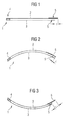
- FIG. 1 shows a flexible display unit 1 which at least a first flexible surface element 2 and a second flexible surface element 3, wherein the first 2 and the second flexible surface element 3 above the other or are arranged parallel to each other.
- the first flexible surface element 2 and the second flexible sheet 3 are attached to one another at an intended attachment point 4. This means that at this attachment point 4 itself the first 2 and the second flexible surface element to each other move or move.
- first flexible surface element 2 or second flexible surface element 3 On at least the first flexible surface element 2 or second flexible surface element 3 is a conductive Structure 5, about which a shift from the first flexible surface element 2 to the second flexible surface element 3 can be measured.
- the conductive structures thus form part of a Measuring device dar.
- the flexible display unit 1 is in unbent State or initial state shown.
- the conductive Structures 5 each in each edge region of the first flexible sheet 2 and the second flexible Surface element 3 is arranged. In other words, located the conductive structures 5 at the with respect to the attachment point opposite ends of the first 2 and the second flexible surface element.
- Both surface elements can - as shown in Fig. 1 - different be great.
- This has the advantage of being conductive Structures directly on the edge of the flexible surface elements can be applied.
- unbent Condition then soften the edges or ends of the conductive Structures about a distance 1 from each other. The length this route and thus the location of the conductive structure 5 on the first flexible sheet 2 to the conductive Structure 5 on the second flexible sheet 3 changes depending on the bending of the flexible Display unit 1, which is accessible to a measurement. For example This results in a capacitive measuring device a capacity change.
- the flexible display unit is in a bent State to see. Because first and second flexible Surface element at the attachment point 4 to each other are fixed, move the first flexible surface element 2 and the second flexible surface element 3 and thus the respective conductive structures 5 relative to each other. In order to for example, reduces the distance of the edges of the two conductive structures 5 to each other, which in the drawing is characterized by 1-.
- FIG. 3 shows a bending of the flexible display unit 1 to see in the direction opposite to Figure 2 direction.
- the conductive structure 5 moves in the second flexible surface element 3 relative to the conductive structure. 5 on the first flexible surface element 2 so that the distance the outer margins is enlarged, which in the drawing characterized by the size 1+.
- first flexible surface element 2 and / or the second flexible surface element 3 may be, for example Plastic films, such as films of polyamide, polypropylene or PTFE (Teflon) or similar materials.
- the Attachment of the two flexible surface elements to each other can be done by welding or gluing.
- the choice of suitable attachment method depends on the materials used from and on the geometry of the attachment point. For example, bonding can be beneficial for large areas Attachment points.
- one of the two flexible surface elements a have integrated display, which for displaying Screen content is used.
- a measuring device can, for example, inductive or based on capacitive measurement methods.
- the advantage of these measuring methods is that they are carried out without contact can.
- it may be at or the conductive structure (s) 5 to conductive layers of various Geometry acting on the respective flexible Surface element are applied.
- the conductive Structure on the first flexible surface element 2 of a Head exist, which is traversed by electricity and on the second flexible surface element 3, for example a coil or a current through which also flows Ladder.
- a conductive material for example, copper to get voted.
- the area on which the conductive structure 5 is applied respectively will be chosen so that in this area a deformation of the flexible display unit clearly noticeable power.
- the conductive structure 5 each with the flexible surface element complete that is in the area of the edge of the flexible Surface element to be applied. That has shown in the Geometry also has the advantage that this area as possible far from the attachment point 4, thereby the relative displacement of first and second flexible Surface element is clear.
- display unit 1 may also be sufficient the conductive structure or the conductive structures 5 closer to arrange at the attachment point 4. This can too For example, when required by the attachment point removed area, for example, by other modules is occupied.
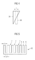
- an advantageous embodiment of the conductive is now Structures 5 on the respective flexible surface elements to see.
- the conductive structure 5A moves on the first flexible surface element relative to a conductive structure 5B on the second flexible sheet 3, it changes through the conductive structures 5A and 5B, capacitance by changing the area the capacitor plates.
- the size change of the capacity can also be determined.
- FIG. 5 another embodiment of a conductive Structure to see, for example, even with a rectangular Structure like the conductive structure 5B on the second surface element 3 in Figure 4 or the conductive Structure 5A combined on the first surface element 2 in Figure 4 can be.
- the conductive structure 5C becomes formed like a comb.
- comb spikes 6, for example a width d, while spaces 7 a width D have.
- the conductive structure 5C for example, on the second flexible surface element 3 applied, it results during (the expiration) a bending a sudden change in capacity with the bend, depending on whether a ridge 6 or a Interspace 7 in the overlap region of the two conductive Structures out or in. So it can signal pulses be recorded, here the number of registered Signal pulses starting from the initial state a measure of the Bending is.
- the widths d of the comb spikes 6 and the width D of the spaces 7 may vary depending on the overall geometry of the flexible display unit 1 can be selected. In particular it also provided, comb spikes 6 or spaces 7 different broad shape. So can at a larger relative Displacement in case of severe bending accounted for that is, for example, that larger bends not distorted, but still recorded linear. This is advantageous in the generation of control signals.
- control signals are dependent on the size of the Capacitance or inductance or even a change generated the respective size. Like from an electrical Size or the change of an electrical variable, a control signal is derived, is known in the art, which is why will not be discussed further here.
- a conductive Structure 5, 5A, 5B, 5C also be designed so that They not only like the conductive structure 5A or the conductive Structure 5C has a change in one dimension, for example, the comb spikes or the tapered bar, but that the conductive structure is also in one second dimension changes.
Landscapes
- Engineering & Computer Science (AREA)
- General Engineering & Computer Science (AREA)
- Theoretical Computer Science (AREA)
- Human Computer Interaction (AREA)
- Physics & Mathematics (AREA)
- General Physics & Mathematics (AREA)
- Measurement Of Length, Angles, Or The Like Using Electric Or Magnetic Means (AREA)
- Devices For Indicating Variable Information By Combining Individual Elements (AREA)
Abstract
Description
- Figur 1
- Eine flexible Anzeigeeinheit mit flexiblen Flächenelementen.;
- Figur 2
- eine Verbiegung der flexiblen Anzeigeeinheit aus Figur 1;
- Figur 3
- eine andere Verbiegung der flexiblen Anzeigeeinheit aus Figur 1;
- Figur 4
- eine Ausgestaltung einer leitfähigen Struktur auf den flexiblen Flächenelementen; und
- Figur 5
- eine andere Ausgestaltung einer leitfähigen Struktur auf einer flexiblen Flächenelement.
- 1
- flexible Anzeigeeinheit
- 2
- erstes flexibles Flächenelement
- 3
- zweites flexibles Flächenelement
- 4
- Befestigungsstelle
- 5
- leitfähige Struktur
- 5A
- leitfähige Struktur in Form eines sich verjüngenden Balkens
- 5B
- leitfähige Struktur in Form eines Rechtecks
- 5C
- leitfähige Struktur in Form eines Kamms
- 6
- Kammzacken
- 7
- Zwischenräume
Claims (11)
- Flexible Anzeigeeinheit (1) zum Darstellen von Bildinhalten und Eingeben von Steuerinformation durch Verbiegen der Anzeigeeinheit, welche folgende Komponenten aufweist:a) ein erstes flexibles Flächenelement (2) und ein zweites flexibles Flächenelement (3), die an einer Befestigungsstelle (4) aneinander befestigt sind;b) ein Messelement zum Erfassen einer Verschiebung der flexiblen Flächenelemente zueinander, welche aufgrund einer Verbiegung von dem ersten flexiblen Flächenelement (2) und zweitem flexiblen Flächenelement(3) zwischen der Befestigungsstelle (4) und dem Messelement auftritt, und zum Ausgeben eines der Verschiebung entsprechenden elektrischen Signals;c) Umwandlungseinheit zum Umwandeln des elektrischen Signals in Steuerinformation.
- Anzeigeeinheit (1) nach Anspruch 1, bei der es sich bei zumindest einem flexiblem Flächenelement (2,3) um eine Folie oder eine flexible Leiterplatte handelt.
- Anzeigeeinheit (1) nach Anspruch 1 oder 2, bei der auf dem ersten (2) oder/und auf dem zweiten Flächenelement (3) eine leitfähige Struktur (5) aufgebracht ist.
- Anzeigeeinheit (1) nach einem der vorhergehenden Ansprüche, bei der das Messelement jeweils eine leitfähige Struktur auf dem ersten (2) und dem zweiten flexiblen Flächenelement (3) umfasst.
- Anzeigeeinheit (1) nach Anspruch 3 oder 4, bei der eine leitfähige Struktur (5) durch einen sich in der Ebene der Struktur nach einer Richtung hin verjüngenden Balken gebildet wird.
- Anzeigeeinheit (1) nach einem der Ansprüche 3 bis 5, bei der eine leitfähige Struktur (5) eine kammartige Form aufweist.
- Anzeigeeinheit (1) nach einem der Ansprüche 1 bis 6, bei der es sich bei dem Messelement um eine kapazitive oder induktive Messvorrichtung handelt.
- Anzeigeeinheit (1) nach einem der Ansprüche 1 bis 7 bei der die flexiblen Flächenelemente (2,3) durch eine Schweißstelle oder eine Verklebung zwischen den flexiblen Flächenelementen aneinander befestigt werden.
- Anzeigeeinheit (1) nach einem der vorhergehenden Ansprüche, welches ferner ein Display zum Darstellen der Bildinhalte aufweist, welches in einem der flexiblen Flächenelemente (2,3) integriert ist.
- Elektrisches Gerät mit einer Anzeigeeinheit (1) nach einem der vorhergehenden Ansprüche.
- Elektrisches Gerät nach Anspruch 10, welches als tragbares Kommunikationsgerät, insbesondere als Mobilfunkgerät, ausgebildet ist.
Applications Claiming Priority (2)
| Application Number | Priority Date | Filing Date | Title |
|---|---|---|---|
| DE10355415A DE10355415A1 (de) | 2003-11-27 | 2003-11-27 | Flexible Anzeigeeinheit und elektrisches Gerät mit einer flexiblen Anzeigeeinheit |
| DE10355415 | 2003-11-27 |
Publications (2)
| Publication Number | Publication Date |
|---|---|
| EP1548550A2 true EP1548550A2 (de) | 2005-06-29 |
| EP1548550A3 EP1548550A3 (de) | 2016-01-06 |
Family
ID=34530317
Family Applications (1)
| Application Number | Title | Priority Date | Filing Date |
|---|---|---|---|
| EP04105643.3A Withdrawn EP1548550A3 (de) | 2003-11-27 | 2004-11-09 | Flexible Anzeigeeinheit für Benutzereingabe und Gerät mit einer solchen Anzeigeeinheit |
Country Status (2)
| Country | Link |
|---|---|
| EP (1) | EP1548550A3 (de) |
| DE (1) | DE10355415A1 (de) |
Cited By (2)
| Publication number | Priority date | Publication date | Assignee | Title |
|---|---|---|---|---|
| US9766762B2 (en) | 2013-11-14 | 2017-09-19 | Nokia Technologies Oy | Flexible device deformation measurement |
| DE102020212095A1 (de) | 2020-09-25 | 2022-03-31 | Robert Bosch Gesellschaft mit beschränkter Haftung | Anzeigevorrichtung für einen Innenraum eines Fahrzeugs und Fahrzeug mit Anzeigevorrichtung |
Family Cites Families (4)
| Publication number | Priority date | Publication date | Assignee | Title |
|---|---|---|---|---|
| US5610528A (en) * | 1995-06-28 | 1997-03-11 | International Business Machines Corporation | Capacitive bend sensor |
| US6297838B1 (en) * | 1997-08-29 | 2001-10-02 | Xerox Corporation | Spinning as a morpheme for a physical manipulatory grammar |
| US6535200B2 (en) * | 1999-01-25 | 2003-03-18 | Harald Philipp | Capacitive position sensor |
| DE10206185A1 (de) * | 2002-02-14 | 2003-05-15 | Siemens Ag | Anzeigeeinheit und Kommunikationsgerät mit einer Anzeigeeinheit |
-
2003
- 2003-11-27 DE DE10355415A patent/DE10355415A1/de not_active Withdrawn
-
2004
- 2004-11-09 EP EP04105643.3A patent/EP1548550A3/de not_active Withdrawn
Non-Patent Citations (1)
| Title |
|---|
| None * |
Cited By (2)
| Publication number | Priority date | Publication date | Assignee | Title |
|---|---|---|---|---|
| US9766762B2 (en) | 2013-11-14 | 2017-09-19 | Nokia Technologies Oy | Flexible device deformation measurement |
| DE102020212095A1 (de) | 2020-09-25 | 2022-03-31 | Robert Bosch Gesellschaft mit beschränkter Haftung | Anzeigevorrichtung für einen Innenraum eines Fahrzeugs und Fahrzeug mit Anzeigevorrichtung |
Also Published As
| Publication number | Publication date |
|---|---|
| DE10355415A1 (de) | 2005-06-30 |
| EP1548550A3 (de) | 2016-01-06 |
Similar Documents
| Publication | Publication Date | Title |
|---|---|---|
| DE60007631T2 (de) | Tragbares oder taschenformat elektronisches gerät und tragbares eingabegerät | |
| DE69731299T2 (de) | Berührungsbildschirm | |
| DE102010007486A1 (de) | Bedienvorrichtung | |
| DE102009037211A1 (de) | Elektronische Vorrichtung | |
| EP2737387B1 (de) | Bedienvorrichtung | |
| DE102006060068A1 (de) | Zeigegerät, das für kleine Handgeräte angepasst ist | |
| DE102007001086A1 (de) | Einrichtung zur Veränderung von Kapazität | |
| DE102017105954A1 (de) | Berührungsanzeigefeld und Berührungsanzeigevorrichtung | |
| EP0955691A2 (de) | Kontaktierungsvorrichtung | |
| DE102018126944A1 (de) | Bildschirm-Tastfeld und tragbare Vorrichtung | |
| WO2004034241A2 (de) | Schnell-eingabevorrichtung | |
| DE102010052991A1 (de) | Portabler Datenträger | |
| WO2007014780A1 (de) | Bedienelement für ein kraftfahrzeug | |
| DE102016108899A1 (de) | Kombiniertes Ein- und Ausgabegerät und Verfahren zur Bedienung eines Ein- und Ausgabegerätes | |
| EP1548550A2 (de) | Flexible Anzeigeeinheit für Benutzereingabe und Gerät mit einer solchen Anzeigeeinheit | |
| DE102013000193A1 (de) | Bildschirm-Tastfeld bzw. Touch-Panel | |
| DE112016003061B4 (de) | Eingabevorrichtung | |
| DE10143275A1 (de) | Eingabeeinrichtung eines elektronischen Gerätes | |
| DE4222940A1 (de) | Tastatur mit Maus-Eingabefeld | |
| DE10311294A1 (de) | Stufenlos betätigbare Tasten einer Tastatur mit integriertem Signalerfassungselement und Verfahren zur Signalverarbeitung | |
| DE102006020568A1 (de) | Anzeigevorrichtung zur taktil erfassbaren Darstellung von Anzeigeelementen sowie Anzeigesystem mit einer solchen Anzeigevorrichtung | |
| DE102024119753B3 (de) | Maus | |
| AT517172A1 (de) | Eingabeelement für elektronische Geräte | |
| DE102012218813A1 (de) | Elektrisches Gerät, insbesondere Telekommunikationsgerät, mit einer Projektionseinrichtung und Verfahren zum Betrieb eines elektrischen Geräts | |
| DE10223976A1 (de) | Anzeigeeinrichtung mit Eingabemöglichkeit |
Legal Events
| Date | Code | Title | Description |
|---|---|---|---|
| PUAI | Public reference made under article 153(3) epc to a published international application that has entered the european phase |
Free format text: ORIGINAL CODE: 0009012 |
|
| AK | Designated contracting states |
Kind code of ref document: A2 Designated state(s): AT BE BG CH CY CZ DE DK EE ES FI FR GB GR HU IE IS IT LI LU MC NL PL PT RO SE SI SK TR |
|
| AX | Request for extension of the european patent |
Extension state: AL HR LT LV MK YU |
|
| RAP1 | Party data changed (applicant data changed or rights of an application transferred) |
Owner name: BENQ MOBILE GMBH & CO. OHG |
|
| 19U | Interruption of proceedings before grant |
Effective date: 20070101 |
|
| 19W | Proceedings resumed before grant after interruption of proceedings |
Effective date: 20070702 |
|
| 19W | Proceedings resumed before grant after interruption of proceedings |
Effective date: 20091001 |
|
| RAP1 | Party data changed (applicant data changed or rights of an application transferred) |
Owner name: PALM, INC. |
|
| RAP1 | Party data changed (applicant data changed or rights of an application transferred) |
Owner name: HEWLETT-PACKARD DEVELOPMENT COMPANY, L.P. |
|
| RAP1 | Party data changed (applicant data changed or rights of an application transferred) |
Owner name: QUALCOMM INCORPORATED |
|
| PUAL | Search report despatched |
Free format text: ORIGINAL CODE: 0009013 |
|
| AK | Designated contracting states |
Kind code of ref document: A3 Designated state(s): AT BE BG CH CY CZ DE DK EE ES FI FR GB GR HU IE IS IT LI LU MC NL PL PT RO SE SI SK TR |
|
| AX | Request for extension of the european patent |
Extension state: AL HR LT LV MK YU |
|
| RIC1 | Information provided on ipc code assigned before grant |
Ipc: G06F 3/02 20060101AFI20151203BHEP Ipc: G02F 1/1333 20060101ALI20151203BHEP Ipc: G01L 1/14 20060101ALI20151203BHEP Ipc: G01B 7/16 20060101ALI20151203BHEP |
|
| 17P | Request for examination filed |
Effective date: 20160706 |
|
| RBV | Designated contracting states (corrected) |
Designated state(s): AT BE BG CH CY CZ DE DK EE ES FI FR GB GR HU IE IS IT LI LU MC NL PL PT RO SE SI SK TR |
|
| AKX | Designation fees paid |
Designated state(s): AT BE BG CH CY CZ DE DK EE ES FI FR GB GR HU IE IS IT LI LU MC NL PL PT RO SE SI SK TR |
|
| AXX | Extension fees paid |
Extension state: MK Extension state: HR Extension state: AL Extension state: YU Extension state: LV Extension state: LT |
|
| STAA | Information on the status of an ep patent application or granted ep patent |
Free format text: STATUS: EXAMINATION IS IN PROGRESS |
|
| 17Q | First examination report despatched |
Effective date: 20170330 |
|
| GRAP | Despatch of communication of intention to grant a patent |
Free format text: ORIGINAL CODE: EPIDOSNIGR1 |
|
| STAA | Information on the status of an ep patent application or granted ep patent |
Free format text: STATUS: GRANT OF PATENT IS INTENDED |
|
| INTG | Intention to grant announced |
Effective date: 20180504 |
|
| STAA | Information on the status of an ep patent application or granted ep patent |
Free format text: STATUS: THE APPLICATION IS DEEMED TO BE WITHDRAWN |
|
| RIC1 | Information provided on ipc code assigned before grant |
Ipc: G01B 7/16 20060101ALI20151203BHEP Ipc: G06F 3/02 20060101AFI20151203BHEP Ipc: G01L 1/14 20060101ALI20151203BHEP Ipc: G02F 1/1333 20060101ALI20151203BHEP |
|
| 18D | Application deemed to be withdrawn |
Effective date: 20180915 |