EP1548550A2 - Flexible display for user input and device with such flexible display - Google Patents
Flexible display for user input and device with such flexible display Download PDFInfo
- Publication number
- EP1548550A2 EP1548550A2 EP04105643A EP04105643A EP1548550A2 EP 1548550 A2 EP1548550 A2 EP 1548550A2 EP 04105643 A EP04105643 A EP 04105643A EP 04105643 A EP04105643 A EP 04105643A EP 1548550 A2 EP1548550 A2 EP 1548550A2
- Authority
- EP
- European Patent Office
- Prior art keywords
- display unit
- flexible
- flexible surface
- surface element
- conductive structure
- Prior art date
- Legal status (The legal status is an assumption and is not a legal conclusion. Google has not performed a legal analysis and makes no representation as to the accuracy of the status listed.)
- Withdrawn
Links
Images
Classifications
-
- G—PHYSICS
- G06—COMPUTING OR CALCULATING; COUNTING
- G06F—ELECTRIC DIGITAL DATA PROCESSING
- G06F3/00—Input arrangements for transferring data to be processed into a form capable of being handled by the computer; Output arrangements for transferring data from processing unit to output unit, e.g. interface arrangements
- G06F3/01—Input arrangements or combined input and output arrangements for interaction between user and computer
- G06F3/03—Arrangements for converting the position or the displacement of a member into a coded form
- G06F3/033—Pointing devices displaced or positioned by the user, e.g. mice, trackballs, pens or joysticks; Accessories therefor
- G06F3/0338—Pointing devices displaced or positioned by the user, e.g. mice, trackballs, pens or joysticks; Accessories therefor with detection of limited linear or angular displacement of an operating part of the device from a neutral position, e.g. isotonic or isometric joysticks
-
- G—PHYSICS
- G06—COMPUTING OR CALCULATING; COUNTING
- G06F—ELECTRIC DIGITAL DATA PROCESSING
- G06F3/00—Input arrangements for transferring data to be processed into a form capable of being handled by the computer; Output arrangements for transferring data from processing unit to output unit, e.g. interface arrangements
- G06F3/01—Input arrangements or combined input and output arrangements for interaction between user and computer
- G06F3/017—Gesture based interaction, e.g. based on a set of recognized hand gestures
-
- G—PHYSICS
- G06—COMPUTING OR CALCULATING; COUNTING
- G06F—ELECTRIC DIGITAL DATA PROCESSING
- G06F3/00—Input arrangements for transferring data to be processed into a form capable of being handled by the computer; Output arrangements for transferring data from processing unit to output unit, e.g. interface arrangements
- G06F3/01—Input arrangements or combined input and output arrangements for interaction between user and computer
- G06F3/048—Interaction techniques based on graphical user interfaces [GUI]
- G06F3/0487—Interaction techniques based on graphical user interfaces [GUI] using specific features provided by the input device, e.g. functions controlled by the rotation of a mouse with dual sensing arrangements, or of the nature of the input device, e.g. tap gestures based on pressure sensed by a digitiser
Definitions
- the invention relates to a flexible display unit and a electrical device with a flexible display unit.
- Input units such as the keyboard
- touch screens i. a touch-sensitive Umbrella
- Touch screens are typed by having a capacity changed in a certain area of the touch screen , whereby a control signal for performing a function can be generated.
- a flexible display unit In a flexible display unit is at least a first flexible surface element and a second flexible surface element intended. These are one above the other or parallel to each other arranged and at a predetermined attachment point attached to each other. Will now be the flexible display unit bent, so move and move first and second flexible surface element relative to each other. These Relative displacement to each other can be via a measuring element be recorded. The displacement detected by the measuring element is converted into an electrical signal, which is called Control information is used.
- the flexible surface elements may be, for example to act a foil or flexible circuit board. This has the advantage that, for example, films also multiple functionality can perceive, such as a use as a display.
- a flexible circuit board can also be used for electronic circuitry can be used.
- the measuring element may have a conductive structure, the on the first or on the second surface element or both is applied.
- conductive structures can be realize capacitive or inductive measuring elements.
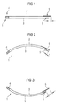
- FIG. 1 shows a flexible display unit 1 which at least a first flexible surface element 2 and a second flexible surface element 3, wherein the first 2 and the second flexible surface element 3 above the other or are arranged parallel to each other.
- the first flexible surface element 2 and the second flexible sheet 3 are attached to one another at an intended attachment point 4. This means that at this attachment point 4 itself the first 2 and the second flexible surface element to each other move or move.
- first flexible surface element 2 or second flexible surface element 3 On at least the first flexible surface element 2 or second flexible surface element 3 is a conductive Structure 5, about which a shift from the first flexible surface element 2 to the second flexible surface element 3 can be measured.
- the conductive structures thus form part of a Measuring device dar.
- the flexible display unit 1 is in unbent State or initial state shown.
- the conductive Structures 5 each in each edge region of the first flexible sheet 2 and the second flexible Surface element 3 is arranged. In other words, located the conductive structures 5 at the with respect to the attachment point opposite ends of the first 2 and the second flexible surface element.
- Both surface elements can - as shown in Fig. 1 - different be great.
- This has the advantage of being conductive Structures directly on the edge of the flexible surface elements can be applied.
- unbent Condition then soften the edges or ends of the conductive Structures about a distance 1 from each other. The length this route and thus the location of the conductive structure 5 on the first flexible sheet 2 to the conductive Structure 5 on the second flexible sheet 3 changes depending on the bending of the flexible Display unit 1, which is accessible to a measurement. For example This results in a capacitive measuring device a capacity change.
- the flexible display unit is in a bent State to see. Because first and second flexible Surface element at the attachment point 4 to each other are fixed, move the first flexible surface element 2 and the second flexible surface element 3 and thus the respective conductive structures 5 relative to each other. In order to for example, reduces the distance of the edges of the two conductive structures 5 to each other, which in the drawing is characterized by 1-.
- FIG. 3 shows a bending of the flexible display unit 1 to see in the direction opposite to Figure 2 direction.
- the conductive structure 5 moves in the second flexible surface element 3 relative to the conductive structure. 5 on the first flexible surface element 2 so that the distance the outer margins is enlarged, which in the drawing characterized by the size 1+.
- first flexible surface element 2 and / or the second flexible surface element 3 may be, for example Plastic films, such as films of polyamide, polypropylene or PTFE (Teflon) or similar materials.
- the Attachment of the two flexible surface elements to each other can be done by welding or gluing.
- the choice of suitable attachment method depends on the materials used from and on the geometry of the attachment point. For example, bonding can be beneficial for large areas Attachment points.
- one of the two flexible surface elements a have integrated display, which for displaying Screen content is used.
- a measuring device can, for example, inductive or based on capacitive measurement methods.
- the advantage of these measuring methods is that they are carried out without contact can.
- it may be at or the conductive structure (s) 5 to conductive layers of various Geometry acting on the respective flexible Surface element are applied.
- the conductive Structure on the first flexible surface element 2 of a Head exist, which is traversed by electricity and on the second flexible surface element 3, for example a coil or a current through which also flows Ladder.
- a conductive material for example, copper to get voted.
- the area on which the conductive structure 5 is applied respectively will be chosen so that in this area a deformation of the flexible display unit clearly noticeable power.
- the conductive structure 5 each with the flexible surface element complete that is in the area of the edge of the flexible Surface element to be applied. That has shown in the Geometry also has the advantage that this area as possible far from the attachment point 4, thereby the relative displacement of first and second flexible Surface element is clear.
- display unit 1 may also be sufficient the conductive structure or the conductive structures 5 closer to arrange at the attachment point 4. This can too For example, when required by the attachment point removed area, for example, by other modules is occupied.
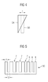
- an advantageous embodiment of the conductive is now Structures 5 on the respective flexible surface elements to see.
- the conductive structure 5A moves on the first flexible surface element relative to a conductive structure 5B on the second flexible sheet 3, it changes through the conductive structures 5A and 5B, capacitance by changing the area the capacitor plates.
- the size change of the capacity can also be determined.
- FIG. 5 another embodiment of a conductive Structure to see, for example, even with a rectangular Structure like the conductive structure 5B on the second surface element 3 in Figure 4 or the conductive Structure 5A combined on the first surface element 2 in Figure 4 can be.
- the conductive structure 5C becomes formed like a comb.
- comb spikes 6, for example a width d, while spaces 7 a width D have.
- the conductive structure 5C for example, on the second flexible surface element 3 applied, it results during (the expiration) a bending a sudden change in capacity with the bend, depending on whether a ridge 6 or a Interspace 7 in the overlap region of the two conductive Structures out or in. So it can signal pulses be recorded, here the number of registered Signal pulses starting from the initial state a measure of the Bending is.
- the widths d of the comb spikes 6 and the width D of the spaces 7 may vary depending on the overall geometry of the flexible display unit 1 can be selected. In particular it also provided, comb spikes 6 or spaces 7 different broad shape. So can at a larger relative Displacement in case of severe bending accounted for that is, for example, that larger bends not distorted, but still recorded linear. This is advantageous in the generation of control signals.
- control signals are dependent on the size of the Capacitance or inductance or even a change generated the respective size. Like from an electrical Size or the change of an electrical variable, a control signal is derived, is known in the art, which is why will not be discussed further here.
- a conductive Structure 5, 5A, 5B, 5C also be designed so that They not only like the conductive structure 5A or the conductive Structure 5C has a change in one dimension, for example, the comb spikes or the tapered bar, but that the conductive structure is also in one second dimension changes.
Landscapes
- Engineering & Computer Science (AREA)
- General Engineering & Computer Science (AREA)
- Theoretical Computer Science (AREA)
- Human Computer Interaction (AREA)
- Physics & Mathematics (AREA)
- General Physics & Mathematics (AREA)
- Measurement Of Length, Angles, Or The Like Using Electric Or Magnetic Means (AREA)
- Devices For Indicating Variable Information By Combining Individual Elements (AREA)
Abstract
Description
Die Erfindung betrifft eine flexible Anzeigeeinheit und ein elektrisches Gerät mit einer flexiblen Anzeigeeinheit.The invention relates to a flexible display unit and a electrical device with a flexible display unit.
Kommunikationsgeräte, wie beispielsweise Mobiltelefone oder tragbare Computer, erfuhren in den letzten Jahren eine fortschreitende Miniaturisierung, um den Gebrauch unterwegs zu erleichtern. Diese fortschreitende Miniaturisierung bringt neben der besseren Tragbarkeit anderseits erhebliche Probleme hinsichtlich des Komforts der Bedienung mit sich. Auf Grund der im Vergleich zu früheren Kommunikationsgeräten kleineren Gehäuseoberfläche ist es nicht mehr möglich, diese mit einer dem Funktionsumfang der Geräte entsprechenden Anzahl von Tasten zu versehen.Communication devices, such as mobile phones or portable computers, have experienced a progressive in recent years Miniaturization to keep you on the move facilitate. This progressive miniaturization brings in addition to better portability on the other hand, significant problems in terms of comfort of service. On reason the smaller compared to previous communication devices Housing surface, it is no longer possible, this with a the number of keys corresponding to the functional scope of the devices to provide.
Da auch die zunehmende Mehrfachbelegung von Tasten dem Bedienkomfort nicht zuträglich ist, werden zunehmend auch die Eingabeeinheiten, beispielsweise die Tastatur, in andere Geräteteile integriert. Insbesondere die Verbindung zwischen einer Anzeigeeinheit bzw. Display und einer Eingabeeinheit, beispielsweise als sogenannte "Touch Screens", d.h. eines berührungssensitiven Schirms, wird vielfach verwendet.As well as the increasing multiple use of keys the ease of use is not conducive, are increasingly the Input units, such as the keyboard, in other parts of the device integrated. In particular, the connection between a display unit and an input unit, for example, as so-called "touch screens", i. a touch-sensitive Umbrella, is widely used.
Beispielsweise bei den auf Kapazitätsänderungen basierenden Touch Screens erfolgt eine Eingabe dadurch, dass eine Kapazität in einem gewissen Bereich des Touch Screens verändert wird, wodurch ein Steuersignal zum Durchführen einer Funktion generierbar ist.For example, based on capacity changes Touch screens are typed by having a capacity changed in a certain area of the touch screen , whereby a control signal for performing a function can be generated.
Da eine Eingabe über einen Druck mit der Fingerkuppe relativ viel Platz erfordert, wird zumeist ein zusätzlicher Stift erforderlich, mit welchem die Auswahl auf dem Touch Screen getroffen wird. Dieser zusätzliche Stift verschlechtert wiederum die Handhabbarkeit des Kommunikationsgerätes, da nun entweder beide Hände oder eine Auflagefläche nötig sind, und eben auch der zusätzliche Stift mitgeführt werden muss.As an input about a pressure with the fingertip relative requires a lot of space, an additional pen is usually required, which made the selection on the touch screen becomes. This additional pen deteriorates again the handling of the communication device, because now either both hands or a support surface are needed, and just the additional pin must be carried.
Ausgehend von diesem Stand der Technik ist es Aufgabe der vorliegenden Erfindung, eine Möglichkeit zu schaffen, mittels der sich auch Informationen einfach und ohne zusätzliche Hilfsmittel eingeben lassen.Based on this prior art, it is the task of present invention to provide a way by means of The information is also simple and without additional Enter aid.
Diese Aufgabe wird durch die unabhängigen Ansprüche gelöst. Vorteilhafte Weiterbildungen sind Gegenstand der abhängigen Ansprüche.This object is solved by the independent claims. Advantageous developments are the subject of the dependent Claims.
Bei einer flexiblen Anzeigeeinheit ist zumindest ein erstes flexibles Flächenelement und ein zweites flexibles Flächenelement vorgesehen. Diese sind übereinander bzw. parallel zueinander angeordnet und an einer vorgegebenen Befestigungsstelle aneinander befestigt. Wird nun die flexible Anzeigeeinheit verbogen, so bewegen bzw. verschieben sich erstes und zweites flexibles Flächenelement relativ zueinander. Diese relative Verschiebung zueinander kann über ein Messelement erfasst werden. Die vom Messelement erfasste Verschiebung wird in ein elektrisches Signal umgewandelt, welches als Steuerinformation verwendet wird.In a flexible display unit is at least a first flexible surface element and a second flexible surface element intended. These are one above the other or parallel to each other arranged and at a predetermined attachment point attached to each other. Will now be the flexible display unit bent, so move and move first and second flexible surface element relative to each other. These Relative displacement to each other can be via a measuring element be recorded. The displacement detected by the measuring element is converted into an electrical signal, which is called Control information is used.
Mit einer derartigen flexiblen Anzeigeeinheit können ein oder mehrere Eingabefunktionen oder Werte vom Benutzer beeinflusst werden. Dadurch wird ein Eingabeelement realisiert, welches zusätzlich zu bisherigen, wie beispielsweise Tasten, Kippschalter, Steuerknüppel, Maus usw., oder allein verwendet werden kann.With such a flexible display unit one or multiple input functions or values influenced by the user become. This realizes an input element which in addition to previous ones, such as buttons, Toggle switch, joystick, mouse, etc., or used alone can be.
Bei der alleinigen Verwendung der flexiblen Anzeigeeinheit als Eingabeelement oder z.B. einer durch die zusätzlichen Eingabemöglichkeiten bei der flexiblen Anzeigeeinheit möglichen Verringerung der Tastenanzahl kann somit ein elektrisches Gerät, in das diese Anzeigeeinheit eingebaut wird, miniaturisiert werden.When using the flexible display unit alone as an input element or e.g. one by the extra Possible entries in the flexible display unit possible Reducing the number of keys can thus be an electrical one Device in which this display unit is installed, miniaturized become.
Alternativ können so bei gleichbleibender Größe des elektrischen Geräts erweiterte Eingabemöglichkeiten vorgesehen werden.Alternatively, so with constant size of the electric Device extended input options are provided.
Bei den flexiblen Flächenelementen kann es sich beispielsweise um eine Folie oder flexible Leiterplatte handeln. Dies hat den Vorteil, dass beispielsweise Folien auch Mehrfachfunktionalität wahrnehmen können, wie beispielsweise eine Verwendung als Display. Eine flexible Leiterplatte kann zugleich zur elektronischen Beschaltung verwendet werden.The flexible surface elements may be, for example to act a foil or flexible circuit board. this has the advantage that, for example, films also multiple functionality can perceive, such as a use as a display. A flexible circuit board can also be used for electronic circuitry can be used.
Das Messelement kann eine leitfähige Struktur aufweisen, die auf dem ersten oder auf dem zweiten Flächenelement oder beiden aufgebracht ist. Mit leitfähigen Strukturen lassen sich kapazitive oder induktive Messelemente realisieren.The measuring element may have a conductive structure, the on the first or on the second surface element or both is applied. With conductive structures can be realize capacitive or inductive measuring elements.
Die Erfindung wird im Folgenden anhand ausgewählter Beispiele unter Zuhilfenahme von Figuren näher erläutert.The invention will be described below with reference to selected examples explained in more detail with the aid of figures.
Es zeigen:
- Figur 1
- Eine flexible Anzeigeeinheit mit flexiblen Flächenelementen.;
Figur 2- eine Verbiegung der flexiblen Anzeigeeinheit aus Figur 1;
Figur 3- eine andere Verbiegung der flexiblen Anzeigeeinheit aus Figur 1;
Figur 4- eine Ausgestaltung einer leitfähigen Struktur auf den flexiblen Flächenelementen; und
Figur 5- eine andere Ausgestaltung einer leitfähigen Struktur auf einer flexiblen Flächenelement.
- FIG. 1
- A flexible display unit with flexible surface elements .;
- FIG. 2
- a deflection of the flexible display unit of Figure 1;
- FIG. 3
- another deflection of the flexible display unit of Figure 1;
- FIG. 4
- an embodiment of a conductive structure on the flexible surface elements; and
- FIG. 5
- another embodiment of a conductive structure on a flexible surface element.
In Figur 1 ist eine flexible Anzeigeeinheit 1 zu sehen, welche
zumindest ein erstes flexibles Flächenelement 2 und ein
zweites flexibles Flächenelement 3 aufweist, wobei das erste
2 und das zweite flexible Flächenelement 3 übereinander bzw.
parallel zueinander angeordnet sind. Das erste flexible Flächenelement
2 und das zweite flexible Flächenelement 3 sind
an einer vorgesehenen Befestigungsstelle 4 aneinander befestigt.
Das bedeutet, dass an dieser Befestigungsstelle 4 sich
das erste 2 und das zweite flexible Flächenelement zueinander
verschieben bzw. bewegen.FIG. 1 shows a flexible display unit 1 which
at least a first
Auf zumindest dem ersten flexiblen Flächenelement 2 oder dem
zweiten flexiblen Flächenelement 3 befindet sich eine leitfähige
Struktur 5, über die eine Verschiebung von dem ersten
flexiblen Flächenelement 2 zum zweiten flexiblen Flächenelement
3 gemessen werden kann.On at least the first
Die leitfähigen Strukturen stellen somit einen Teil einer Messeinrichtung dar.The conductive structures thus form part of a Measuring device dar.
In Figur 1 ist die flexible Anzeigeeinheit 1 in unverbogenem
Zustand bzw. Ausgangszustand gezeigt. Hierbei sind die leitfähigen
Strukturen 5 jeweils im jeweiligen Randbereich des
ersten flexiblen Flächenelements 2 und des zweiten flexiblen
Flächenelements 3 angeordnet. Anders ausgedrückt befinden
sich die leitfähigen Strukturen 5 an den in Bezug auf die Befestigungsstelle
entgegengesetzten Enden des ersten 2 und des
zweiten flexiblen Flächenelements.In Figure 1, the flexible display unit 1 is in unbent
State or initial state shown. Here are the
Beide Flächenelemente können - wie in Fig. 1 gezeigt - unterschiedlich
groß sein. Dies hat den Vorteil, dass leitfähige
Strukturen unmittelbar am Rand der flexiblen Flächenelemente
aufgebracht werden können. In dem in Fig.1 gezeigten, unverbogenen
Zustand weichen dann die Ränder bzw. Enden der leitfähigen
Strukturen um eine Strecke 1 voneinander ab. Die Länge
dieser Strecke und damit die Lage der leitfähigen Struktur
5 auf dem ersten flexiblen Flächenelement 2 zur leitfähigen
Struktur 5 auf dem zweiten flexiblen Flächenelement 3 ändert
sich in Abhängigkeit von der Verbiegung der flexiblen
Anzeigeeinheit 1, was einer Messung zugänglich ist. Beispielsweise
ergibt sich dadurch bei einer kapazitiven Messeinrichtung
eine Kapazitätsänderung.Both surface elements can - as shown in Fig. 1 - different
be great. This has the advantage of being conductive
Structures directly on the edge of the flexible surface elements
can be applied. In the one shown in Fig.1, unbent
Condition then soften the edges or ends of the conductive
Structures about a distance 1 from each other. The length
this route and thus the location of the
In Figur 2 ist die flexible Anzeigeeinheit in einem verbogenen
Zustand zu sehen. Dadurch, dass erstes und zweites flexibles
Flächenelement an der Befestigungsstelle 4 aneinander
befestigt sind, bewegen sich das erste flexible Flächenelement
2 und das zweite flexible Flächenelement 3 und damit die
jeweiligen leitfähigen Strukturen 5 relativ zueinander. Damit
verringert sich beispielsweise der Abstand der Ränder der
beiden leitfähigen Strukturen 5 zueinander, was in der Zeichnung
durch 1- gekennzeichnet ist.In Figure 2, the flexible display unit is in a bent
State to see. Because first and second flexible
Surface element at the
In Figur 3 ist eine Verbiegung der flexiblen Anzeigeeinheit 1
in die zu Figur 2 entgegengesetzte Richtung zu sehen. In diesem
Fall bewegt sich die leitfähige Struktur 5 in der zweiten
flexiblen Flächenelement 3 relativ zur leitfähigen Struktur 5
auf der ersten flexiblen Flächenelement 2 so, dass der Abstand
der äußeren Ränder vergrößert ist, was in der Zeichnung
durch die Größe 1+ gekennzeichnet ist.FIG. 3 shows a bending of the flexible display unit 1
to see in the direction opposite to Figure 2 direction. In this
Case, the
Bei dem ersten flexiblen Flächenelement 2 oder/und dem zweiten
flexiblen Flächenelement 3 kann es sich beispielsweise um
Kunststofffolien, wie etwa Folien aus Polyamid, Polyproylen
oder PFTE (Teflon) oder ähnlichen Materialien handeln. Die
Befestigung der beiden flexiblen Flächenelemente aneinander
kann durch Verschweißen oder Verkleben erfolgen. Die Wahl der
geeigneten Befestigungsmethode hängt von den verwendeten Materialien
ab und von der Geometrie der Befestigungsstelle.
Beispielsweise kann ein Verkleben günstig sein für großflächige
Befestigungsstellen. In the first
Weiterhin kann eines der beiden flexiblen Flächenelemente ein integriertes Display aufweisen, welches zum Darstellen von Bildschirminhalten dient.Furthermore, one of the two flexible surface elements a have integrated display, which for displaying Screen content is used.
Eine Messeinrichtung kann beispielsweise auf induktiven oder kapazitiven Messmethoden beruhen. Der Vorteil dieser Messmethoden liegt darin, dass sie berührungslos durchgeführt werden können.A measuring device can, for example, inductive or based on capacitive measurement methods. The advantage of these measuring methods is that they are carried out without contact can.
Für kapazitive Messeinrichtungen kann es sich bei der oder den leitfähigen Struktur(en) 5 um leitfähige Schichten verschiedener Geometrie handeln, welche auf das jeweilige flexible Flächenelement aufgebracht sind.For capacitive measuring devices, it may be at or the conductive structure (s) 5 to conductive layers of various Geometry acting on the respective flexible Surface element are applied.
Bei induktiven Messeinrichtungen zur Messung der Verschiebung
der flexiblen Flächenelement zueinander kann die leitfähige
Struktur auf dem ersten flexiblen Flächenelement 2 aus einem
Leiter bestehen, welcher von Strom durchflossen wird und auf
dem zweiten flexiblen Flächenelement 3 beispielsweise aus
einer Spule oder einem ebenfalls von Strom durchflossenen
Leiter. Als leitfähiges Material kann beispielsweise Kupfer
gewählt werden. Bei der Auswahl des Materials wird auch die
Kompatibilität mit den übrigen Materialien der flexiblen Anzeigeeinheit
1 abgestellt.For inductive measuring devices for measuring the displacement
the flexible surface element to each other, the conductive
Structure on the first
Der Bereich, auf dem die leitfähige Struktur 5 jeweils aufgebracht
wird, wird so gewählt, dass sich in diesem Bereich
eine Verformung der flexiblen Anzeigeeinheit deutlich bemerkbar
macht. Wie in Figur 1 gezeigt, kann beispielsweise die
leitfähige Struktur 5 jeweils mit der flexiblen Flächenelement
abschließen, das heißt im Bereich des Randes der flexiblen
Flächenelement aufgebracht werden. Das hat in der gezeigten
Geometrie auch den Vorteil, dass sich dieser Bereich möglichst
weit von der Befestigungsstelle 4 befindet, wodurch
die relative Verschiebung von erstem und zweitem flexiblen
Flächenelement deutlich ist. Je nach Art und Größe der flexiblen
Anzeigeeinheit 1 kann es jedoch auch ausreichend sein,
die leitfähige Struktur oder die leitfähigen Strukturen 5 näher
an der Befestigungsstelle 4 anzuordnen. Dies kann auch
beispielsweise erforderlich sein, wenn der von der Befestigungsstelle
entfernte Bereich beispielsweise durch andere Module
belegt ist.The area on which the
In Figur 4 ist nun eine vorteilhafte Ausgestaltung der leitfähigen
Strukturen 5 auf den jeweiligen flexiblen Flächenelementen
zu sehen. Beispielsweise ist die leitfähige Struktur
5A auf dem ersten flexiblen Flächenelement in der Ebene des
flexiblen Flächenelements 2 in Form eines sich verjüngenden
Balkens ausgebildet. Bewegt sich die leitfähige Struktur 5A
auf dem ersten flexiblen Flächenelement relativ zu einer
leitfähigen Struktur 5B auf dem zweiten flexiblen Flächenelement
3, so ändert sich die durch die leitfähigen Strukturen
5A und 5B gebildete Kapazität durch eine Änderung der Fläche
der Kondensatorplatten. Je nach Ausgestaltung der Verjüngung
kann auch die Größenänderung der Kapazität bestimmt werden.In Figure 4, an advantageous embodiment of the conductive is now
In Figur 5 ist eine andere Ausgestaltung einer leitfähigen
Struktur zu sehen, die beispielsweise auch mit einer rechteckigen
Struktur wie der leitfähigen Struktur 5B auf dem
zweiten Flächenelement 3 in Figur 4 oder der leitfähigen
Struktur 5A auf dem ersten Flächenelement 2 in Figur 4 kombiniert
werden kann. In Figur 5 wird die leitfähige Struktur 5C
kammartig ausgebildet. Hierbei weisen Kammzacken 6 beispielsweise
eine Breite d auf, während Zwischenräume 7 eine Breite
D aufweisen.In Figure 5, another embodiment of a conductive
Structure to see, for example, even with a rectangular
Structure like the
Ist nun bei einer Abwandlung von Fig. 4 die leitfähige Struktur
5C beispielsweise auf dem zweiten flexiblen Flächenelement
3 aufgebracht, so ergibt sich während (des Ablaufs)
einer Verbiegung eine sprunghafte Änderung der Kapazität mit
der Verbiegung, abhängig davon, ob eine Kammzacke 6 oder ein
Zwischenraum 7 in den Überlappbereich der beiden leitfähigen
Strukturen heraus oder hinein wandert. Es können also Signalpulse
erfasst werden, wobei hier die Anzahl der registrierten
Signalpulse beginnend vom Ausgangszustand ein Maß für die
Verbiegung ist.Is now in a modification of Fig. 4, the
Die Breiten d der Kammzacken 6 sowie die Breite D der Zwischenräume
7 kann in Abhängigkeit von der Gesamtgeometrie der
flexiblen Anzeigeeinheit 1 gewählt werden. Insbesondere ist
es auch vorgesehen, Kammzacken 6 oder Zwischenräume 7 unterschiedlich
breit zu gestalten. So kann bei einer größeren relativen
Verschiebung bei stärkerer Verbiegung Rechnung getragen
werden, das heißt, dass zum Beispiel größere Verbiegungen
nicht verzerrt, sondern noch linear erfasst werden. Dies ist
von Vorteil bei der Generierung von Steuersignalen.The widths d of the comb spikes 6 and the width D of the
Die Steuersignale werden in Abhängigkeit von der Größe der Kapazität oder der Induktivität oder auch von einer Änderung der jeweiligen Größe generiert. Wie aus einer elektrischen Größe bzw. der Änderung einer elektrischen Größe ein Steuersignal abgeleitet wird, ist dem Fachmann bekannt, weshalb hier nicht näher darauf eingegangen wird.The control signals are dependent on the size of the Capacitance or inductance or even a change generated the respective size. Like from an electrical Size or the change of an electrical variable, a control signal is derived, is known in the art, which is why will not be discussed further here.
Um mehrdimensionale Verbiegungen zu erfassen, kann eine leitfähige
Struktur 5, 5A, 5B, 5C auch so ausgestaltet sein, dass
sie nicht nur wie die leitfähige Struktur 5A oder die leitfähige
Struktur 5C eine Änderung in einer Dimension aufweist,
beispielsweise die Kammzacken oder der sich verjüngende Balken,
sondern, dass sich die leitfähige Struktur auch in einer
zweiten Dimension ändert.To capture multidimensional bends, a
Es können weiterhin auch mehr als zwei flexible Flächenelemente vorgesehen sein, beispielsweise um mehr Messgrößen zu generieren, um die Verbiegung sicherer zu erfassen. It can also be more than two flexible surface elements be provided, for example, to more measures too generate to capture the bending more secure.
- 11
- flexible Anzeigeeinheitflexible display unit
- 22
- erstes flexibles Flächenelementfirst flexible surface element
- 33
- zweites flexibles Flächenelementsecond flexible surface element
- 44
- Befestigungsstellefastening point
- 55
- leitfähige Strukturconductive structure
- 5A5A
- leitfähige Struktur in Form eines sich verjüngenden Balkensconductive structure in the form of a tapered beam
- 5B5B
- leitfähige Struktur in Form eines Rechtecksconductive structure in the form of a rectangle
- 5C5C
- leitfähige Struktur in Form eines Kammsconductive structure in the form of a comb
- 66
- Kammzackencomb teeth
- 77
- Zwischenräumeinterspaces
Claims (11)
Applications Claiming Priority (2)
| Application Number | Priority Date | Filing Date | Title |
|---|---|---|---|
| DE10355415A DE10355415A1 (en) | 2003-11-27 | 2003-11-27 | Flexible display unit and electrical device with a flexible display unit |
| DE10355415 | 2003-11-27 |
Publications (2)
| Publication Number | Publication Date |
|---|---|
| EP1548550A2 true EP1548550A2 (en) | 2005-06-29 |
| EP1548550A3 EP1548550A3 (en) | 2016-01-06 |
Family
ID=34530317
Family Applications (1)
| Application Number | Title | Priority Date | Filing Date |
|---|---|---|---|
| EP04105643.3A Withdrawn EP1548550A3 (en) | 2003-11-27 | 2004-11-09 | Flexible display for user input and device with such flexible display |
Country Status (2)
| Country | Link |
|---|---|
| EP (1) | EP1548550A3 (en) |
| DE (1) | DE10355415A1 (en) |
Cited By (2)
| Publication number | Priority date | Publication date | Assignee | Title |
|---|---|---|---|---|
| US9766762B2 (en) | 2013-11-14 | 2017-09-19 | Nokia Technologies Oy | Flexible device deformation measurement |
| DE102020212095A1 (en) | 2020-09-25 | 2022-03-31 | Robert Bosch Gesellschaft mit beschränkter Haftung | Display device for an interior of a vehicle and vehicle with display device |
Family Cites Families (4)
| Publication number | Priority date | Publication date | Assignee | Title |
|---|---|---|---|---|
| US5610528A (en) * | 1995-06-28 | 1997-03-11 | International Business Machines Corporation | Capacitive bend sensor |
| US6297838B1 (en) * | 1997-08-29 | 2001-10-02 | Xerox Corporation | Spinning as a morpheme for a physical manipulatory grammar |
| US6535200B2 (en) * | 1999-01-25 | 2003-03-18 | Harald Philipp | Capacitive position sensor |
| DE10206185A1 (en) * | 2002-02-14 | 2003-05-15 | Siemens Ag | Deformable display for use with miniature communications devices such as mobile phones or PDAs, whereby deformation of the actual display within its frame can be used for command input |
-
2003
- 2003-11-27 DE DE10355415A patent/DE10355415A1/en not_active Withdrawn
-
2004
- 2004-11-09 EP EP04105643.3A patent/EP1548550A3/en not_active Withdrawn
Non-Patent Citations (1)
| Title |
|---|
| None * |
Cited By (2)
| Publication number | Priority date | Publication date | Assignee | Title |
|---|---|---|---|---|
| US9766762B2 (en) | 2013-11-14 | 2017-09-19 | Nokia Technologies Oy | Flexible device deformation measurement |
| DE102020212095A1 (en) | 2020-09-25 | 2022-03-31 | Robert Bosch Gesellschaft mit beschränkter Haftung | Display device for an interior of a vehicle and vehicle with display device |
Also Published As
| Publication number | Publication date |
|---|---|
| EP1548550A3 (en) | 2016-01-06 |
| DE10355415A1 (en) | 2005-06-30 |
Similar Documents
| Publication | Publication Date | Title |
|---|---|---|
| DE60007631T2 (en) | PORTABLE OR POCKET SIZE ELECTRONIC DEVICE AND PORTABLE INPUT DEVICE | |
| DE69731299T2 (en) | TOUCH SCREEN | |
| DE69919494T2 (en) | Device for generating input signals for an electronic device | |
| DE202008001970U1 (en) | Tilting touch control panel | |
| DE102010007486A1 (en) | operating device | |
| DE102009037211A1 (en) | Electronic device | |
| EP2737387B1 (en) | Operating device | |
| WO2009053492A1 (en) | Single-touch or multi-touch capable touch screens or touch pads comprising an array of pressure sensors and production of such sensors | |
| DE102006060068A1 (en) | Pointing device adapted for small handsets | |
| DE202007000157U1 (en) | Device for changing capacity | |
| EP0955691A2 (en) | Contacting device | |
| DE102017105954A1 (en) | Touch display panel and touch display device | |
| DE102018126944A1 (en) | Screen touchpad and portable device | |
| EP2646953B1 (en) | Portable data carrier | |
| DE102005054677A1 (en) | Touch-sensitive control unit with haptic feedback | |
| WO2004034241A2 (en) | Rapid input device | |
| DE112018003675T5 (en) | INFORMATION PROCESSING DEVICE, INFORMATION PROCESSING PROCESS AND PROGRAM | |
| WO2007014780A1 (en) | Control element for a motor vehicle | |
| DE102016108899A1 (en) | Combined input and output device and method for operating an input and output device | |
| EP1548550A2 (en) | Flexible display for user input and device with such flexible display | |
| DE102013007914A1 (en) | Hand held device and unlocking method of this | |
| DE102013000193A1 (en) | Display screen-touchpad and/or touch panel i.e. capacitive touch panel, for use in e.g. mobile communication device, has ground lines arranged on substrate and extending along direction, and circuit units arranged between lines | |
| DE4222940A1 (en) | Dual function keyboard area with numeric keypad simulating mouse field - selectable by program control using x-y input matrix | |
| DE10311294A1 (en) | Integrated system for the identification of keys in a keyboard uses keys with specific resistance values | |
| DE102006020568A1 (en) | Display device for tactile detectable display of display elements and display system with such a display device |
Legal Events
| Date | Code | Title | Description |
|---|---|---|---|
| PUAI | Public reference made under article 153(3) epc to a published international application that has entered the european phase |
Free format text: ORIGINAL CODE: 0009012 |
|
| AK | Designated contracting states |
Kind code of ref document: A2 Designated state(s): AT BE BG CH CY CZ DE DK EE ES FI FR GB GR HU IE IS IT LI LU MC NL PL PT RO SE SI SK TR |
|
| AX | Request for extension of the european patent |
Extension state: AL HR LT LV MK YU |
|
| RAP1 | Party data changed (applicant data changed or rights of an application transferred) |
Owner name: BENQ MOBILE GMBH & CO. OHG |
|
| 19U | Interruption of proceedings before grant |
Effective date: 20070101 |
|
| 19W | Proceedings resumed before grant after interruption of proceedings |
Effective date: 20070702 |
|
| 19W | Proceedings resumed before grant after interruption of proceedings |
Effective date: 20091001 |
|
| RAP1 | Party data changed (applicant data changed or rights of an application transferred) |
Owner name: PALM, INC. |
|
| RAP1 | Party data changed (applicant data changed or rights of an application transferred) |
Owner name: HEWLETT-PACKARD DEVELOPMENT COMPANY, L.P. |
|
| RAP1 | Party data changed (applicant data changed or rights of an application transferred) |
Owner name: QUALCOMM INCORPORATED |
|
| PUAL | Search report despatched |
Free format text: ORIGINAL CODE: 0009013 |
|
| AK | Designated contracting states |
Kind code of ref document: A3 Designated state(s): AT BE BG CH CY CZ DE DK EE ES FI FR GB GR HU IE IS IT LI LU MC NL PL PT RO SE SI SK TR |
|
| AX | Request for extension of the european patent |
Extension state: AL HR LT LV MK YU |
|
| RIC1 | Information provided on ipc code assigned before grant |
Ipc: G06F 3/02 20060101AFI20151203BHEP Ipc: G02F 1/1333 20060101ALI20151203BHEP Ipc: G01L 1/14 20060101ALI20151203BHEP Ipc: G01B 7/16 20060101ALI20151203BHEP |
|
| 17P | Request for examination filed |
Effective date: 20160706 |
|
| RBV | Designated contracting states (corrected) |
Designated state(s): AT BE BG CH CY CZ DE DK EE ES FI FR GB GR HU IE IS IT LI LU MC NL PL PT RO SE SI SK TR |
|
| AKX | Designation fees paid |
Designated state(s): AT BE BG CH CY CZ DE DK EE ES FI FR GB GR HU IE IS IT LI LU MC NL PL PT RO SE SI SK TR |
|
| AXX | Extension fees paid |
Extension state: MK Extension state: HR Extension state: AL Extension state: YU Extension state: LV Extension state: LT |
|
| STAA | Information on the status of an ep patent application or granted ep patent |
Free format text: STATUS: EXAMINATION IS IN PROGRESS |
|
| 17Q | First examination report despatched |
Effective date: 20170330 |
|
| GRAP | Despatch of communication of intention to grant a patent |
Free format text: ORIGINAL CODE: EPIDOSNIGR1 |
|
| STAA | Information on the status of an ep patent application or granted ep patent |
Free format text: STATUS: GRANT OF PATENT IS INTENDED |
|
| INTG | Intention to grant announced |
Effective date: 20180504 |
|
| STAA | Information on the status of an ep patent application or granted ep patent |
Free format text: STATUS: THE APPLICATION IS DEEMED TO BE WITHDRAWN |
|
| RIC1 | Information provided on ipc code assigned before grant |
Ipc: G01B 7/16 20060101ALI20151203BHEP Ipc: G06F 3/02 20060101AFI20151203BHEP Ipc: G01L 1/14 20060101ALI20151203BHEP Ipc: G02F 1/1333 20060101ALI20151203BHEP |
|
| 18D | Application deemed to be withdrawn |
Effective date: 20180915 |