EP1548341A2 - Soupape et procédé de production - Google Patents
Soupape et procédé de production Download PDFInfo
- Publication number
- EP1548341A2 EP1548341A2 EP04029662A EP04029662A EP1548341A2 EP 1548341 A2 EP1548341 A2 EP 1548341A2 EP 04029662 A EP04029662 A EP 04029662A EP 04029662 A EP04029662 A EP 04029662A EP 1548341 A2 EP1548341 A2 EP 1548341A2
- Authority
- EP
- European Patent Office
- Prior art keywords
- valve
- valve seat
- embossing
- recess
- valve body
- Prior art date
- Legal status (The legal status is an assumption and is not a legal conclusion. Google has not performed a legal analysis and makes no representation as to the accuracy of the status listed.)
- Granted
Links
- 238000000034 method Methods 0.000 title claims abstract description 30
- 238000007789 sealing Methods 0.000 claims abstract description 38
- 239000002826 coolant Substances 0.000 claims abstract 3
- 238000004049 embossing Methods 0.000 claims description 41
- 238000004519 manufacturing process Methods 0.000 claims description 18
- 230000008569 process Effects 0.000 claims description 9
- 239000006228 supernatant Substances 0.000 claims description 7
- 125000006850 spacer group Chemical group 0.000 claims description 5
- 238000005520 cutting process Methods 0.000 claims description 2
- 238000007514 turning Methods 0.000 description 6
- 238000011161 development Methods 0.000 description 4
- 230000018109 developmental process Effects 0.000 description 4
- 229920001971 elastomer Polymers 0.000 description 4
- 239000000806 elastomer Substances 0.000 description 4
- 239000004809 Teflon Substances 0.000 description 3
- 229920006362 Teflon® Polymers 0.000 description 3
- 238000013461 design Methods 0.000 description 2
- 238000003754 machining Methods 0.000 description 2
- 239000000463 material Substances 0.000 description 2
- 238000007493 shaping process Methods 0.000 description 2
- RYGMFSIKBFXOCR-UHFFFAOYSA-N Copper Chemical compound [Cu] RYGMFSIKBFXOCR-UHFFFAOYSA-N 0.000 description 1
- 230000006978 adaptation Effects 0.000 description 1
- 230000008901 benefit Effects 0.000 description 1
- 235000013361 beverage Nutrition 0.000 description 1
- 238000011109 contamination Methods 0.000 description 1
- 229910052802 copper Inorganic materials 0.000 description 1
- 239000010949 copper Substances 0.000 description 1
- 230000001419 dependent effect Effects 0.000 description 1
- 238000005553 drilling Methods 0.000 description 1
- 239000013013 elastic material Substances 0.000 description 1
- 238000005516 engineering process Methods 0.000 description 1
- 230000002349 favourable effect Effects 0.000 description 1
- 239000012530 fluid Substances 0.000 description 1
- 230000006872 improvement Effects 0.000 description 1
- 238000005259 measurement Methods 0.000 description 1
- 238000000465 moulding Methods 0.000 description 1
- 239000002245 particle Substances 0.000 description 1
- 239000004033 plastic Substances 0.000 description 1
- 238000005498 polishing Methods 0.000 description 1
- 238000012545 processing Methods 0.000 description 1
- 230000009467 reduction Effects 0.000 description 1
- 238000005476 soldering Methods 0.000 description 1
Images

Classifications
-
- F—MECHANICAL ENGINEERING; LIGHTING; HEATING; WEAPONS; BLASTING
- F16—ENGINEERING ELEMENTS AND UNITS; GENERAL MEASURES FOR PRODUCING AND MAINTAINING EFFECTIVE FUNCTIONING OF MACHINES OR INSTALLATIONS; THERMAL INSULATION IN GENERAL
- F16K—VALVES; TAPS; COCKS; ACTUATING-FLOATS; DEVICES FOR VENTING OR AERATING
- F16K31/00—Actuating devices; Operating means; Releasing devices
- F16K31/02—Actuating devices; Operating means; Releasing devices electric; magnetic
- F16K31/06—Actuating devices; Operating means; Releasing devices electric; magnetic using a magnet, e.g. diaphragm valves, cutting off by means of a liquid
- F16K31/08—Actuating devices; Operating means; Releasing devices electric; magnetic using a magnet, e.g. diaphragm valves, cutting off by means of a liquid using a permanent magnet
- F16K31/084—Actuating devices; Operating means; Releasing devices electric; magnetic using a magnet, e.g. diaphragm valves, cutting off by means of a liquid using a permanent magnet the magnet being used only as a holding element to maintain the valve in a specific position, e.g. check valves
-
- F—MECHANICAL ENGINEERING; LIGHTING; HEATING; WEAPONS; BLASTING
- F16—ENGINEERING ELEMENTS AND UNITS; GENERAL MEASURES FOR PRODUCING AND MAINTAINING EFFECTIVE FUNCTIONING OF MACHINES OR INSTALLATIONS; THERMAL INSULATION IN GENERAL
- F16K—VALVES; TAPS; COCKS; ACTUATING-FLOATS; DEVICES FOR VENTING OR AERATING
- F16K29/00—Arrangements for movement of valve members other than for opening and closing the valve, e.g. for grinding-in, for preventing sticking
-
- Y—GENERAL TAGGING OF NEW TECHNOLOGICAL DEVELOPMENTS; GENERAL TAGGING OF CROSS-SECTIONAL TECHNOLOGIES SPANNING OVER SEVERAL SECTIONS OF THE IPC; TECHNICAL SUBJECTS COVERED BY FORMER USPC CROSS-REFERENCE ART COLLECTIONS [XRACs] AND DIGESTS
- Y10—TECHNICAL SUBJECTS COVERED BY FORMER USPC
- Y10T—TECHNICAL SUBJECTS COVERED BY FORMER US CLASSIFICATION
- Y10T137/00—Fluid handling
- Y10T137/0318—Processes
- Y10T137/0402—Cleaning, repairing, or assembling
- Y10T137/0491—Valve or valve element assembling, disassembling, or replacing
- Y10T137/0508—Ball valve or rotary ball valve
-
- Y—GENERAL TAGGING OF NEW TECHNOLOGICAL DEVELOPMENTS; GENERAL TAGGING OF CROSS-SECTIONAL TECHNOLOGIES SPANNING OVER SEVERAL SECTIONS OF THE IPC; TECHNICAL SUBJECTS COVERED BY FORMER USPC CROSS-REFERENCE ART COLLECTIONS [XRACs] AND DIGESTS
- Y10—TECHNICAL SUBJECTS COVERED BY FORMER USPC
- Y10T—TECHNICAL SUBJECTS COVERED BY FORMER US CLASSIFICATION
- Y10T29/00—Metal working
- Y10T29/49—Method of mechanical manufacture
- Y10T29/49405—Valve or choke making
- Y10T29/49409—Valve seat forming
Definitions
- the invention relates to a valve and a method for Manufacture of a valve according to the preambles of the claims 1 and 13.
- valves are available in the trade.
- there are electromagnetic, in particular bistable Valves used in a variety of applications For example, in fluid circuits of household appliances such as Refrigerators or for steam release for beverage machines, such as. Coffee machines, but also in other areas like in the field of analytics or metrology.
- valves have, inter alia, a valve seat, to ensure the function of the valve by the Seal valve body is.
- a valve seat for example, at Ball valves accordingly, a spherical valve seat needed.
- a Elastomeric seal or the like can be used for sealing the valve seat.
- metallic seals are also included certain applications in use.
- the usage according to metallic, spherical sealing seats required a very accurate and dirt-free production or assembly of the Valve.
- corresponding valve seats especially with valves with anchors, after turning hardened, with a certain hardness distortion occurs.
- this is the valve seat Pole piece after hardening covered with copper or the like, allowing a subsequent soldering of the pole piece is advantageous realized.
- coppering may be inaccuracies in the shape of the valve seat arise, leading to leakage of the valve during operation being able to lead.
- the object of the invention is a valve or a method for proposing a valve, the above reduced disadvantages of the prior art or be avoided.
- an inventive Manufacturing process characterized in that at least one Sealing surface of a sealing element by means of a stamping element is formed by stamping an embossing surface or that the Valve an at least partially embossed sealing surface for the Valve body has.
- embossing element can be almost arbitrarily shaped, in particular three-dimensionally formed sealing surface with very high Accuracy can be produced.
- a correspondingly high Accuracy ensures a particularly tight closure the valve seat through the valve body, what the Operational safety of the valve significantly increased.
- the embossing is a shaping, non-cutting Procedure that reduces the risk of contamination of the Valve seat in its manufacture compared to the state the technology significantly reduced.
- a certain hardening the material in the area of the sealing surface causes what positively affects the service life of the valve.
- Dimensional inaccuracies of previous production steps such as e.g. of turning, balanced or eliminated.
- an embossing element is used, the shape of the Form of the valve body at least partially corresponds.
- the can Valve seat formative section of the embossing element accordingly the desired shape of the valve seat conical or be formed cone-shaped and / or spherical.
- the embossing process according to the invention high numbers produced particularly economically.
- valve seat member a respect to the valve seat having component, hereinafter Valve seat member called, separate sealing element for Sealing the valve seat used, the embossing surface, i.e. the area to be embossed or the embossing produced sealing surface comprises. If necessary, this can Element as a sleeve or the like in the valve seat member be embedded with the help of a corresponding recess.
- the sealing surface is at least partially formed directly in the valve seat member. hereby is a reduction compared to the previously mentioned variant reached the number of components used, resulting in the production cost is reduced.
- embossing before embossing a projection provided, which includes the embossing surface.
- the Projection both a separate element or a be projecting part of the valve seat member.
- the embossing process in general at least partially deformed such that the extent of the Projection is reduced or largely eliminated.
- the embossing surface comprehensive recess in particular in the Valve seat element generated.
- the recess as a through Rotary method produced recess of the valve seat member educated.
- a correspondingly produced recess of the Valve seat element can be economically particularly favorable be prepared according to the invention.
- a comparatively small dimensional accuracy of Recess made possible by the final shaping by embossing according to the invention with high dimensional accuracy is subsequently produced.
- the molding is in a spherical Valve seat at least partially with a slightly larger Radius provided as the radius of the valve body.
- a slightly larger Radius provided as the radius of the valve body.
- the Recess at least partially in the form of the valve body educated. This is at a comparatively small embossing volume to be deformed, i. by the Embossing to be deformed material volume, a comparatively large sealing surface can be generated. A correspondingly large Sealing surface leads to a particularly good sealing of the Valve seat through the valve body, what the Operational safety of the valve increased. Furthermore, the Recess according to this variant of the invention a certain Guide function for the valve body during operation of the Take over valve.
- the shape of the recess a difference volume to the shape of the valve body, in the Essentially forms the supernatant.
- this difference volume as far as the supernatant approximately equal to, eliminated, advantageously the sealing surface according to the invention is generated.
- the supernatant as a ring land educated.
- a corresponding ring land is for example by means of machining methods, e.g. by turning or the like especially easy to produce.
- the recess and / or the Supernatant preferably at least partially with forming and / or machining processes.
- forming and / or machining processes are those already mentioned Turning particularly advantageous.
- At least one recupergelehre with at least a stop for abutment on the sealing element and / or Valve seat element used.
- the Embossing element when embossing between the refgelehre and the Sealing element and / or arranged the valve seat member.
- Help of a corresponding embossing element is a special high dimensional accuracy especially in mass production advantageous to realize.
- the Embossing element achievable high accuracy of the location of Sealing surface or the valve seat, especially in the direction considered the Ventil stresseshubes or the valve axis, a particularly high accuracy and the like the stroke length of the Valve body reached during operation.
- a high accuracy of the Valve body stroke is for the operational safety of the valve really important.
- the embossing element for example, the location or the distance of a stop for magnets, in particular Permanent magnets, in relation to the sealing surface or to Valve seat set with particularly high accuracy become. This measure is mainly for the tightening force of the Valve body on the valve seat of high relevance.
- At least one stop surface for Striking a recuperator, a permanent magnet and / or a spacer for adjusting a stroke of Valve body provided, wherein in a particular advantageous development of this embodiment only a stop surface for several or all of the above Functions can be provided.
- Multifunction variant of the stop surface according to Invention reduces the design effort of Valve, which in turn is a particularly cost-effective Manufacturing leads.
- valve seat member is a wall of a valve chamber.
- valve seat member is a pole piece educated. Such measures can become a particular simple or constructively less complicated realization of Valve according to the invention cause what the Production costs further reduced.
- a separate seal of yielding or elastic material e.g. a plastic seal, in particular an elastomer, Teflon seal or like, arranged.
- the Valve seat member having at least one groove for receiving the Be provided seal.
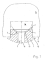
- FIG. 1 schematically shows a section of a pole piece 1 shown with a valve seat 2 and an embossing element 16.
- the state of the valve seat 2 is immediately before imaged during or during the embossing process.
- a recess 4 of the pole piece 1 or valve seat element. 1 preferably produced by means of rotation method, wherein a Overhang or ring land 5 was generated, the one Embossing surface 17 includes.
- valve seat 2 is shown schematically in FIG Embossing process shown.
- embossing was from the Supernatant or annular web 5 a deformation 6 of the pole piece. 1 generated. According to this figure it becomes clear that the Deformation 6 to a narrowing or buckling of a Valve bore 7 leads.
- embossing the valve seat 2 a Sealing surface 8 generated.
- This sealing surface 8 forms the Contact surface between the valve body 3 and the pole piece. 1
- embossing is a spherical ring as a sealing surface. 8 which has a high accuracy of the spherical Form with respect to the spherical shape of the valve body 3 has.
- the recess 4 to the shape of the valve body 3 advantageous adapted, so that a particularly dense Valve seat 2 is generated for the valve body 3.
- an optionally foreseeable recess 9 is provided of the pole piece 1, which is for receiving a seal, e.g. an elastomeric, Teflon seal or the like is trained.
- a Teflon or Elastomer seal 10 listed which is also optional can be provided. Both the elastomer seal 10 as also the unspecified seal, which in the Puncture 9 can be inserted and / or injected, can under special conditions for additional sealing of the Valve seat 2 are provided.
- the figure 2 is a magnet 11, in particular To remove ring magnet 11.
- This magnet 11 is on the pole piece 1 with the help of a stop 12 exactly localized.
- a stop 12 By the exact determination of the position of the magnet 11 and the Sealing surface 8 becomes the attractive force generated by this set for the valve body 3. This ensures a safe operation of the valve.
- the stop 12 additionally as a stop 12 for a Regelehre 14 and their Stop 13 is formed.
- embossing is using help the Regelehre 14 a highly accurate definition of the situation Sealing surface 8 in the axial direction 15 of the valve or in Direction of the valve lift of the valve body 3 set.
- the recess 4 with comparatively low accuracy among others by Turning method can be produced.
- the existing here Inaccuracies of turning, both in terms of shape the recess, as well as in relation to the outer dimensions of the Polschuhs 1 or the stop 12, etc. are when embossing, in particular due to the recupergelehre 14, in an advantageous Way reduced or eliminated.
- valves according to the invention between two pole pieces 1, a spacer according to the in State of the art listed international Applicant's patent application used.
- this Spacer By means of this Spacer are just in combination with the embossed Valve seat 2 according to the present invention a High-precision and thus also tight valve in a simple way inexpensive to produce, so depending on the application even to a final check or measurement of Tolerances of individual production steps and / or finished mounted valve can be dispensed with. Accordingly reduces the total cost of manufacturing and assembly corresponding valves according to the invention.
- the recuperative 14 by advantageous Processing of the stop 13, in particular by grinding, Polishing, etc. are made with very high accuracy. The same applies to a spacer mentioned above between the pole pieces 1 to.
Applications Claiming Priority (2)
| Application Number | Priority Date | Filing Date | Title |
|---|---|---|---|
| DE10360706 | 2003-12-19 | ||
| DE2003160706 DE10360706A1 (de) | 2003-12-19 | 2003-12-19 | Ventil und Verfahren zum Herstellen eines Ventils |
Publications (3)
| Publication Number | Publication Date |
|---|---|
| EP1548341A2 true EP1548341A2 (fr) | 2005-06-29 |
| EP1548341A3 EP1548341A3 (fr) | 2005-07-13 |
| EP1548341B1 EP1548341B1 (fr) | 2008-04-16 |
Family
ID=34530358
Family Applications (1)
| Application Number | Title | Priority Date | Filing Date |
|---|---|---|---|
| EP20040029662 Active EP1548341B1 (fr) | 2003-12-19 | 2004-12-15 | Soupape et procédé de production |
Country Status (5)
| Country | Link |
|---|---|
| US (2) | US7210494B2 (fr) |
| EP (1) | EP1548341B1 (fr) |
| CN (1) | CN100522413C (fr) |
| AT (1) | ATE392578T1 (fr) |
| DE (2) | DE10360706A1 (fr) |
Families Citing this family (16)
| Publication number | Priority date | Publication date | Assignee | Title |
|---|---|---|---|---|
| JP4528701B2 (ja) * | 2005-09-13 | 2010-08-18 | 日立オートモティブシステムズ株式会社 | 噴射弁及びオリフィスの加工方法 |
| DE602007011961D1 (de) * | 2006-10-13 | 2011-02-24 | Parker Hannifin Corp | Dreiweg-tellerventil |
| EP2108811B1 (fr) * | 2007-01-29 | 2014-07-09 | Mitsubishi Electric Corporation | Injecteur de carburant |
| DE102008055612A1 (de) | 2008-11-03 | 2010-05-06 | Thomas Magnete Gmbh | Hubkolbenpumpe |
| DE102008055608A1 (de) | 2008-11-03 | 2010-05-06 | Thomas Magnete Gmbh | Hubkolbenpumpe |
| DE102008055610A1 (de) | 2008-11-03 | 2010-05-06 | Thomas Magnete Gmbh | Hubkolbenpumpe |
| DE102008055609B4 (de) * | 2008-11-03 | 2011-12-29 | Thomas Magnete Gmbh | Hubkolbenpumpe |
| CN102313031A (zh) * | 2010-08-06 | 2012-01-11 | 高砂电气(苏州)有限公司 | 阀构件 |
| US20130221255A1 (en) * | 2012-02-29 | 2013-08-29 | Vernay Laboratories, Inc. | Magneto-rheological elastomeric fluid control armature assembly |
| DE102012106682A1 (de) * | 2012-07-24 | 2014-02-13 | Dorma Gmbh + Co. Kg | Verfahren und Vorrichtung zum Herstellen eines Ventils |
| DE102014106010A1 (de) * | 2014-04-29 | 2015-10-29 | Sig Technology Ag | Vorrichtung zur Steuerung oder Regelung der Durchflussmenge und/oder Durchflussrichtung von Fluiden |
| US11204103B2 (en) * | 2017-11-13 | 2021-12-21 | Hamilton Sundstrand Corporation | Coined seat for metal-to-metal seating |
| CN109304407B (zh) * | 2018-12-04 | 2020-11-06 | 中国航发贵州红林航空动力控制科技有限公司 | 一种阀座密封环带冲压成型方法 |
| CN111022658B (zh) * | 2019-12-12 | 2021-08-03 | 武昌船舶重工集团有限公司 | 基于具有通海阀及其传动装置的系统的加工装配方法 |
| US11242936B2 (en) * | 2020-03-16 | 2022-02-08 | Tier 1 Energy Tech, Inc. | Magnetic seat engagement in a ball check valve |
| DE102021101831A1 (de) * | 2021-01-27 | 2022-07-28 | Dionex Softron Gmbh | Ventilanordnung |
Citations (10)
| Publication number | Priority date | Publication date | Assignee | Title |
|---|---|---|---|---|
| DE3913567A1 (de) | 1989-04-25 | 1990-10-31 | Weinsberg Karosseriewerke | Windabweiser fuer kraftfahrzeuge |
| DE19701479A1 (de) | 1997-01-17 | 1998-07-23 | Bayerische Motoren Werke Ag | Vorrichtung zur Betätigung eines Windabweisers an einem Fahrzeugschiebedach |
| DE19714492A1 (de) | 1997-04-08 | 1998-10-15 | Bayerische Motoren Werke Ag | Betätigungsvorrichtung für einen Windabweiser an einem Fahrzeug-Schiebedach |
| EP0931683A2 (fr) | 1998-01-22 | 1999-07-28 | Robert Bosch Gmbh | Véhicule automobile avec déflecteur de vent pour toít coulissant |
| DE19809943A1 (de) | 1998-03-07 | 1999-09-09 | Webasto Karosseriesysteme | Fahrzeug-Windabweiser mit abhängig von der Fahrzeuggeschwindigkeit einstellbarem Aufstellgrad |
| DE19958742A1 (de) | 1999-12-07 | 2001-06-21 | Webasto Vehicle Sys Int Gmbh | Vorrichtung zur Beeinflussung der Luftströmung |
| FR2810592A1 (fr) | 2000-06-27 | 2001-12-28 | Webasto Systemes Carrosserie | Systeme de deflecteur de toit ouvrant |
| DE10146285A1 (de) | 2001-03-19 | 2002-10-02 | Webasto Vehicle Sys Int Gmbh | Fahrzeugdach |
| DE10142047A1 (de) | 2001-08-28 | 2003-03-20 | Arvinmeritor Gmbh | Windabweiser mit Betätigungselement für ein Schiebedachsystem |
| DE10210617C1 (de) | 2002-03-11 | 2003-12-04 | Webasto Vehicle Sys Int Gmbh | Fahrzeugdach |
Family Cites Families (20)
| Publication number | Priority date | Publication date | Assignee | Title |
|---|---|---|---|---|
| US3077896A (en) * | 1959-10-01 | 1963-02-19 | Archie E Weingard | Multiple seat valve |
| US3191277A (en) * | 1961-05-17 | 1965-06-29 | Clarence O Glasgow | Valve seat |
| FR1309839A (fr) * | 1961-06-13 | 1962-11-23 | Bertin & Cie | Vanne équilibrée, notamment pour gaz chauds |
| US3736640A (en) * | 1970-12-15 | 1973-06-05 | Fmc Corp | Method of forming a metal valve seat |
| FR2363044A1 (fr) * | 1976-08-27 | 1978-03-24 | Wabco Westinghouse | Soupape a bille |
| US4901754A (en) * | 1986-10-15 | 1990-02-20 | Anthony Industries, Inc. | Valve improvements |
| DE3841142C2 (de) * | 1988-12-07 | 1994-09-29 | Bosch Gmbh Robert | Einspritzventil |
| DE3939093A1 (de) * | 1989-11-25 | 1991-05-29 | Bosch Gmbh Robert | Elektromagnetisch betaetigbares kraftstoffeinspritzventil |
| US5107890A (en) * | 1990-05-03 | 1992-04-28 | Huron Products Industries, Inc. | Ball check valve |
| DE19602068C2 (de) * | 1996-01-20 | 1998-07-02 | Bosch Gmbh Robert | Verfahren und Vorrichtung zur Herstellung von rotationssymmetrischen Ventilsitzflächen mit hoher Oberflächengüte an Ventilen, insbesondere Brennstoffeinspritzventilen für Brennkraftmaschinen |
| US5954312A (en) * | 1996-01-31 | 1999-09-21 | Siemens Automotive Corporation | Groove means in a fuel injector valve seat |
| DE19631066A1 (de) * | 1996-08-01 | 1998-02-05 | Bosch Gmbh Robert | Brennstoffeinspritzventil |
| DE19653832A1 (de) * | 1996-12-21 | 1998-06-25 | Bosch Gmbh Robert | Ventil mit kombiniertem Ventilsitzkörper und Spritzlochscheibe |
| DE19726991A1 (de) * | 1997-06-25 | 1999-01-07 | Bosch Gmbh Robert | Ventil und Verfahren zur Herstellung eines Ventilsitzes für ein Ventil |
| DE19816289A1 (de) * | 1998-02-09 | 1999-08-12 | Itt Mfg Enterprises Inc | Druckventil, insbesondere für eine Kolbenpumpe |
| TR200100776T2 (tr) | 1998-09-17 | 2001-07-23 | Harald Schrott | Bir soğutma tesisatı için soğukluk üretme devresi |
| EP1128109A1 (fr) * | 2000-02-22 | 2001-08-29 | Siemens Building Technologies AG | Vanne pour dispositif de commande |
| US6543136B1 (en) * | 2000-06-29 | 2003-04-08 | Siemens Automotive Corporation | Method for improved valve seating of a fuel injector by coining and a valve made thereby |
| DE10206778A1 (de) | 2002-02-19 | 2003-08-28 | Aweco Appliance Sys Gmbh & Co | Bistabiles elektromagnetisches Ventil |
| US7744020B2 (en) * | 2003-07-21 | 2010-06-29 | Continental Automotive Systems Us, Inc. | Fuel injector including an orifice disc, and a method of forming the orifice disc including punching and shaving |
-
2003
- 2003-12-19 DE DE2003160706 patent/DE10360706A1/de not_active Withdrawn
-
2004
- 2004-12-15 AT AT04029662T patent/ATE392578T1/de not_active IP Right Cessation
- 2004-12-15 DE DE200450006836 patent/DE502004006836D1/de active Active
- 2004-12-15 EP EP20040029662 patent/EP1548341B1/fr active Active
- 2004-12-17 US US11/013,880 patent/US7210494B2/en not_active Expired - Fee Related
- 2004-12-20 CN CNB2004101016728A patent/CN100522413C/zh active Active
-
2007
- 2007-04-27 US US11/790,898 patent/US7611125B2/en active Active
Patent Citations (10)
| Publication number | Priority date | Publication date | Assignee | Title |
|---|---|---|---|---|
| DE3913567A1 (de) | 1989-04-25 | 1990-10-31 | Weinsberg Karosseriewerke | Windabweiser fuer kraftfahrzeuge |
| DE19701479A1 (de) | 1997-01-17 | 1998-07-23 | Bayerische Motoren Werke Ag | Vorrichtung zur Betätigung eines Windabweisers an einem Fahrzeugschiebedach |
| DE19714492A1 (de) | 1997-04-08 | 1998-10-15 | Bayerische Motoren Werke Ag | Betätigungsvorrichtung für einen Windabweiser an einem Fahrzeug-Schiebedach |
| EP0931683A2 (fr) | 1998-01-22 | 1999-07-28 | Robert Bosch Gmbh | Véhicule automobile avec déflecteur de vent pour toít coulissant |
| DE19809943A1 (de) | 1998-03-07 | 1999-09-09 | Webasto Karosseriesysteme | Fahrzeug-Windabweiser mit abhängig von der Fahrzeuggeschwindigkeit einstellbarem Aufstellgrad |
| DE19958742A1 (de) | 1999-12-07 | 2001-06-21 | Webasto Vehicle Sys Int Gmbh | Vorrichtung zur Beeinflussung der Luftströmung |
| FR2810592A1 (fr) | 2000-06-27 | 2001-12-28 | Webasto Systemes Carrosserie | Systeme de deflecteur de toit ouvrant |
| DE10146285A1 (de) | 2001-03-19 | 2002-10-02 | Webasto Vehicle Sys Int Gmbh | Fahrzeugdach |
| DE10142047A1 (de) | 2001-08-28 | 2003-03-20 | Arvinmeritor Gmbh | Windabweiser mit Betätigungselement für ein Schiebedachsystem |
| DE10210617C1 (de) | 2002-03-11 | 2003-12-04 | Webasto Vehicle Sys Int Gmbh | Fahrzeugdach |
Also Published As
| Publication number | Publication date |
|---|---|
| DE502004006836D1 (de) | 2008-05-29 |
| US20070246667A1 (en) | 2007-10-25 |
| DE10360706A1 (de) | 2005-07-14 |
| EP1548341B1 (fr) | 2008-04-16 |
| US7210494B2 (en) | 2007-05-01 |
| US7611125B2 (en) | 2009-11-03 |
| CN100522413C (zh) | 2009-08-05 |
| US20050139801A1 (en) | 2005-06-30 |
| ATE392578T1 (de) | 2008-05-15 |
| EP1548341A3 (fr) | 2005-07-13 |
| CN1644268A (zh) | 2005-07-27 |
Similar Documents
| Publication | Publication Date | Title |
|---|---|---|
| EP1548341B1 (fr) | Soupape et procédé de production | |
| DE602006000626T2 (de) | Elektromagnetventil mit Befestigungseinrichtung | |
| DE10150613B4 (de) | Radlagereinheit für Kraftfahrzeuge | |
| DE102017216626B3 (de) | Ventil für eine Hochdruckpumpe für ein Kraftfahrzeug und Verfahren zum Herstellen eines Ventils für eine Hochdruckpumpe | |
| DE102008033269B4 (de) | Rückschlagventil | |
| DE102011013702A1 (de) | Elektromagnetischer Aktor | |
| DE10239207A1 (de) | Elektromagnetisches Hydraulikventil, insbesondere Proportionalventil zur Steuerung einer Vorrichtung zur Drehwinkelverstellung einer Nockenwelle gegenüber einer Kurbelwelle einer Brennkraftmaschine | |
| DE102011006855A1 (de) | Schieberventil mit einem Gehäuse und einem in dem Gehäuse geführten Schieber | |
| DE102010031328B4 (de) | Magnetventil sowie Fahrerassistenzeinrichtung | |
| DE102007031855A1 (de) | Ventilpatrone für ein Magnetventil | |
| EP3078036A1 (fr) | Soupape pour système hybride hydraulique | |
| AT505294B1 (de) | Verfahren zum druckdichten verschliessen einer bohrung, sowie druckgehäuse | |
| EP1317328B1 (fr) | POINçON DE MATAGE ET UTILISATION D'UN TEL POINçON | |
| EP2519432A1 (fr) | Soupape électromagnétique et procédé de fabrication associé | |
| DE10353314B4 (de) | Rückschlagventil für eine Kraftstoffhochdruckpumpe | |
| DE102021115936A1 (de) | Kolbenkühldüse | |
| DE102016208973A1 (de) | Elektromagnetisch betätigbares Saugventil und Kraftstoff-Hochdruckpumpe | |
| DE102016212562A1 (de) | Rückschlagventil für ein Magnetventil und zugehöriges Magnetventil | |
| DE102015212860A1 (de) | Kolben-Vorrichtung, Verfahren zum Herstellen einer derartigen Kolben-Vorrichtung sowie Kolben-Zylinder-Einheit mit einer derartigen Kolben-Vorrichtung | |
| DE102019120227A1 (de) | Ventil und Vorrichtung zur Regelung von Drücken eines Strömungsmittels mit dem Ventil sowie Vorrichtung zur Sicherung des Ventils in dem Getriebebauteil | |
| DE102018124222A1 (de) | Elektromotorischer Pumpenaktor sowie Verfahren zu dessen Herstellung und Kupplung umfassend einen solchen elektromotorischen Pumpenaktor | |
| DE102006045162A1 (de) | Hydraulikblock | |
| WO2008132034A1 (fr) | Tournant sphérique d'arrêt d'un robinet à tournant sphérique et son procédé de réalisation | |
| WO2017050403A1 (fr) | Procédé de fabrication d'un élément d'accouplement pour un accouplement à griffes constitué d'une pièce de tôle épaisse et élément d'accouplement | |
| DE10064976A1 (de) | Armatur mit Anschlussadapter |
Legal Events
| Date | Code | Title | Description |
|---|---|---|---|
| PUAI | Public reference made under article 153(3) epc to a published international application that has entered the european phase |
Free format text: ORIGINAL CODE: 0009012 |
|
| PUAL | Search report despatched |
Free format text: ORIGINAL CODE: 0009013 |
|
| AK | Designated contracting states |
Kind code of ref document: A2 Designated state(s): AT BE BG CH CY CZ DE DK EE ES FI FR GB GR HU IE IS IT LI LT LU MC NL PL PT RO SE SI SK TR |
|
| AX | Request for extension of the european patent |
Extension state: AL BA HR LV MK YU |
|
| AK | Designated contracting states |
Kind code of ref document: A3 Designated state(s): AT BE BG CH CY CZ DE DK EE ES FI FR GB GR HU IE IS IT LI LT LU MC NL PL PT RO SE SI SK TR |
|
| AX | Request for extension of the european patent |
Extension state: AL BA HR LV MK YU |
|
| 17P | Request for examination filed |
Effective date: 20051110 |
|
| AKX | Designation fees paid |
Designated state(s): AT BE BG CH CY CZ DE DK EE ES FI FR GB GR HU IE IS IT LI LT LU MC NL PL PT RO SE SI SK TR |
|
| 17Q | First examination report despatched |
Effective date: 20051222 |
|
| GRAP | Despatch of communication of intention to grant a patent |
Free format text: ORIGINAL CODE: EPIDOSNIGR1 |
|
| GRAS | Grant fee paid |
Free format text: ORIGINAL CODE: EPIDOSNIGR3 |
|
| GRAA | (expected) grant |
Free format text: ORIGINAL CODE: 0009210 |
|
| AK | Designated contracting states |
Kind code of ref document: B1 Designated state(s): AT BE BG CH CY CZ DE DK EE ES FI FR GB GR HU IE IS IT LI LT LU MC NL PL PT RO SE SI SK TR |
|
| RTI1 | Title (correction) |
Free format text: VALVE AND METHOD FOR ITS PRODUCTION |
|
| REG | Reference to a national code |
Ref country code: CH Ref legal event code: EP |
|
| REG | Reference to a national code |
Ref country code: IE Ref legal event code: FG4D Free format text: LANGUAGE OF EP DOCUMENT: GERMAN |
|
| REF | Corresponds to: |
Ref document number: 502004006836 Country of ref document: DE Date of ref document: 20080529 Kind code of ref document: P |
|
| PG25 | Lapsed in a contracting state [announced via postgrant information from national office to epo] |
Ref country code: SI Free format text: LAPSE BECAUSE OF FAILURE TO SUBMIT A TRANSLATION OF THE DESCRIPTION OR TO PAY THE FEE WITHIN THE PRESCRIBED TIME-LIMIT Effective date: 20080416 |
|
| NLV1 | Nl: lapsed or annulled due to failure to fulfill the requirements of art. 29p and 29m of the patents act | ||
| PG25 | Lapsed in a contracting state [announced via postgrant information from national office to epo] |
Ref country code: ES Free format text: LAPSE BECAUSE OF FAILURE TO SUBMIT A TRANSLATION OF THE DESCRIPTION OR TO PAY THE FEE WITHIN THE PRESCRIBED TIME-LIMIT Effective date: 20080727 Ref country code: BG Free format text: LAPSE BECAUSE OF FAILURE TO SUBMIT A TRANSLATION OF THE DESCRIPTION OR TO PAY THE FEE WITHIN THE PRESCRIBED TIME-LIMIT Effective date: 20080716 Ref country code: FI Free format text: LAPSE BECAUSE OF FAILURE TO SUBMIT A TRANSLATION OF THE DESCRIPTION OR TO PAY THE FEE WITHIN THE PRESCRIBED TIME-LIMIT Effective date: 20080416 Ref country code: NL Free format text: LAPSE BECAUSE OF FAILURE TO SUBMIT A TRANSLATION OF THE DESCRIPTION OR TO PAY THE FEE WITHIN THE PRESCRIBED TIME-LIMIT Effective date: 20080416 Ref country code: PT Free format text: LAPSE BECAUSE OF FAILURE TO SUBMIT A TRANSLATION OF THE DESCRIPTION OR TO PAY THE FEE WITHIN THE PRESCRIBED TIME-LIMIT Effective date: 20080916 |
|
| REG | Reference to a national code |
Ref country code: IE Ref legal event code: FD4D |
|
| PG25 | Lapsed in a contracting state [announced via postgrant information from national office to epo] |
Ref country code: IS Free format text: LAPSE BECAUSE OF FAILURE TO SUBMIT A TRANSLATION OF THE DESCRIPTION OR TO PAY THE FEE WITHIN THE PRESCRIBED TIME-LIMIT Effective date: 20080816 |
|
| ET | Fr: translation filed | ||
| PG25 | Lapsed in a contracting state [announced via postgrant information from national office to epo] |
Ref country code: DK Free format text: LAPSE BECAUSE OF FAILURE TO SUBMIT A TRANSLATION OF THE DESCRIPTION OR TO PAY THE FEE WITHIN THE PRESCRIBED TIME-LIMIT Effective date: 20080416 Ref country code: SE Free format text: LAPSE BECAUSE OF FAILURE TO SUBMIT A TRANSLATION OF THE DESCRIPTION OR TO PAY THE FEE WITHIN THE PRESCRIBED TIME-LIMIT Effective date: 20080716 Ref country code: LT Free format text: LAPSE BECAUSE OF FAILURE TO SUBMIT A TRANSLATION OF THE DESCRIPTION OR TO PAY THE FEE WITHIN THE PRESCRIBED TIME-LIMIT Effective date: 20080416 Ref country code: IE Free format text: LAPSE BECAUSE OF FAILURE TO SUBMIT A TRANSLATION OF THE DESCRIPTION OR TO PAY THE FEE WITHIN THE PRESCRIBED TIME-LIMIT Effective date: 20080416 Ref country code: CZ Free format text: LAPSE BECAUSE OF FAILURE TO SUBMIT A TRANSLATION OF THE DESCRIPTION OR TO PAY THE FEE WITHIN THE PRESCRIBED TIME-LIMIT Effective date: 20080416 |
|
| PLBE | No opposition filed within time limit |
Free format text: ORIGINAL CODE: 0009261 |
|
| STAA | Information on the status of an ep patent application or granted ep patent |
Free format text: STATUS: NO OPPOSITION FILED WITHIN TIME LIMIT |
|
| PG25 | Lapsed in a contracting state [announced via postgrant information from national office to epo] |
Ref country code: SK Free format text: LAPSE BECAUSE OF FAILURE TO SUBMIT A TRANSLATION OF THE DESCRIPTION OR TO PAY THE FEE WITHIN THE PRESCRIBED TIME-LIMIT Effective date: 20080416 Ref country code: RO Free format text: LAPSE BECAUSE OF FAILURE TO SUBMIT A TRANSLATION OF THE DESCRIPTION OR TO PAY THE FEE WITHIN THE PRESCRIBED TIME-LIMIT Effective date: 20080416 |
|
| 26N | No opposition filed |
Effective date: 20090119 |
|
| PG25 | Lapsed in a contracting state [announced via postgrant information from national office to epo] |
Ref country code: EE Free format text: LAPSE BECAUSE OF FAILURE TO SUBMIT A TRANSLATION OF THE DESCRIPTION OR TO PAY THE FEE WITHIN THE PRESCRIBED TIME-LIMIT Effective date: 20080416 |
|
| BERE | Be: lapsed |
Owner name: AWECO APPLIANCE SYSTEMS G.M.B.H. & CO. KG Effective date: 20081231 |
|
| PG25 | Lapsed in a contracting state [announced via postgrant information from national office to epo] |
Ref country code: MC Free format text: LAPSE BECAUSE OF NON-PAYMENT OF DUE FEES Effective date: 20081231 |
|
| REG | Reference to a national code |
Ref country code: CH Ref legal event code: PL |
|
| GBPC | Gb: european patent ceased through non-payment of renewal fee |
Effective date: 20081215 |
|
| PG25 | Lapsed in a contracting state [announced via postgrant information from national office to epo] |
Ref country code: CY Free format text: LAPSE BECAUSE OF FAILURE TO SUBMIT A TRANSLATION OF THE DESCRIPTION OR TO PAY THE FEE WITHIN THE PRESCRIBED TIME-LIMIT Effective date: 20080416 Ref country code: BE Free format text: LAPSE BECAUSE OF NON-PAYMENT OF DUE FEES Effective date: 20081231 |
|
| REG | Reference to a national code |
Ref country code: FR Ref legal event code: ST Effective date: 20090831 |
|
| PG25 | Lapsed in a contracting state [announced via postgrant information from national office to epo] |
Ref country code: LI Free format text: LAPSE BECAUSE OF NON-PAYMENT OF DUE FEES Effective date: 20081231 Ref country code: CH Free format text: LAPSE BECAUSE OF NON-PAYMENT OF DUE FEES Effective date: 20081231 |
|
| PG25 | Lapsed in a contracting state [announced via postgrant information from national office to epo] |
Ref country code: PL Free format text: LAPSE BECAUSE OF FAILURE TO SUBMIT A TRANSLATION OF THE DESCRIPTION OR TO PAY THE FEE WITHIN THE PRESCRIBED TIME-LIMIT Effective date: 20080416 Ref country code: GB Free format text: LAPSE BECAUSE OF NON-PAYMENT OF DUE FEES Effective date: 20081215 |
|
| PGFP | Annual fee paid to national office [announced via postgrant information from national office to epo] |
Ref country code: TR Payment date: 20091204 Year of fee payment: 6 |
|
| PG25 | Lapsed in a contracting state [announced via postgrant information from national office to epo] |
Ref country code: FR Free format text: LAPSE BECAUSE OF NON-PAYMENT OF DUE FEES Effective date: 20081231 |
|
| PG25 | Lapsed in a contracting state [announced via postgrant information from national office to epo] |
Ref country code: AT Free format text: LAPSE BECAUSE OF NON-PAYMENT OF DUE FEES Effective date: 20081215 |
|
| PG25 | Lapsed in a contracting state [announced via postgrant information from national office to epo] |
Ref country code: LU Free format text: LAPSE BECAUSE OF NON-PAYMENT OF DUE FEES Effective date: 20081215 Ref country code: HU Free format text: LAPSE BECAUSE OF FAILURE TO SUBMIT A TRANSLATION OF THE DESCRIPTION OR TO PAY THE FEE WITHIN THE PRESCRIBED TIME-LIMIT Effective date: 20081017 |
|
| PG25 | Lapsed in a contracting state [announced via postgrant information from national office to epo] |
Ref country code: GR Free format text: LAPSE BECAUSE OF FAILURE TO SUBMIT A TRANSLATION OF THE DESCRIPTION OR TO PAY THE FEE WITHIN THE PRESCRIBED TIME-LIMIT Effective date: 20080717 |
|
| REG | Reference to a national code |
Ref country code: DE Ref legal event code: R082 Ref document number: 502004006836 Country of ref document: DE Representative=s name: PATENTANWAELTE VON KREISLER, SELTING, WERNER, DE |
|
| REG | Reference to a national code |
Ref country code: DE Ref legal event code: R082 Ref document number: 502004006836 Country of ref document: DE Representative=s name: DOMPATENT VON KREISLER SELTING WERNER - PARTNE, DE Effective date: 20120327 Ref country code: DE Ref legal event code: R081 Ref document number: 502004006836 Country of ref document: DE Owner name: ZHEJIANG SANHUA CO., LTD., CHENGGUAN TOWN, CN Free format text: FORMER OWNER: AWECO APPLIANCE SYSTEMS GMBH & CO. KG, 88099 NEUKIRCH, DE Effective date: 20120327 Ref country code: DE Ref legal event code: R082 Ref document number: 502004006836 Country of ref document: DE Representative=s name: VON KREISLER SELTING WERNER - PARTNERSCHAFT VO, DE Effective date: 20120327 Ref country code: DE Ref legal event code: R081 Ref document number: 502004006836 Country of ref document: DE Owner name: ZHEJIANG SANHUA CO., LTD., CN Free format text: FORMER OWNER: AWECO APPLIANCE SYSTEMS GMBH & CO. KG, 88099 NEUKIRCH, DE Effective date: 20120327 Ref country code: DE Ref legal event code: R082 Ref document number: 502004006836 Country of ref document: DE Representative=s name: VON KREISLER SELTING WERNER, DE Effective date: 20120327 Ref country code: DE Ref legal event code: R081 Ref document number: 502004006836 Country of ref document: DE Owner name: ZHEJIANG SANHUA INTELLIGENT CONTROLS CO., LTD., CN Free format text: FORMER OWNER: AWECO APPLIANCE SYSTEMS GMBH & CO. KG, 88099 NEUKIRCH, DE Effective date: 20120327 |
|
| PG25 | Lapsed in a contracting state [announced via postgrant information from national office to epo] |
Ref country code: TR Free format text: LAPSE BECAUSE OF NON-PAYMENT OF DUE FEES Effective date: 20101215 |
|
| REG | Reference to a national code |
Ref country code: DE Ref legal event code: R081 Ref document number: 502004006836 Country of ref document: DE Owner name: ZHEJIANG SANHUA INTELLIGENT CONTROLS CO., LTD., CN Free format text: FORMER OWNER: ZHEJIANG SANHUA CO., LTD., CHENGGUAN TOWN, XINCHANG COUNTY, CN Ref country code: DE Ref legal event code: R082 Ref document number: 502004006836 Country of ref document: DE Representative=s name: DOMPATENT VON KREISLER SELTING WERNER - PARTNE, DE |
|
| P01 | Opt-out of the competence of the unified patent court (upc) registered |
Effective date: 20230519 |
|
| PGFP | Annual fee paid to national office [announced via postgrant information from national office to epo] |
Ref country code: IT Payment date: 20231212 Year of fee payment: 20 Ref country code: DE Payment date: 20231208 Year of fee payment: 20 |