EP1548296B1 - Dispositif de liaison coaxiale d'une première barre à une deuxième barre - Google Patents
Dispositif de liaison coaxiale d'une première barre à une deuxième barre Download PDFInfo
- Publication number
- EP1548296B1 EP1548296B1 EP04003890A EP04003890A EP1548296B1 EP 1548296 B1 EP1548296 B1 EP 1548296B1 EP 04003890 A EP04003890 A EP 04003890A EP 04003890 A EP04003890 A EP 04003890A EP 1548296 B1 EP1548296 B1 EP 1548296B1
- Authority
- EP
- European Patent Office
- Prior art keywords
- component
- rod
- plug
- wedge face
- face
- Prior art date
- Legal status (The legal status is an assumption and is not a legal conclusion. Google has not performed a legal analysis and makes no representation as to the accuracy of the status listed.)
- Expired - Lifetime
Links
- 241000549194 Euonymus europaeus Species 0.000 claims description 2
- 150000001875 compounds Chemical class 0.000 description 2
- 238000003780 insertion Methods 0.000 description 2
- 230000037431 insertion Effects 0.000 description 2
- 230000036316 preload Effects 0.000 description 2
- 230000005540 biological transmission Effects 0.000 description 1
- 230000015572 biosynthetic process Effects 0.000 description 1
- 239000000463 material Substances 0.000 description 1
- 230000013011 mating Effects 0.000 description 1
- 238000000034 method Methods 0.000 description 1
- 230000000149 penetrating effect Effects 0.000 description 1
- 230000035515 penetration Effects 0.000 description 1
- 230000002093 peripheral effect Effects 0.000 description 1
- 238000002360 preparation method Methods 0.000 description 1
- 238000005096 rolling process Methods 0.000 description 1
- 239000007787 solid Substances 0.000 description 1
- 230000003068 static effect Effects 0.000 description 1
- 239000013585 weight reducing agent Substances 0.000 description 1
Images

Classifications
-
- F—MECHANICAL ENGINEERING; LIGHTING; HEATING; WEAPONS; BLASTING
- F16—ENGINEERING ELEMENTS AND UNITS; GENERAL MEASURES FOR PRODUCING AND MAINTAINING EFFECTIVE FUNCTIONING OF MACHINES OR INSTALLATIONS; THERMAL INSULATION IN GENERAL
- F16B—DEVICES FOR FASTENING OR SECURING CONSTRUCTIONAL ELEMENTS OR MACHINE PARTS TOGETHER, e.g. NAILS, BOLTS, CIRCLIPS, CLAMPS, CLIPS OR WEDGES; JOINTS OR JOINTING
- F16B7/00—Connections of rods or tubes, e.g. of non-circular section, mutually, including resilient connections
- F16B7/22—Connections of rods or tubes, e.g. of non-circular section, mutually, including resilient connections using hooks or like elements
Definitions
- the present invention relates to a device for coaxial connection of a first rod with a second rod according to the preamble of claim 1 and from the document FR-E-91217 known.
- rods of the type mentioned in the beginning are always used when a given length of a rod standardized in its length turns out to be smaller than the rod length required for a particular rod insert.
- rods are often designed as so-called racks, which can either be formed from a solid profile or - usually for reasons of weight reduction - from a regularly formed as a profile tube tube material, which is provided with a rack profile attachment.
- the present invention is therefore an object of the invention to provide a connection between two racks, which proves to be particularly secure as kink-proof and the coaxiality of the connected rods.
- the first rod is provided in a connecting region with a plug part and the second rod in the connecting region with a socket part for receiving the plug part.
- On the plug part is a first inclined to the longitudinal axis of the rods, fixed wedge surface and the socket part a second inclined to the longitudinal axis of the rods and movable transversely to the longitudinal axis wedge surface and cooperating with the second wedge surface feed device, wherein the fixed wedge surface on the socket part and the movable wedge surface can also be provided on the plug part.
- the wedge surfaces cooperate in such a way that a movement of the second wedge surface against the first wedge surface by means of the feed device causes an advancing movement of the male part into the female part until the first axial abutment surface of the first pole abuts against a second axial abutment surface of the second pole.
- the plug-socket design of the connecting device according to the invention leads, together with the result of a tensile stress against each other biased rods to a particularly kink-proof design of the compound.
- the male-female version makes it easy to secure the coaxial alignment of the interconnected rods.
- the plug-socket design in conjunction with the mutually prestressed arrangement of the rods, also ensures a particular dimensional stability of the rod assembly over the connection region, so that the orientation of the rod surfaces is maintained even with an occurring transverse load and thus, in particular, no discontinuity in the surface inclination occurs.
- the wedge surface is according to the invention on the plug part of the first rod formed on a drawbar, which is arranged on a free end face of the plug part, and the wedge surface on the socket part is designed to engage in the towing eye and radially movable by means of the feed device hook device.
- the wedge surface is formed on the longitudinal axis arranged on the drawbar eye as a pitched roof-shaped double wedge surface and the hook means two provided with a respective wedge surface hook has, which are diametrically deliverable on a common feed axis and engageable with the drawbar, the axial preload force necessary to secure the axial connection can be distributed over several hooks, so that the compound is characterized by a high reliability during operation.
- the arrangement of the spindle ends penetrating the outer wall of the bushing part allows easy access from outside to the spindle for carrying out the advancing movement. Due to the opposing thread orientation of the spindle portions, this access can be made to both the one end and the other end of the spindle to perform the delivery and to establish the kink-proof connection between the rods.
- the spindle ends are countersunk or flush-mounted in the outer wall of the socket part, so that the outer wall has no possible obstacles to overrun, which could hinder in particular a rolling process on the outer wall, such as a transmission.
- the spindle ends are provided on the front side with a trained as a square socket tool seat, the actuation the delivery, so the preparation of the connection between the two rods, using the simplest tools, such as a Einsteckkurbel done.
- the plug part and the socket part are provided with a pair of mating radial relative positioning, so that it can be ensured in a simple manner that the teeth of a rod with exactly the teeth of the other rod is aligned.
- the connecting device can be used particularly advantageously if the plug part and the socket part are each arranged on a rod designed as a rack.
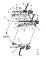
- FIG. 1 shows a container 10 designed as a cabin in the present case, which is provided in its corners with corner fastenings 11 which serve to connect container lifting and transporting devices 12.
- the container lifting and transport devices 12 are connected via a support arm device 13 with two corner fasteners 11 at a high edge 14 of the container 10.
- the support arm devices 13 are each connected to a rack lifting device 15 which actuates a lifting movement of the container 10 via a crank drive 16.
- the Zahnstangenhub coupleden 15 are provided at its lower end with a mountable wheel device 17.
- the toothed rack lifting devices 15 each have a lifting toothed rack 20 composed of a base rack 18 and a toothed rack extension 19.
- the base rack 18 and the rack extension 19 have in the present Case in each case a corpus 21 or 22 from a square tube, which are each equipped on a crank mechanism 16 facing the outer wall with a rack profile 23 and 24 respectively.
- the base rack 18 and the rack extension 19 are interconnected by means of a connection device 26 such that the rack profiles 23, 24 are arranged in alignment with each other while maintaining a matching rack module m.
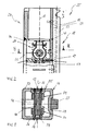
- FIG. 2 shows a socket part 27 formed in the connection area 25 on the base rack 18, which in the present case is designed as a weld-on bush and is connected to the corpus 21 of the rack base 18.
- a hook device 28 On the female part 27 and in the present embodiment below the female part 27 is a hook device 28, which, as can be seen from a synopsis of Figs. 3 and 6 , two arranged on a spindle 29 hook 30, 31 has.
- the spindle 29 defines a feed axis 32, which intersects a longitudinal axis 33 of the bushing part 27 and the base rack 18.
- the spindle 29 is mounted at its ends in plain bearings 34, 35, which are inserted in opposite walls 36, 37 of the corpus 21. Furthermore, the ends of the spindle 29 are arranged substantially flush in the outer surface of the walls 36, 37 and each formed as a square socket 38, 39.
- the spindle 29 has two respective hooks 30 and 31 associated with spindle sections 40, 41, which have an opposite thread orientation, such that in the present case, the hook 30 associated threaded portion 40th is designed as a right-hand thread and the hook 31 associated threaded portion 41 is formed as a left-hand thread.
- the hooks 30, 31 each have one with the associated threaded portion 40 and 41, respectively located threaded sleeve 42, 43, facing the connecting portion 25 each have a hook extension 44 and 45 at its periphery.
- a wedge surface 59 or 60 is respectively formed on the underside, which are employed to the feed axis 32 of the hook device 28 by the angle ⁇ .
- the hook extensions 44 and 45 are guided laterally by pins 46, 47, such that upon rotation of an inserted into the inner square 38 of the spindle 29, not shown here square of a tool in a counterclockwise direction Delivery of the hooks 30, 31 in the direction of the longitudinal axis 33 at a constant orientation of the hook extensions 44, 45 takes place.
- a guidance of the hook extensions 44, 45 can also take place by sliding hook guide surfaces 63 formed on the hooks 30, 31 on a stop plate 64 arranged below the hooks 30, 31.
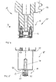
- FIGS. 4 and 5 show a plug part 48 formed in the connection region 25 on the rack extension 19, which in the present case is formed from an insertion pin formed in one piece on the body 22 of the rack extension 19.
- the plug part 48 is provided with a here U-shaped drawbar eye 50, which is bolted to the end face 49.
- the drawbar eye 50 is aligned on the end face 49 such that a ridge edge 51 of a saddle-roof-shaped double wedge surface 52 intersects the longitudinal axis 33 of the plug part 48 and the rack extension 19 and the drawbar eye is arranged symmetrically to the longitudinal axis 33, as shown in FIG .
- FIG. 6 shows the rack extension 19 used with the plug part 48 in the socket part 27 of the base rack 18.
- the drawbar 50 of the plug part 48 is located between the hooks 30, 31 of the hook part 28 arranged on the socket part 27 arranged.
- There is one at the Rack extension 19 adjacent the plug member 48 formed abutment surface 53 on a formed by the end face of the socket member 27 stop surface 54 and thus defines an axial engagement length L corresponding to the axial distance of the ridge edge 51 of the double wedge surface 52 of the stop surface 54.
- Figs. 2 and 5 in conjunction with Fig. 6 is to define the radial relative positioning shown in Fig.
- a cylindrical pin 56 is provided, which engages in an axially formed in a peripheral surface 57 of the male part guide groove 58 and during the insertion of the male part 48 in the female part 27 maintains a radial relative positioning, as shown in Fig. 6 .
- a square of the square 29 of the spindle 29 is shown in FIG used for example as a Einsteckkurbel tool and the spindle 29 is rotated clockwise.
- the hooks 30, 31 are moved uniformly with their hook extensions 44, 45 into engagement with the drawbar eye 50.
- rack extension 19 may be a formed according to the plug member 48, not shown here Einsteckkappe are provided, which is locked in the same manner as the plug member 48 via the hook means 28 with the base rack 18 and prevents ingress of dirt into the socket part 27.
- a radial projection of the plug cap can simultaneously serve as a stroke limiter, which prevents in the lifting operation that the lifting gear moves beyond the free end of the base rack 18.
Landscapes
- Engineering & Computer Science (AREA)
- General Engineering & Computer Science (AREA)
- Mechanical Engineering (AREA)
- Manufacturing Of Electrical Connectors (AREA)
- Vehicle Body Suspensions (AREA)
- Fluid-Damping Devices (AREA)
- Surgical Instruments (AREA)
- Earth Drilling (AREA)
- Transmission Devices (AREA)
Claims (7)
- Dispositif pour la connexion coaxiale d'une première barre (19) à une deuxième barre (18), la première barre étant munie d'une pièce à fiche (48) dans une zone de connexion (25), et la deuxième barre d'une pièce à prise (27) dans la zone de connexion pour le logement de la pièce à fiche, une première surface en coin (61, 62) fixe inclinée vers l'axe longitudinal (33) des barres étant prévue sur la pièce à fiche ou la pièce à prise, et une deuxième surface en coin (59, 60) inclinée vers l'axe longitudinal des barres et déplaçable perpendiculairement à l'axe longitudinal sur la pièce à fiche ou la pièce à prise, ainsi qu'un dispositif d'avance (29) coopérant avec la deuxième surface en coin de manière qu'un déplacement de la deuxième surface en coin vers la première surface en coin au moyen du dispositif d'avance provoque un mouvement d'avance de la pièce à fiche dans la pièce à prise jusqu'à l'application, avec précontrainte, d'une première surface de butée axiale (53) de la première barre contre une deuxième surface de butée axiale (54) de la deuxième barre,
caractérisé en ce que
la surface en coin (61, 62) sur la pièce à fiche (48) de la première barre (19) est formée sur un anneau de traction (50) disposé sur une surface frontale libre (49) de la pièce à fiche, et en ce que la surface en coin (59, 60) sur la pièce à prise (27) est formée sur un dispositif à crochets (28) prévu pour s'engager dans l'anneau de traction et radialement déplaçable au moyen du dispositif d'avance (29). - Dispositif selon la revendication 1,
caractérisé en ce que
la surface en coin (61, 62) sur l'anneau de traction (50) disposé sur l'axe longitudinal (33) est réalisée sous forme de surface de double coins en forme de toit à deux pentes, et en ce que le dispositif à crochets (28) comporte deux crochets (30, 31) pourvus chacun d'une surface en coin (59, 60), lesquels peuvent être réglés diamétralement sur un axe d'avance commun (32) et être déplacés engagés dans l'anneau de traction. - Dispositif selon la revendication 2,
caractérisé en ce que
les crochets (30, 31) du dispositif à crochets (28) sont disposés sur un arbre commun (29) dont les extrémités traversent une paroi extérieure de la pièce à prise (27) et présentant des parties d'arbre (40, 41) affectées chacune à un crochet et avec des orientations inverses de filets. - Dispositif selon la revendication 3,
caractérisé en ce que
les extrémités d'arbres sont frontalement munies d'un siège d'outil réalisé sous la forme d'un carré conducteur femelle (38, 39). - Dispositif selon l'une des revendications précédentes,
caractérisé en ce que
la pièce à fiche (48) et la pièce à prise (27) sont munies d'une paire d'engrènements (56, 58) pour leur positionnement radial relatif. - Dispositif selon l'une des revendications précédentes,
caractérisé en ce que
la pièce à fiche (48) et la pièce à prise (27) sont respectivement disposées sur une barre réalisée sous forme d'une crémaillère (18, 19). - Dispositif selon la revendication 6,
caractérisé en ce que
la pièce à prise (27) est réalisée sur une base de la crémaillère (18), et la pièce à fiche sur une rallonge de la crémaillère (19).
Applications Claiming Priority (2)
| Application Number | Priority Date | Filing Date | Title |
|---|---|---|---|
| DE10361125A DE10361125B4 (de) | 2003-12-22 | 2003-12-22 | Vorrichtung zur koaxialen Verbindung einer ersten Stange mit einer zweiten Stange |
| DE10361125 | 2003-12-22 |
Publications (2)
| Publication Number | Publication Date |
|---|---|
| EP1548296A1 EP1548296A1 (fr) | 2005-06-29 |
| EP1548296B1 true EP1548296B1 (fr) | 2006-06-07 |
Family
ID=34530393
Family Applications (1)
| Application Number | Title | Priority Date | Filing Date |
|---|---|---|---|
| EP04003890A Expired - Lifetime EP1548296B1 (fr) | 2003-12-22 | 2004-02-20 | Dispositif de liaison coaxiale d'une première barre à une deuxième barre |
Country Status (3)
| Country | Link |
|---|---|
| EP (1) | EP1548296B1 (fr) |
| AT (1) | ATE329162T1 (fr) |
| DE (2) | DE10361125B4 (fr) |
Families Citing this family (1)
| Publication number | Priority date | Publication date | Assignee | Title |
|---|---|---|---|---|
| DE102006014540B4 (de) * | 2006-03-24 | 2010-07-29 | Atlanta Antriebssysteme E. Seidenspinner Gmbh & Co. Kg | Einstellvorrichtung für die Montage von Zahnstangen |
Family Cites Families (6)
| Publication number | Priority date | Publication date | Assignee | Title |
|---|---|---|---|---|
| FR91271E (fr) * | 1965-10-25 | 1968-05-17 | Procédé et dispositif pour le raccordement bout à bout de deux objets allongés axialement, par exemple de deux objets cylindriques | |
| NO116451L (fr) * | 1966-02-21 | 1900-01-01 | ||
| SE442960B (sv) * | 1980-09-05 | 1986-02-10 | Gearmek Hb | Linjert styrd maskindel |
| AT389153B (de) * | 1986-02-28 | 1989-10-25 | Kohlhauser Gerhard | Verbindungselement fuer zwei tragteile |
| DE4336282A1 (de) * | 1993-10-25 | 1995-04-27 | Kreusel Magda | Verbindungselement für zwei sich kreuzende Rohre |
| DE29723560U1 (de) * | 1997-09-10 | 1998-10-08 | RK Rose + Krieger GmbH & Co. KG Verbindungs- und Positioniersysteme, 32423 Minden | Durch einen Eckverbinder lösbar miteinander verbundene, winklig zueinander stehende Profilstäbe |
-
2003
- 2003-12-22 DE DE10361125A patent/DE10361125B4/de not_active Expired - Fee Related
-
2004
- 2004-02-20 EP EP04003890A patent/EP1548296B1/fr not_active Expired - Lifetime
- 2004-02-20 DE DE502004000705T patent/DE502004000705D1/de not_active Expired - Lifetime
- 2004-02-20 AT AT04003890T patent/ATE329162T1/de not_active IP Right Cessation
Also Published As
| Publication number | Publication date |
|---|---|
| DE10361125B4 (de) | 2005-11-10 |
| ATE329162T1 (de) | 2006-06-15 |
| EP1548296A1 (fr) | 2005-06-29 |
| DE10361125A1 (de) | 2005-07-21 |
| DE502004000705D1 (de) | 2006-07-20 |
Similar Documents
| Publication | Publication Date | Title |
|---|---|---|
| DE69413582T2 (de) | Hakenschnellkupplung | |
| DE68913632T2 (de) | Motorisch verstellbare Sitzgleiteinrichtung. | |
| DE69804149T2 (de) | Verriegelungshebelmechanismus für Verbinder | |
| DE1946651A1 (de) | Spanner fuer endlose Kraftuebertragungsglieder,insbesondere fuer Ketten | |
| EP4357627B1 (fr) | Dispositif de compensation de tolérance | |
| DE69722198T2 (de) | Kettentrieb und kette dafür | |
| DE60312282T2 (de) | Gabelkopf- und Antriebswelle Struktur einer Gelenkverbindung | |
| DE3603140A1 (de) | Vorrichtung zur stufenweisen hoehenverstellung eines befestigungs- oder umlenkpunktes fuer einen sicherheitsgurt o. dgl. | |
| EP2891826A2 (fr) | Entraînement linéaire électromotorisé | |
| EP0004374A1 (fr) | Moyen de liaison de deux profilés | |
| EP1548296B1 (fr) | Dispositif de liaison coaxiale d'une première barre à une deuxième barre | |
| DE102014111436B4 (de) | Kupplungsanordnung, insbesondere Rohrkupplung | |
| EP3699385B1 (fr) | Joint automatique d'étanchéité de porte doté d'au moins un moyen de maintien, d'au moins un mécanisme de ciseaux pourvu de deux éléments de ciseaux et d'une bande d'étanchéité | |
| EP0237635A1 (fr) | Palier pour coupler des arbres enrouleurs avec un arbre menant | |
| EP3334635B1 (fr) | Dispositif de sécurité pour un ensemble d'arbres et procédé permettant de limiter temporairement la liberté de mouvement d'un joint de cardan | |
| DE102022105527A1 (de) | Gehäuse für eine elektrische Anschlussklemme oder eine elektrische Steckverbindung | |
| DE102019106613B4 (de) | Verbindungsvorrichtung | |
| DE202009015392U1 (de) | Steckverbinder für Rohre | |
| DE10341606B4 (de) | Schlüsselanordnung | |
| DE102021203698A1 (de) | Spannvorrichtung | |
| WO2022017766A1 (fr) | Agencement d'arbre et direction dotée d'un agencement d'arbre | |
| DE19942821B4 (de) | Treibstangensystem für Fenster, Türen und dergleichen | |
| DE102011003698B4 (de) | Spindelantrieb | |
| DE102006048855B4 (de) | Verbindungsanordnung | |
| DE102020105318A1 (de) | Zahnstangenlenkung |
Legal Events
| Date | Code | Title | Description |
|---|---|---|---|
| PUAI | Public reference made under article 153(3) epc to a published international application that has entered the european phase |
Free format text: ORIGINAL CODE: 0009012 |
|
| AK | Designated contracting states |
Kind code of ref document: A1 Designated state(s): AT BE BG CH CY CZ DE DK EE ES FI FR GB GR HU IE IT LI LU MC NL PT RO SE SI SK TR |
|
| AX | Request for extension of the european patent |
Extension state: AL LT LV MK |
|
| 17P | Request for examination filed |
Effective date: 20050719 |
|
| GRAP | Despatch of communication of intention to grant a patent |
Free format text: ORIGINAL CODE: EPIDOSNIGR1 |
|
| AKX | Designation fees paid |
Designated state(s): AT BE BG CH CY CZ DE DK EE ES FI FR GB GR HU IE IT LI LU MC NL PT RO SE SI SK TR |
|
| AXX | Extension fees paid |
Extension state: LT Payment date: 20050719 Extension state: AL Payment date: 20050719 Extension state: MK Payment date: 20050719 Extension state: LV Payment date: 20050719 |
|
| GRAS | Grant fee paid |
Free format text: ORIGINAL CODE: EPIDOSNIGR3 |
|
| GRAA | (expected) grant |
Free format text: ORIGINAL CODE: 0009210 |
|
| AK | Designated contracting states |
Kind code of ref document: B1 Designated state(s): AT BE BG CH CY CZ DE DK EE ES FI FR GB GR HU IE IT LI LU MC NL PT RO SE SI SK TR |
|
| AX | Request for extension of the european patent |
Extension state: AL LT LV MK |
|
| PG25 | Lapsed in a contracting state [announced via postgrant information from national office to epo] |
Ref country code: IT Free format text: LAPSE BECAUSE OF FAILURE TO SUBMIT A TRANSLATION OF THE DESCRIPTION OR TO PAY THE FEE WITHIN THE PRESCRIBED TIME-LIMIT;WARNING: LAPSES OF ITALIAN PATENTS WITH EFFECTIVE DATE BEFORE 2007 MAY HAVE OCCURRED AT ANY TIME BEFORE 2007. THE CORRECT EFFECTIVE DATE MAY BE DIFFERENT FROM THE ONE RECORDED. Effective date: 20060607 Ref country code: NL Free format text: LAPSE BECAUSE OF FAILURE TO SUBMIT A TRANSLATION OF THE DESCRIPTION OR TO PAY THE FEE WITHIN THE PRESCRIBED TIME-LIMIT Effective date: 20060607 Ref country code: IE Free format text: LAPSE BECAUSE OF FAILURE TO SUBMIT A TRANSLATION OF THE DESCRIPTION OR TO PAY THE FEE WITHIN THE PRESCRIBED TIME-LIMIT Effective date: 20060607 Ref country code: SK Free format text: LAPSE BECAUSE OF FAILURE TO SUBMIT A TRANSLATION OF THE DESCRIPTION OR TO PAY THE FEE WITHIN THE PRESCRIBED TIME-LIMIT Effective date: 20060607 Ref country code: RO Free format text: LAPSE BECAUSE OF FAILURE TO SUBMIT A TRANSLATION OF THE DESCRIPTION OR TO PAY THE FEE WITHIN THE PRESCRIBED TIME-LIMIT Effective date: 20060607 Ref country code: FI Free format text: LAPSE BECAUSE OF FAILURE TO SUBMIT A TRANSLATION OF THE DESCRIPTION OR TO PAY THE FEE WITHIN THE PRESCRIBED TIME-LIMIT Effective date: 20060607 Ref country code: CZ Free format text: LAPSE BECAUSE OF FAILURE TO SUBMIT A TRANSLATION OF THE DESCRIPTION OR TO PAY THE FEE WITHIN THE PRESCRIBED TIME-LIMIT Effective date: 20060607 Ref country code: SI Free format text: LAPSE BECAUSE OF FAILURE TO SUBMIT A TRANSLATION OF THE DESCRIPTION OR TO PAY THE FEE WITHIN THE PRESCRIBED TIME-LIMIT Effective date: 20060607 |
|
| REG | Reference to a national code |
Ref country code: GB Ref legal event code: FG4D Free format text: NOT ENGLISH |
|
| REG | Reference to a national code |
Ref country code: CH Ref legal event code: EP |
|
| REG | Reference to a national code |
Ref country code: IE Ref legal event code: FG4D Free format text: LANGUAGE OF EP DOCUMENT: GERMAN |
|
| REF | Corresponds to: |
Ref document number: 502004000705 Country of ref document: DE Date of ref document: 20060720 Kind code of ref document: P |
|
| GBT | Gb: translation of ep patent filed (gb section 77(6)(a)/1977) |
Effective date: 20060726 |
|
| PG25 | Lapsed in a contracting state [announced via postgrant information from national office to epo] |
Ref country code: SE Free format text: LAPSE BECAUSE OF FAILURE TO SUBMIT A TRANSLATION OF THE DESCRIPTION OR TO PAY THE FEE WITHIN THE PRESCRIBED TIME-LIMIT Effective date: 20060907 Ref country code: DK Free format text: LAPSE BECAUSE OF FAILURE TO SUBMIT A TRANSLATION OF THE DESCRIPTION OR TO PAY THE FEE WITHIN THE PRESCRIBED TIME-LIMIT Effective date: 20060907 |
|
| PG25 | Lapsed in a contracting state [announced via postgrant information from national office to epo] |
Ref country code: ES Free format text: LAPSE BECAUSE OF FAILURE TO SUBMIT A TRANSLATION OF THE DESCRIPTION OR TO PAY THE FEE WITHIN THE PRESCRIBED TIME-LIMIT Effective date: 20060918 |
|
| PG25 | Lapsed in a contracting state [announced via postgrant information from national office to epo] |
Ref country code: PT Free format text: LAPSE BECAUSE OF FAILURE TO SUBMIT A TRANSLATION OF THE DESCRIPTION OR TO PAY THE FEE WITHIN THE PRESCRIBED TIME-LIMIT Effective date: 20061107 |
|
| LTIE | Lt: invalidation of european patent or patent extension |
Effective date: 20060607 |
|
| NLV1 | Nl: lapsed or annulled due to failure to fulfill the requirements of art. 29p and 29m of the patents act | ||
| ET | Fr: translation filed | ||
| REG | Reference to a national code |
Ref country code: IE Ref legal event code: FD4D |
|
| PG25 | Lapsed in a contracting state [announced via postgrant information from national office to epo] |
Ref country code: MC Free format text: LAPSE BECAUSE OF NON-PAYMENT OF DUE FEES Effective date: 20070228 |
|
| PLBE | No opposition filed within time limit |
Free format text: ORIGINAL CODE: 0009261 |
|
| STAA | Information on the status of an ep patent application or granted ep patent |
Free format text: STATUS: NO OPPOSITION FILED WITHIN TIME LIMIT |
|
| 26N | No opposition filed |
Effective date: 20070308 |
|
| BERE | Be: lapsed |
Owner name: HAACON HEBETECHNIK G.M.B.H. Effective date: 20070228 |
|
| PG25 | Lapsed in a contracting state [announced via postgrant information from national office to epo] |
Ref country code: BE Free format text: LAPSE BECAUSE OF NON-PAYMENT OF DUE FEES Effective date: 20070228 |
|
| PG25 | Lapsed in a contracting state [announced via postgrant information from national office to epo] |
Ref country code: GR Free format text: LAPSE BECAUSE OF FAILURE TO SUBMIT A TRANSLATION OF THE DESCRIPTION OR TO PAY THE FEE WITHIN THE PRESCRIBED TIME-LIMIT Effective date: 20060908 |
|
| PG25 | Lapsed in a contracting state [announced via postgrant information from national office to epo] |
Ref country code: AT Free format text: LAPSE BECAUSE OF NON-PAYMENT OF DUE FEES Effective date: 20070220 Ref country code: BG Free format text: LAPSE BECAUSE OF FAILURE TO SUBMIT A TRANSLATION OF THE DESCRIPTION OR TO PAY THE FEE WITHIN THE PRESCRIBED TIME-LIMIT Effective date: 20060907 |
|
| PG25 | Lapsed in a contracting state [announced via postgrant information from national office to epo] |
Ref country code: EE Free format text: LAPSE BECAUSE OF FAILURE TO SUBMIT A TRANSLATION OF THE DESCRIPTION OR TO PAY THE FEE WITHIN THE PRESCRIBED TIME-LIMIT Effective date: 20060607 |
|
| REG | Reference to a national code |
Ref country code: CH Ref legal event code: PL |
|
| PG25 | Lapsed in a contracting state [announced via postgrant information from national office to epo] |
Ref country code: LI Free format text: LAPSE BECAUSE OF NON-PAYMENT OF DUE FEES Effective date: 20080229 Ref country code: CH Free format text: LAPSE BECAUSE OF NON-PAYMENT OF DUE FEES Effective date: 20080229 |
|
| PG25 | Lapsed in a contracting state [announced via postgrant information from national office to epo] |
Ref country code: LU Free format text: LAPSE BECAUSE OF NON-PAYMENT OF DUE FEES Effective date: 20070220 Ref country code: CY Free format text: LAPSE BECAUSE OF FAILURE TO SUBMIT A TRANSLATION OF THE DESCRIPTION OR TO PAY THE FEE WITHIN THE PRESCRIBED TIME-LIMIT Effective date: 20060607 |
|
| PG25 | Lapsed in a contracting state [announced via postgrant information from national office to epo] |
Ref country code: HU Free format text: LAPSE BECAUSE OF FAILURE TO SUBMIT A TRANSLATION OF THE DESCRIPTION OR TO PAY THE FEE WITHIN THE PRESCRIBED TIME-LIMIT Effective date: 20061208 Ref country code: TR Free format text: LAPSE BECAUSE OF FAILURE TO SUBMIT A TRANSLATION OF THE DESCRIPTION OR TO PAY THE FEE WITHIN THE PRESCRIBED TIME-LIMIT Effective date: 20060607 |
|
| PGFP | Annual fee paid to national office [announced via postgrant information from national office to epo] |
Ref country code: FR Payment date: 20140218 Year of fee payment: 11 |
|
| PGFP | Annual fee paid to national office [announced via postgrant information from national office to epo] |
Ref country code: GB Payment date: 20140220 Year of fee payment: 11 |
|
| PGFP | Annual fee paid to national office [announced via postgrant information from national office to epo] |
Ref country code: DE Payment date: 20140424 Year of fee payment: 11 |
|
| REG | Reference to a national code |
Ref country code: DE Ref legal event code: R119 Ref document number: 502004000705 Country of ref document: DE |
|
| GBPC | Gb: european patent ceased through non-payment of renewal fee |
Effective date: 20150220 |
|
| REG | Reference to a national code |
Ref country code: FR Ref legal event code: ST Effective date: 20151030 |
|
| PG25 | Lapsed in a contracting state [announced via postgrant information from national office to epo] |
Ref country code: DE Free format text: LAPSE BECAUSE OF NON-PAYMENT OF DUE FEES Effective date: 20150901 Ref country code: GB Free format text: LAPSE BECAUSE OF NON-PAYMENT OF DUE FEES Effective date: 20150220 |
|
| PG25 | Lapsed in a contracting state [announced via postgrant information from national office to epo] |
Ref country code: FR Free format text: LAPSE BECAUSE OF NON-PAYMENT OF DUE FEES Effective date: 20150302 |