EP1548194A1 - Rohrreinigungseinrichtung - Google Patents
Rohrreinigungseinrichtung Download PDFInfo
- Publication number
- EP1548194A1 EP1548194A1 EP04450235A EP04450235A EP1548194A1 EP 1548194 A1 EP1548194 A1 EP 1548194A1 EP 04450235 A EP04450235 A EP 04450235A EP 04450235 A EP04450235 A EP 04450235A EP 1548194 A1 EP1548194 A1 EP 1548194A1
- Authority
- EP
- European Patent Office
- Prior art keywords
- section
- pipe
- cleaning device
- shaped cross
- nominal diameter
- Prior art date
- Legal status (The legal status is an assumption and is not a legal conclusion. Google has not performed a legal analysis and makes no representation as to the accuracy of the status listed.)
- Withdrawn
Links
Images


Classifications
-
- E—FIXED CONSTRUCTIONS
- E03—WATER SUPPLY; SEWERAGE
- E03F—SEWERS; CESSPOOLS
- E03F7/00—Other installations or implements for operating sewer systems, e.g. for preventing or indicating stoppage; Emptying cesspools
- E03F7/02—Shut-off devices
- E03F7/04—Valves for preventing return flow
Definitions
- the invention relates to a pipe cleaning device for a liquid-leading Pipe, in particular for a drainage channel, with a piece of pipe for installation in the Pipe, which piece of pipe has a closable with a lid cleaning opening, wherein the pipe section in the region of the plaster opening a section area with a U-shaped Cross section, in which section area a back pressure protection, preferably two downstream in the direction of flow to be provided backstops can be used.
- a back pressure protection preferably two downstream in the direction of flow to be provided backstops
- backpressure in the piping install of different types from the outset for example, those with Manual or those with electronically controlled flaps, with or without additional Manual shut-off, with or without optical function display etc.
- backpressures are relatively expensive, which forms a reason of in the first place to dispense with the installation of such back pressure fuses.
- a subsequent installation of a backwater protection requires a lot of effort, especially Drainage channels are mostly laid underground, often in a concrete floor are concreted in, such as in basements of houses etc.
- Stop elements or of sealing elements the nature of the cross section of the Narrow the pipe section. are such stop or sealing elements built from the house, so These act as a throttle even if no kickback is provided, so as they also act as a throttle, when the backflow preventer is installed and the Backflow flap is open.
- the invention therefore has the object of a fluidically particularly favorable Embodiment to create, according to the vortex formation both without backflow protection as well as with backflow protection can be avoided.
- a Cross-sectional narrowing be avoided with built-in backflow valve.
- the pipe section in Section area having a U-shaped cross section has a larger diameter than that Nominal diameter of the pipe section, in which section area a the nominal diameter the tubular piece adapted pipe element or instead at least one at least the Nominal diameter of the pipe section adapted backpressure protection and optionally a Insert can be used with a sieve bottom or a shut-off.
- a preferred embodiment is characterized in that the section area with U-shaped cross section space for two in the flow direction of the liquid having successively arranged backstops, wherein in the section area with U-shaped cross section optionally one the nominal diameter of the pipe section adapted and the entire section area with U-shaped cross-section bridging pipe element or instead at least a nominal diameter adapted remindstau researcher and the remaining space of the section area with U-shaped cross-section filling and the nominal diameter of the pipe section matched pipe element or two the space of the section area with U-shaped Cross-section filling and adapted at least to the nominal diameter of the pipe section Backflow fuses are used.
- both ends of the section area are U-shaped Cross-section of pipe fittings with the nominal diameter of the pipe section, one as a spigot and a socket end, provided.
- backflow protection can with one hand and / or with a motor shut-off provided back pressure fuses are provided. It can also be an example Backpressure with an electronically controlled flap use find.
- one with a plug is in the lid provided closable pressure test opening. This makes it possible - even before the lid is lifted from the pipe cleaning device - determine whether a pressure in the Pipeline is present, and also estimate, in what size, thus creating a Accidental discharge of larger quantities of liquid when lifting the lid can be avoided.
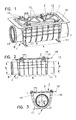
- FIG. 1 is an overall oblique view of an inventive Cleaning device
- Fig. 2 is a side view
- Fig. 3 is an end view of the same illustrate.
- FIG. 4 shows the cleaning device in longitudinal section
- FIG. 5 also provides an insert and a lid for the cleaning device Longitudinal section.
- Fig. 6 shows a modified pipe cleaning device in longitudinal section;
- Fig. 7 shows the internals of this variant with a lid.
- Fig. 8 shows a further variant in Longitudinal section and
- Fig. 9 shows the internals and the lid also in section.
- Fig. 10th is the representation of another use for the pipe cleaning device in the oblique view.
- a pipe cleaning device as it can be used in particular for a drainage channel, is of a pipe piece 1 for installation in a pipeline, i. into a drainage channel, formed, wherein the pipe section 1 a closable with a cover 2 cleaning opening. 3 having.
- a section area 4 of the pipe section 1 with provided a U-shaped cross-section, preferably, as in the sectional figures shown, has a larger inner diameter 5 than the nominal diameter 6 of the Pipe piece 1, i. its pipe connecting pieces 7, 8, which on both sides of the section area. 4 are provided with a U-shaped cross section, wherein at one end of the pipe section 1 a so-called spigot end 7 and at the opposite end a socket end 8 is provided.
- the section portion 4 of U-shaped cross-section is outside with reinforcing ribs 9, which extend around its circumference and in its longitudinal direction, provided so that even with a concreting of this pipe section 1 impressing the plane Side wall parts 10 is prevented. Likewise, a Nachau solid should thereby can be prevented when the pipe section is laid, for example, exposed. To the easier handling or laying the pipe section 1 is further arranged with end Outrigger 11 provided.
- the section area 4 with a U-shaped cross-section forms at the top one rectangular opening 3, namely the plaster opening, which is closable with the lid 2, which cover 2 is provided with stiffening ribs 12.
- Pipe piece 1 are preferably four in the pipe section 1 arranged brackets 13th screwed threaded screws 14 with handles 15.
- the upper edge of the opening 3 of the section portion 4 with U-shaped cross-section is with an outwardly extending flange 16, which provides a simple installation of the Pipe part 1 allows in a soil; such as e.g. a screed up to this flange 16 be introduced.
- section region 4 with U-shaped Cross-section oblique end surfaces 17 which diverge upwards.
- These sloping surfaces 17 form sealing surfaces for a pipe element 18 shown in FIG in the recess formed by the section area 4 of U-shaped cross-section can be used.
- This tubular element 18 also has obliquely designed end faces 19, which arrive at the inclined surfaces 17 of the pipe section 1 to the plant and thus Form counter surfaces.
- This pipe element 18 has the nominal diameter 6 of the pipe section 1, so that when it is used in the pipe section 1, a obstacle-free and vortex-free flow of Liquid, e.g. of contaminated wastewater, is given.
- the tubular element 18 has upwardly directed handles 20 which, with the lid 2 on this to the plant arrive, so that a position assurance of the tubular element 18 in the section area 4 with U-shaped Cross section is given.
- the pipe section 1 has pipe connections 7 ', 8'. with a smaller nominal diameter 6 'than those shown in Figs. 1-7 Embodiments.
- the tube member 18, which is entirely by the section region 4 extends with a U-shaped cross-section, also with such Nominal diameter 6 is formed, however, back pressure fuses 22, 22 'used are, as they are also used in the examples of FIGS. 6 and 7, so that with a Size of the backflow protection 22, 22 'for a plurality of nominal diameters 6, 6' of the pipeline the end is found.
- Fig. 10 illustrates an insert 27, as it is useful in pipe cleaning instead of Tube member 18 is inserted into the pipe section 1.
- This is open at the top, points to the End surfaces 28, 29 handles 30, and it is an end surface 29 with an opening 31 in the size of the nominal diameter 6 or 6 'and an end face 28 is provided with a Provided variety of through holes 32 and thus has a screening effect. This can be taken from this insert 27 accumulating solids in it, without this in the other, subsequent to the pipe section 1 pipe section arrives.
- an opening 33 is provided which with a plug 34, the preferably in this opening 33 can be screwed or with a bayonet connection is connectable, is closed.
- This opening 23 serves to remove the lid 2 to check if the pipeline is under pressure.
Landscapes
- Health & Medical Sciences (AREA)
- Life Sciences & Earth Sciences (AREA)
- Engineering & Computer Science (AREA)
- Hydrology & Water Resources (AREA)
- Public Health (AREA)
- Water Supply & Treatment (AREA)
- Sink And Installation For Waste Water (AREA)
- Sewage (AREA)
Abstract
Description
Claims (10)
- Rohrreinigungseinrichtung für eine flüssigkeitsführende Rohrleitung, insbesondere für einen Ablaufkanal, mit einem Rohrstück (1) zum Einbau in die Rohrleitung, welches Rohrstück (1) eine mit einem Deckel (2) verschließbare Putzöffnung (3) aufweist, wobei das Rohrstück (1) im Bereich der Putzöffnung (3) einen Abschnittsbereich (4) mit einem U-förmigen Querschnitt aufweist, in welchen Abschnittsbereich (4) eine Rückstausicherung (22, 22'), vorzugsweise zwei in Strömungsrichtung hintereinander vorzusehende Rückstausicherungen (22, 22') einsetzbar sind, dadurch gekennzeichnet, dass das Rohrstück (1) im Abschnittsbereich (4) mit U-förmigem Querschnitt einen größeren Durchmesser (5) aufweist als der Nenndurchmesser (6, 6') des Rohrstücks (1), in welchen Abschnittsbereich ein dem Nenndurchmesser (6, 6') des Rohrstücks (1) angepasstes Rohrelement (18, 18') oder stattdessen mindestens eine mindestens dem Nenndurchmesser (6, 6') des Rohrstücks (1) angepasste Rückstausicherung (22, 22') sowie gegebenenfalls ein Einsatz (27) mit einem Siebboden (28) oder ein Absperreinsatz einsetzbar ist.
- Rohrreinigungseinrichtung nach Anspruch 1, dadurch gekennzeichnet, dass der Abschnittsbereich (4) mit U-förmigem Querschnitt Platz für zwei in Strömungsrichtung der Flüssigkeit hintereinander angeordnete Rückstausicherungen (22, 22') aufweist, wobei in den Abschnittsbereich (4) mit U-förmigem Querschnitt wahlweise ein dem Nenndurchmesser (6, 6') des Rohrstücks angepasstes, und den gesamten Abschnittsbereich (4) mit U-förmigem Querschnitt überbrückendes Rohrelement (18) oder stattdessen eine mindestens dem Nenndurchmesser (6, 6') angepasste Rückstausicherung (22) sowie ein den restlichen Raum des Abschnittsbereiches mit U-förmigem Querschnitt ausfüllendes und mindestens dem Nenndurchmesser (6, 6') des Rohrstücks (1) angepasstes Rohrelement (18') oder zwei den Raum des Abschnittsbereichs (4) mit U-förmigem Querschnitt ausfüllende und mindestens dem Nenndurchmesser (6, 6') des Rohrstücks (1) angepasste Rückstausicherungen (22, 22') einsetzbar sind.
- Rohrreinigungseinrichtung nach Anspruch 1 oder 2, dadurch gekennzeichnet, dass beidenends des Abschnittbereiches (4) mit U-förmigem Querschnitt Rohranschlussstücke (7, 8, 7', 8') mit dem Nenndurchmesser (6, 6') des Rohrstücks (1), und zwar eines als Spitzende und eines als Muffenende, vorgesehen sind.
- Rohrreinigungseinrichtung nach einem oder mehreren der Ansprüche 1 bis 3,
dadurch gekennzeichnet, dass der Abschnittsbereich (4) mit U-förmigem Querschnitt an seinen längsseitigen Enden von zueinander geneigten Flächen (17), die zur Putzöffnung (3) divergieren, begrenzt ist. - Rohrreinigungseinrichtung nach einem oder mehreren der Ansprüche 1 bis 4,
dadurch gekennzeichnet, dass das Rohrelement (18, 18') und die Rückstausicherung (22, 22') jeweils an die zueinandergeneigten Flächen (17) des Rohrstücks in der Neigung angepasste Gegenflächen (19, 19', 23) aufweisen. - Rohrreinigungseinrichtung nach einem oder mehreren der Ansprüche 1 bis 5,
dadurch gekennzeichnet, dass das Rohrelement (18, 18') sowie die Rückstausicherung (22, 22') jeweils endseitig mit Dichtflächen (19, 19', 23), in die gegebenenfalls Dichtringe (21, 21') eingearbeitet sind, versehen sind. - Rohrreinigungseinrichtung nach einem oder mehreren der Ansprüche 1 bis 6,
dadurch gekennzeichnet, dass die Rückstausicherung (22, 22') mit einer Hand- (26) und/oder Motorabsperrung versehen ist. - Rohrreinigungseinrichtung nach einem oder mehreren der Ansprüche 1 bis 7,
dadurch gekennzeichnet, dass die Rückstausicherung (22, 22') mit einer elektronisch geregelten Klappe (24, 24') versehen ist. - Rohrreinigungseinrichtung nach einem oder mehreren der Ansprüche 1 bis 8,
dadurch gekennzeichnet, dass in dem Deckel (2) eine mit einem Pfropfen (34) verschließbare Druckprobeöffnung (33) vorgesehen ist. - Rohrreinigungseinrichtung nach einem oder mehreren der Ansprüche 1 bis 9,
dadurch gekennzeichnet, dass das Rohrelement (18, 18') an einer Seite mit einem zum Deckel hin ausgerichteten Handgriff (20, 20') versehen ist.
Applications Claiming Priority (2)
| Application Number | Priority Date | Filing Date | Title |
|---|---|---|---|
| AT20712003A AT412887B (de) | 2003-12-22 | 2003-12-22 | Rohrreinigungseinrichtung |
| AT20712003 | 2003-12-22 |
Publications (1)
| Publication Number | Publication Date |
|---|---|
| EP1548194A1 true EP1548194A1 (de) | 2005-06-29 |
Family
ID=33569212
Family Applications (1)
| Application Number | Title | Priority Date | Filing Date |
|---|---|---|---|
| EP04450235A Withdrawn EP1548194A1 (de) | 2003-12-22 | 2004-12-20 | Rohrreinigungseinrichtung |
Country Status (2)
| Country | Link |
|---|---|
| EP (1) | EP1548194A1 (de) |
| AT (1) | AT412887B (de) |
Cited By (3)
| Publication number | Priority date | Publication date | Assignee | Title |
|---|---|---|---|---|
| EP3026185A1 (de) * | 2014-11-11 | 2016-06-01 | ACO Severin Ahlmann GmbH & Co. KG | Rückstauverschluss |
| EP3103932A1 (de) * | 2015-06-11 | 2016-12-14 | ACO Severin Ahlmann GmbH & Co. KG | Rückstauverschluss |
| CN115193829A (zh) * | 2022-02-22 | 2022-10-18 | 舜元建设(集团)有限公司 | 一种空调管道循环冲洗系统 |
Citations (4)
| Publication number | Priority date | Publication date | Assignee | Title |
|---|---|---|---|---|
| EP0047482A2 (de) * | 1980-09-04 | 1982-03-17 | Firma Helmuth Dallmer | Abwasserrohr mit Reinigungsöffnung und wegnehmbarer Rückstauklappe |
| DE3306968A1 (de) * | 1983-02-28 | 1984-08-30 | Passavant-Werke AG & Co KG, 6209 Aarbergen | Rueckstauverschluss fuer entwaesserungsleitungen |
| DE8702300U1 (de) * | 1987-02-14 | 1988-06-23 | Fa. Franz Viegener Ii, 5952 Attendorn, De | |
| EP0926301A2 (de) * | 1997-12-23 | 1999-06-30 | Bernhard Kessel | Rückstauverschlussvorrichtung |
Family Cites Families (3)
| Publication number | Priority date | Publication date | Assignee | Title |
|---|---|---|---|---|
| DE3127487C2 (de) * | 1981-07-11 | 1989-07-20 | Bernhard 8071 Lenting Kessel | Reinigungsrohr |
| DE3331082A1 (de) * | 1983-08-29 | 1985-03-14 | Passavant-Werke AG & Co KG, 6209 Aarbergen | Reinigungsrohr mit rueckstauverschluss |
| DE3731160A1 (de) * | 1987-09-17 | 1989-03-30 | Bernhard Kessel | Verwendung eines reinigungsrohres fuer durchgehende abwasser-rohrleitungen als rueckflussverhinderer fuer jegliche abwaesserarten |
-
2003
- 2003-12-22 AT AT20712003A patent/AT412887B/de not_active IP Right Cessation
-
2004
- 2004-12-20 EP EP04450235A patent/EP1548194A1/de not_active Withdrawn
Patent Citations (4)
| Publication number | Priority date | Publication date | Assignee | Title |
|---|---|---|---|---|
| EP0047482A2 (de) * | 1980-09-04 | 1982-03-17 | Firma Helmuth Dallmer | Abwasserrohr mit Reinigungsöffnung und wegnehmbarer Rückstauklappe |
| DE3306968A1 (de) * | 1983-02-28 | 1984-08-30 | Passavant-Werke AG & Co KG, 6209 Aarbergen | Rueckstauverschluss fuer entwaesserungsleitungen |
| DE8702300U1 (de) * | 1987-02-14 | 1988-06-23 | Fa. Franz Viegener Ii, 5952 Attendorn, De | |
| EP0926301A2 (de) * | 1997-12-23 | 1999-06-30 | Bernhard Kessel | Rückstauverschlussvorrichtung |
Cited By (4)
| Publication number | Priority date | Publication date | Assignee | Title |
|---|---|---|---|---|
| EP3026185A1 (de) * | 2014-11-11 | 2016-06-01 | ACO Severin Ahlmann GmbH & Co. KG | Rückstauverschluss |
| EP3103932A1 (de) * | 2015-06-11 | 2016-12-14 | ACO Severin Ahlmann GmbH & Co. KG | Rückstauverschluss |
| CN115193829A (zh) * | 2022-02-22 | 2022-10-18 | 舜元建设(集团)有限公司 | 一种空调管道循环冲洗系统 |
| CN115193829B (zh) * | 2022-02-22 | 2023-07-25 | 舜元建设(集团)有限公司 | 一种空调管道循环冲洗系统 |
Also Published As
| Publication number | Publication date |
|---|---|
| ATA20712003A (de) | 2005-01-15 |
| AT412887B (de) | 2005-08-25 |
Similar Documents
| Publication | Publication Date | Title |
|---|---|---|
| AT508270B1 (de) | Siphon | |
| EP1679407A1 (de) | Rückstauverschluss | |
| DE102012001610B4 (de) | Rohreinbausatz | |
| DE2203370A1 (de) | Vorrichtung zum verankern von rohrleitungsaustritten in der wand | |
| DE202016000056U1 (de) | Ventilarmatur für die Befüllung eines sanitären Spülkastens und sanitärer Spülkasten mit einer solchen Ventilarmatur | |
| DE102005016526B3 (de) | Absperrvorrichtung für einen Abwasserkontrollschacht | |
| AT412887B (de) | Rohrreinigungseinrichtung | |
| DE3504127A1 (de) | Anschlusseinrichtung fuer armaturen | |
| DE102009009707B4 (de) | Entwässerungsvorrichtung | |
| EP3020878B1 (de) | Hydrant mit kontrollrohr | |
| EP3686366B1 (de) | Abflussleitungsanordnung | |
| EP2636812A1 (de) | Verfahren und Vorrichtung zur Dachentwässerung in Form einer Hauptentwässerung und einer Notentwässerung | |
| EP3795759A2 (de) | Schutzrohrsystem | |
| AT413237B (de) | Absperrschieber für druckrohrleitungen | |
| DE102010016647B4 (de) | Bodenablauf und Geruchsverschlusselement für einen Bodenablauf | |
| EP1347221B1 (de) | Absperrschieber mit Auflagedichtung | |
| DE202007008019U1 (de) | Entwässerungssystem | |
| DE2848498A1 (de) | Inspektionskammer-anordnung | |
| DE102004061168A1 (de) | Einbaugarnitur | |
| DE10240906B4 (de) | Kanalschacht für Abwasser-Kanalisation | |
| DE102007010774B4 (de) | Anordnung mit einem vertikalen zylindrischen Ablaufrohr | |
| DE2609374A1 (de) | Einsteckteil | |
| DE202015107000U1 (de) | Ablaufsystem | |
| DE202021106521U1 (de) | Mobiles Hochwasserschutzsystem | |
| DE2647273A1 (de) | Wasserablaufkasten mit absperrvorrichtung |
Legal Events
| Date | Code | Title | Description |
|---|---|---|---|
| PUAI | Public reference made under article 153(3) epc to a published international application that has entered the european phase |
Free format text: ORIGINAL CODE: 0009012 |
|
| AK | Designated contracting states |
Kind code of ref document: A1 Designated state(s): AT BE BG CH CY CZ DE DK EE ES FI FR GB GR HU IE IS IT LI LT LU MC NL PL PT RO SE SI SK TR |
|
| AX | Request for extension of the european patent |
Extension state: AL BA HR LV MK YU |
|
| 17P | Request for examination filed |
Effective date: 20051216 |
|
| AKX | Designation fees paid |
Designated state(s): AT BE BG CH CY CZ DE DK EE ES FI FR GB GR HU IE IS IT LI LT LU MC NL PL PT RO SE SI SK TR |
|
| AXX | Extension fees paid |
Extension state: YU Payment date: 20051216 Extension state: MK Payment date: 20051216 Extension state: HR Payment date: 20051216 Extension state: BA Payment date: 20051216 Extension state: AL Payment date: 20051216 |
|
| STAA | Information on the status of an ep patent application or granted ep patent |
Free format text: STATUS: THE APPLICATION IS DEEMED TO BE WITHDRAWN |
|
| 18D | Application deemed to be withdrawn |
Effective date: 20110701 |