EP1548178A2 - Wäschetrockner und Kondensator dafür - Google Patents
Wäschetrockner und Kondensator dafür Download PDFInfo
- Publication number
- EP1548178A2 EP1548178A2 EP04293098A EP04293098A EP1548178A2 EP 1548178 A2 EP1548178 A2 EP 1548178A2 EP 04293098 A EP04293098 A EP 04293098A EP 04293098 A EP04293098 A EP 04293098A EP 1548178 A2 EP1548178 A2 EP 1548178A2
- Authority
- EP
- European Patent Office
- Prior art keywords
- condenser
- laundry dryer
- dryer according
- receiving unit
- insertion member
- Prior art date
- Legal status (The legal status is an assumption and is not a legal conclusion. Google has not performed a legal analysis and makes no representation as to the accuracy of the status listed.)
- Withdrawn
Links
Images


Classifications
-
- D—TEXTILES; PAPER
- D06—TREATMENT OF TEXTILES OR THE LIKE; LAUNDERING; FLEXIBLE MATERIALS NOT OTHERWISE PROVIDED FOR
- D06F—LAUNDERING, DRYING, IRONING, PRESSING OR FOLDING TEXTILE ARTICLES
- D06F58/00—Domestic laundry dryers
- D06F58/20—General details of domestic laundry dryers
- D06F58/24—Condensing arrangements
Definitions
- the present invention relates to a laundry dryer, and more particularly, to a laundry dryer having a condenser assembly that is designed to prevent high temperature/moisture circulating air passing through a condenser and/or low temperature interior air introduced by a cooling fan from leaking through a gap formed on a front and/or rear sides of the condenser.
- a drum-type laundry dryer is designed to perform the drying operation while rotating laundry loaded in a dry drum.
- the laundry rotates and drops by the rotation of the laundry drum.
- High-temperature dry air introduced into the dry drum is mixed with the laundry to vaporize the moisture soaked in the laundry.
- the laundry dryer may be classified into a condenser-type dryer and an exhaust-type dryer.
- the former is designed such that the air in the dry drum is directed to a condenser and a heater and is then returned to the dry drum. That is, the air circulates in the dryer without being exhausted out of the dryer.
- the latter is designed such that the air in the dry drum is directed to the condenser so that the moisture contained in the air can be eliminated and is then exhausted out of the dryer.
- the air circulating in the dryer absorbs the moisture from the laundry loaded in the drum and passes through the condenser to be lowered in its temperature by a heat-exchange. As the temperature of the air is lowered, the moisture contained in the air is condensed. The condensed water is pumped out by a condensing pump and is then exhausted to an exterior side.
- the condenser functioning to condense interior air formed into high temperature/moisture state while passing through an inside of the drum should be designed to maintain a perfect seal when it is assembled in a condenser receiving unit.
- the condensed water generated when the air in the drum passes through the condenser cannot be transferred to the sump but leaked out of the dryer.
- the moisture contained in the circulating air that is leaked out of the condenser may be condensed on a surface of a base in which the condensed water is received.
- the present invention is directed to a condenser assembly of a laundry dryer that substantially obviates one or more problems due to limitations and disadvantages of the related art.
- An object of the present invention is to provide a condenser assembly of a laundry dryer that can provide a perfect seal when a condenser is assembled in the laundry dryer.
- Another object of the present invention is to provide a condenser assembly of a laundry dryer that has a handle making it easy to insert and remove a condenser into or from the laundry dryer.
- Another object of the present invention is to provide a condenser assembly of a laundry dryer that allows a condenser to be smoothly inserted into a laundry dryer.
- a laundry dryer comprising: a base; a condenser receiving unit formed in the base; and a condenser inserted in the condenser receiving unit and provided with an insertion member.
- a laundry dryer comprising: a condenser; a handle ring formed on a front portion of the condenser; an insertion member rotatably mounted on the front portion of the condenser; a base having a concave portion for receiving the condenser, the base being provided at a concave portion with a groove in which the insertion member is coupled; and a sealing surface elevated from the concave portion by a predetermined height.
- a laundry dryer comprising: a dry drum; a condenser in which circulating air passing through the dry drum is introduced and heat-exchanged with interior air; a base having a receiving unit for receiving the condenser; an insertion member mounted on front both sides of the condenser to allow the condenser to tightly contact the receiving unit; and a guide rib formed in the receiving unit to allow the condenser to be smoothly inserted.
- the condenser can be assembled in the dryer with the perfect seal, the leakage of the condensed water generated on the condenser out of the dryer can be prevented.
- the condenser when the condenser is inserted into the dryer, the condenser can be smoothly inserted.
- Fig. 1 is a sectional view of a condenser-type laundry dryer with a condenser assembly according to an embodiment of the present invention
- Fig. 2 is a perspective view of a base in which a condenser is inserted according to an embodiment of the present invention
- Fig. 3 is a front perspective view of a condenser according to an embodiment of the present invention.
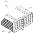
- Fig. 4 is a rear perspective view of a condenser depicted in Fig. 3;
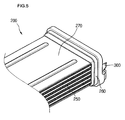
- Fig. 5 is a side perspective view of a condenser depicted in Fig. 3;
- Fig. 6 is an enlarged perspective view of a condenser insertion member according to an embodiment of the present invention.
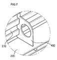
- Fig. 7 is an enlarged perspective view of a handle ring provided on a condenser according to an embodiment of the present invention.
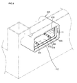
- Fig. 8 is a partial perspective view of a condenser receiving unit according to a first embodiment of the present invention.
- Fig. 9 is a partial perspective view of a condenser receiving unit according to a second embodiment of the present invention.
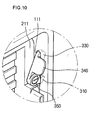
- Fig. 10 is an enlarged view of a state where a condenser is forcedly fitted by an insertion member according to an embodiment of the present invention.
- Fig. 1 is a sectional view of a condenser-type laundry dryer with a condenser assembly according to an embodiment of the present invention.
- a condenser-type laundry dryer 30 includes an outer case 10, a cylindrical drum 12 mounted in the outer case 10 to receive the laundry therein, a door 13 controlling the opening of the drum 12, and a belt 11 disposed around an outer circumference of the drum 12 to rotate the drum 12.
- the condenser-type laundry dryer 30 further includes a motor shaft 21 connected to the belt 11 to transmit rotational force to the drum 12, a motor 17 for transmitting the rotational force to the motor shaft 21, and a cooling fan 16 connected to a first end of the motor shaft 21 to rotate by receiving the rotational force of the motor 17 and intake interior air.
- the laundry dryer 30 further includes a dry fan 18 connected to a second end of the motor shaft 15 to circulate air in the drum 12, a duct cover 20 connecting the dry fan 18 to the drum 12 to allow the air introduced by the dry fan 18 to be directed to the drum 12, and a base 100 for mounting the motor 17 and receiving the cooling fan 16 and a dry fan 18.
- the cooling fan 16 and the dry fan 18 are disposed facing each other and the motor 17 is disposed between the cooling and dry fans 16 and 18.
- the dry fan 18 and the heater 19 are received in the duct cover 20 defining an air passage through which the circulating air introduced by the dry fan 10 is directed reward of the drum 12.
- the dryer 30 is formed on a rear surface of the door 13, including a door lint filter 13a for primarily filtering foreign objects contained in the circulating air and a body lint filter 14 for secondary filtering foreign objects contained in the circulating air passing through the door lint filter 13a.
- a circulation duct 15 along which the circulating air passing through the body lint duct 14 is directed to a condenser (not shown).
- the motor 17 When electric power is applied to the dryer 30, the motor 17 is operated and the heater 19 mounted in the duct cover 20 is heated. Then, the belt 11 connected to the motor shaft 21 rotates to rotate the drum 12. As the drum 12 rotates, the laundry in the drum 12 is lifted and dropt by a lift (not shown) mounted on the inner wall of the drum 12.
- the dry fan 18 connected to the motor shaft 21 rotates by the rotation of the motor 17 to introduce the circulating air via the condenser 200.
- the air flows upward along the duct cover 20 and passes through the heater 19 to be converted into high-temperature/dry air. Then, the air is directed into the drum to absorb the moisture contained in the laundry, thereby being converted into the high-temperature/damp air.
- the high-temperature/damp air is directed to the condenser 200 along the circulation duct 15 via the door lint filter 13a and the body lint filter 14.
- the high-temperature/damp air gives heat to the interior air as it goes through the condenser 200, thereby being changed into low-temperature/damp air, in the coursed of which the moisture contained in the low-temperature/damp air is condensed.
- the condensed moisture is dropt on the surface of the condenser 200 and is then directed to a sump (150 in Fig. 2).
- the moisture directed to the sump 150 is transmitted to a drawer 23 disposed on an upper portion of the dryer 300. Meanwhile, the interior air passing trough the condenser 200 takes the heat from the high-temperature/damp air to change the circulating air into the low-temperature/damp air. As a result, the temperature of the interior air is increased.
- the circulating air introduced by the dry fan 18 flows along the passage defined by the duct cover 20. Then, as it passes through the heater 19, it is changed into the high-temperature/dry air and is then directed into the drum 12.
- the circulating air circulates in the order of the drum, the lint filters, the condenser and the duct cover.
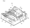
- Fig. 2 is a perspective view of the base in which the condenser according to an embodiment of the present invention is inserted.
- the base 100 for receiving the condenser 200 includes a circulating air descending part 110 by which the interior air passing through the door lint filter 13a via the drum 12 is descended, a condenser insertion opening 112 in which the condenser 200 is inserted rearward, and a circulating air passage 170 extending from a rear end of the condenser 200 to guide the flow of the air passing through the condenser 200.
- the base 100 further includes an interior air intake hole 120 spaced away from the condenser insertion opening 112 to intake the interior air and a cooling fan seating groove 130 on which the cooling fan 16 for introducing the interior air is seated.
- the motor 17 is seated on a rear side of the cooling fan seating groove 130 and a heat discharge groove 140 for discharging the heat generated from the motor 17 is also formed on the rear side of the cooling fan seating groove 130.
- the sump 150 is provided on a center of the base 100 to accumulate the condensed water generated by the condenser 200 therein.
- the fluid circulation in the base 100 will be briefly described hereinafter.
- the circulating air changed into the high temperature/damp state as it passes through the drum passes through the door and body lint filters 13a and 14a.
- the interior air introduced through the interior air intake hole 120 is directed to the condenser 200 via the cooling fan 16.
- the condenser 200 is designed such that the circulating air and the interior air cross each other therein.
- the circulating air passing through the condenser 200 is directed to the dry duct 20 provided on a rear wall of the dryer along the circulating air passage 170 is then exhausted to the interior side.
- Figs. 3 through 5 show the condenser according to an embodiment of the present invention.
- the inventive condenser 200 includes a main body 270, a front frame formed on an edge of a front portion of the main body 270, a circulation air intake hole 210 formed in the front frame 211, a condenser handle ring 400 formed on a front center of the condenser 200, a condenser insertion member 300 formed on both sides of the front frame 211 to forcedly insert the condenser 200, and a front sealing seat 220 further extending frontward than the front frame 211.
- a front sealing member 260 is formed on a rear surface of the front frame 211 to maintain a seal state when the condenser is assembled.
- a circulating air exhaust hole 230 for exhausting the interior air introduced through the circulating air intake hole 210 is further provided.
- the condenser 200 is provided at a side portion with interior air intake and exhaust holes 251 and 250 for introducing and exhausting the interior air introduced by the cooling fan 16.
- the circulation air intake and exhaust holes 210 and 230 and the interior air intake and exhaust holes 251 and 250 are disposed at a different layer to intersect each other so that the circulating air and the interior air are not mixed with each other but heat-exchanged with each other.
- Fig. 6 shows an enlarged perspective view of the condenser insertion member according to an embodiment of the present invention
- Fig. 7 shows an enlarged perspective view of the handle ring provided on the condenser according to an embodiment of the present invention.
- the condenser insertion member 300 is mounted on the both sides of the front frame 211 defining the front edge of the condenser 200.
- the insertion member 300 includes a rotational center shaft 350 that is coupled to the front frame 211.
- the rotational shaft 350 is preferably formed in a screw-shape so that the rotational shaft 350 can be screw-coupled to the front frame 211.
- the insertion member 300 is designed to rotate by a predetermined angle around the rotational shaft 350.
- the insertion member 300 further includes a rotational lever 330 extending at a predetermined length and an insertion projection 310 extending from an end portion of the rotational lever 330.
- the insertion projection 310 formed on an outer circumference of the insertion member 300 has a predetermined thickness and an inclined insertion surface 320 is formed on an extreme end of the insertion projection 310 so that a width of the insertion projection 310 is reduced as it goes toward the extreme end.
- the insertion projection 310 when the insertion projection 310 is inserted in an insertion hole 111 formed on a side surface of a condenser receiving unit (see Fig. 8), the insertion projection 310 can be smoothly inserted in the insertion hole 111 by the inclined insertion surface 320.
- the condenser handle ring 400 is formed on the front surface of the condenser so that the user can insert a his/her finger into the ring 400.
- the handle ring 400 plays a roll of this function.
- the condenser handle ring 400 is vertically formed on the front seal seat 220 provided on a front lower portion of the condenser and the handle ring 400 defines a hole having a predetermined diameter.
- the forming location of shape of the handle ring is not limited to the above. A variety of other structures that can provide the convenience for the user to grasp the condenser will be possible.
- Fig. 8 shows a partial perspective view of the condenser receiving unit according to a first embodiment of the present invention
- Fig. 9 shows a partial perspective view of the condenser receiving unit according to a second embodiment of the present invention.
- the condenser receiving unit 600 includes the condenser insertion opening 112 formed on the front surface of the base 100 to receive the condenser 200, a front sealing flange 620 disposed around an inner circumference of a portion located at a predetermined depth from the condenser insertion opening 112, and an insertion hole 11 formed on one of the both sides of the condenser receiving unit 600 to receive the insertion projection 310.
- the condenser receiving unit 600 includes an interior air intake hole 630 through which the interior air is introduced by the cooling fan 16.
- the interior air intake hole 630 is formed on a side of the condenser receiving unit 600.
- the front sealing flange 620 contacts the front sealing member 260 provided on a rear surface of the front frame 211 of the condenser 200 so as to prevent the circulating and interior airs introduced into the condenser 200 from being leaked through the front portion of the base 100.
- the condenser 200 according to the present invention inserted in the condenser receiving unit 600 provided on an edge of the base 100 of the dryer 30.
- the condenser receiving unit 600 has an identical shape to that of the front portion of the condenser.
- a guide rail 500 is formed on a bottom 610 of the condenser receiving unit 600, extending in a longitudinal direction with a predetermined height.
- At least one supporting rib 510 supporting the guide rail 500 may be formed on one of the both sides of the guide rail 500.
- the height, length and number of the guide rail 500 provided on the bottom 610 of the condenser receiving unit are not limited to this embodiment.
- the condenser 200 is first inserted into the condenser receiving unit 600.
- the bottom of the insertion projection 310 is located on the insertion hole 11.
- the insertion projection 310 is inserted into the insertion hole 11 along the inclined insertion surface 320.
- the condenser 200 is forcedly inserted by a thickness corresponding to a thickness of the insertion projection 310. Accordingly, the sealing member provided on the front surface of the condenser 200 tightly contacts the front sealing surface 620 formed on the condenser receiving unit 600, thereby providing a sight seal.
- the rear sealing member 240 provided on a rear edge of the condenser 200 tightly contacts the sealing surface formed on the rear surface of the condenser receiving unit 600.
Landscapes
- Engineering & Computer Science (AREA)
- Textile Engineering (AREA)
- Detail Structures Of Washing Machines And Dryers (AREA)
Applications Claiming Priority (6)
| Application Number | Priority Date | Filing Date | Title |
|---|---|---|---|
| KR2003094465 | 2003-12-22 | ||
| KR1020030094466A KR100607268B1 (ko) | 2003-12-22 | 2003-12-22 | 건조기의 컨덴서 조립구조 |
| KR1020030094465A KR100607267B1 (ko) | 2003-12-22 | 2003-12-22 | 건조기의 컨덴서 조립구조 |
| KR2003094468 | 2003-12-22 | ||
| KR1020030094468A KR100607269B1 (ko) | 2003-12-22 | 2003-12-22 | 건조기의 컨덴서 조립구조 |
| KR2003094466 | 2003-12-22 |
Publications (2)
| Publication Number | Publication Date |
|---|---|
| EP1548178A2 true EP1548178A2 (de) | 2005-06-29 |
| EP1548178A3 EP1548178A3 (de) | 2011-10-19 |
Family
ID=34557062
Family Applications (1)
| Application Number | Title | Priority Date | Filing Date |
|---|---|---|---|
| EP04293098A Withdrawn EP1548178A3 (de) | 2003-12-22 | 2004-12-22 | Wäschetrockner und Kondensator dafür |
Country Status (5)
| Country | Link |
|---|---|
| US (1) | US7036243B2 (de) |
| EP (1) | EP1548178A3 (de) |
| JP (1) | JP4476115B2 (de) |
| CN (1) | CN100408750C (de) |
| AU (1) | AU2004242448B2 (de) |
Cited By (14)
| Publication number | Priority date | Publication date | Assignee | Title |
|---|---|---|---|---|
| WO2006097369A1 (de) * | 2005-03-18 | 2006-09-21 | BSH Bosch und Siemens Hausgeräte GmbH | Kondensations-wäschetrockner |
| WO2007074124A1 (en) | 2005-12-29 | 2007-07-05 | Arcelik Anonim Sirketi | A dryer |
| WO2007077093A1 (en) * | 2005-12-30 | 2007-07-12 | Arcelik Anonim Sirketi | A dryer |
| WO2007090701A1 (de) * | 2006-02-08 | 2007-08-16 | BSH Bosch und Siemens Hausgeräte GmbH | Wäschetrockner mit einer bodengruppe |
| WO2007090708A1 (de) * | 2006-02-08 | 2007-08-16 | BSH Bosch und Siemens Hausgeräte GmbH | Kondensatorgehäuse mit mindestens einer dünnen wand und dieses kondensatorgehäuse enthaltender kondensationstrockner |
| EP2196578A1 (de) | 2008-12-11 | 2010-06-16 | Electrolux Home Products Corporation N.V. | Wäschetrockner mit abnehmbarem Kondensator |
| CN101251342B (zh) * | 2007-02-23 | 2011-05-25 | Lg电子株式会社 | 热交换器及具有该热交换器的冷凝型干衣机 |
| US8056254B2 (en) | 2005-07-29 | 2011-11-15 | Bsh Bosch Und Siemens Hausgeraete Gmbh | Tumble dryer with a lint filter |
| EP2423375A1 (de) * | 2010-08-24 | 2012-02-29 | Electrolux Home Products Corporation N.V. | Waschmaschine mit Drehtrommel |
| EP2423378A1 (de) * | 2010-08-25 | 2012-02-29 | Electrolux Home Products Corporation N.V. | Wäschebehandlungsmaschine |
| WO2012062894A2 (en) | 2010-11-12 | 2012-05-18 | Arcelik Anonim Sirketi | A dryer comprising a removable piece |
| WO2014117829A1 (en) * | 2013-01-30 | 2014-08-07 | Arcelik Anonim Sirketi | Clothes dryer condenser unit locking mechanism |
| US8844163B2 (en) | 2010-08-25 | 2014-09-30 | Electrolux Home Products Corporation N.V. | Laundry treating machine with basement portion providing airflow paths |
| EP3849316B1 (de) | 2018-09-14 | 2024-05-15 | MIWE Michael Wenz GmbH | Gargerät mit schwadenkondensator |
Families Citing this family (41)
| Publication number | Priority date | Publication date | Assignee | Title |
|---|---|---|---|---|
| US7628043B2 (en) | 2000-07-25 | 2009-12-08 | Whirlpool Corporation | Modular laundry system with horizontal modules |
| US20070266740A9 (en) | 2000-07-25 | 2007-11-22 | Kendall James W | Vertical laundry module |
| US7624600B2 (en) | 2000-07-25 | 2009-12-01 | Whirlpool Corporation | Modular laundry system with horizontally arranged cabinet module |
| US7617702B2 (en) | 2000-07-25 | 2009-11-17 | Whirlpool Corporation | Modular laundry system with cabinet module |
| KR100556503B1 (ko) * | 2002-11-26 | 2006-03-03 | 엘지전자 주식회사 | 건조기의 건조 시간제어 방법 |
| US7627960B2 (en) * | 2003-06-30 | 2009-12-08 | General Electric Company | Clothes dryer drum projections |
| KR101093878B1 (ko) * | 2004-06-05 | 2011-12-13 | 엘지전자 주식회사 | 건조기의 드럼 장치 |
| KR101093988B1 (ko) * | 2004-06-05 | 2011-12-15 | 엘지전자 주식회사 | 건조기의 도어 린트 필터 밀착 장치 |
| US20070151306A1 (en) | 2005-12-30 | 2007-07-05 | Gilboe Kevin J | Modular laundry system with work surface |
| US20070151300A1 (en) | 2005-12-30 | 2007-07-05 | Sunshine Richard A | Modular laundry system with horizontal module spanning two laundry appliances |
| US20070151303A1 (en) | 2005-12-30 | 2007-07-05 | Doyle Colleen M | Modular laundry system with work surface having a functional element |
| US11255040B2 (en) | 2004-10-22 | 2022-02-22 | Whirlpool Corporation | Modular laundry system |
| US20070151304A1 (en) | 2005-12-30 | 2007-07-05 | Kendall James W | Modular laundry system with work surface having a functional insert |
| US20060117810A1 (en) | 2004-10-22 | 2006-06-08 | Kendall James W | Modular Laundry system with segmented work surface |
| KR100697070B1 (ko) * | 2004-11-06 | 2007-03-20 | 엘지전자 주식회사 | 건조기와 세탁건조기와 그 제어 방법 |
| WO2006062262A1 (en) * | 2004-12-06 | 2006-06-15 | Lg Electronics Inc. | Clothes dryer |
| KR100595763B1 (ko) * | 2004-12-07 | 2006-06-30 | 엘지전자 주식회사 | 제습 겸용 의류 건조기 |
| DE102005013049A1 (de) * | 2005-03-18 | 2006-09-21 | BSH Bosch und Siemens Hausgeräte GmbH | Kondensations-Wäschetrockner |
| DE102006002713A1 (de) * | 2005-03-18 | 2006-10-12 | BSH Bosch und Siemens Hausgeräte GmbH | Frontbaugruppe für eine Wäschetrockenmaschine |
| US8104192B2 (en) * | 2005-03-31 | 2012-01-31 | Lg Electronics Inc. | Laundry dryer |
| DE102005013053A1 (de) * | 2005-05-23 | 2006-11-30 | BSH Bosch und Siemens Hausgeräte GmbH | Kondensations-Wäschetrockner |
| US7913419B2 (en) * | 2005-12-30 | 2011-03-29 | Whirlpool Corporation | Non-tumble clothes dryer |
| US7886458B2 (en) * | 2006-12-22 | 2011-02-15 | G.A. Braun Inc. | Lint collection apparatus and system for fabric dryers |
| DE102007049959A1 (de) * | 2007-10-18 | 2009-04-23 | BSH Bosch und Siemens Hausgeräte GmbH | Flusenfiltervorrichtung und Hausgerät mit einer derartigen Flusenfiltervorrichtung |
| KR101256145B1 (ko) * | 2007-11-05 | 2013-04-23 | 동부대우전자 주식회사 | 히터 내장형 흡기관을 구비하는 건조기 |
| KR101308510B1 (ko) * | 2007-11-05 | 2013-09-12 | 동부대우전자 주식회사 | 히터 내장형 흡기관을 구비하는 건조기 |
| KR101608760B1 (ko) | 2008-04-30 | 2016-04-04 | 엘지전자 주식회사 | 의류처리장치 |
| EP2113596B1 (de) * | 2008-04-30 | 2011-11-16 | LG Electronics Inc. | Waschmaschine |
| EP2113595B1 (de) * | 2008-04-30 | 2011-11-16 | LG Electronics Inc. | Waschmaschine |
| DE102009047155A1 (de) * | 2009-11-26 | 2011-06-01 | BSH Bosch und Siemens Hausgeräte GmbH | Kondensatsammelbehälter für ein Wäschetrocknungsgerät und Wäschetrocknungsgerät mit einem Kondensatsammelbehälter |
| KR20110132151A (ko) * | 2010-06-01 | 2011-12-07 | 삼성전자주식회사 | 건조기 및 건조도 측정 방법 |
| TR201011270A1 (tr) * | 2010-12-31 | 2012-07-23 | Arçeli̇k Anoni̇m Şi̇rketi̇ | Bir yıkayıcı/kurutucu. |
| KR101949356B1 (ko) * | 2012-09-21 | 2019-02-18 | 엘지전자 주식회사 | 세탁물 처리기기 |
| DE102015111452A1 (de) * | 2015-07-15 | 2017-01-19 | Miele & Cie. Kg | Wäschetrockner |
| DE102015111436A1 (de) * | 2015-07-15 | 2017-01-19 | Miele & Cie. Kg | Wäschetrockner |
| CN105986395A (zh) * | 2016-06-30 | 2016-10-05 | 赖保思 | 洗涤干燥一体机 |
| CN109234996B (zh) * | 2017-07-10 | 2021-11-30 | 青岛胶南海尔洗衣机有限公司 | 一种冷凝器连接件 |
| US10604882B2 (en) | 2017-07-21 | 2020-03-31 | Whirlpool Corporation | Drain system for a laundry appliance |
| CN109402983B (zh) * | 2017-08-17 | 2022-04-12 | 青岛海尔洗涤电器有限公司 | 一种干衣机 |
| CN109487509B (zh) * | 2017-09-13 | 2021-07-16 | 青岛海尔洗涤电器有限公司 | 一种衣物处理设备 |
| KR20220011903A (ko) | 2020-07-22 | 2022-02-03 | 삼성전자주식회사 | 식기 세척기 |
Family Cites Families (12)
| Publication number | Priority date | Publication date | Assignee | Title |
|---|---|---|---|---|
| US2752694A (en) * | 1953-06-15 | 1956-07-03 | Gen Motors Corp | Domestic appliance |
| US3220229A (en) * | 1963-12-13 | 1965-11-30 | Gen Motors Corp | Clothes washer and dryer |
| US3538641A (en) * | 1968-06-14 | 1970-11-10 | Whirlpool Co | Two-way dryer door |
| US4023304A (en) * | 1976-06-16 | 1977-05-17 | Alex Singer | Portable compartmented lure-holding tackle box |
| US4103433A (en) * | 1976-11-08 | 1978-08-01 | Q-Dot Corporation | Home laundry dryer |
| DE3311077A1 (de) * | 1983-03-26 | 1984-10-04 | Licentia Patent-Verwaltungs-Gmbh, 6000 Frankfurt | Elektrischer waeschetrockner |
| WO1990008851A1 (de) * | 1989-02-03 | 1990-08-09 | Zanker Gmbh & Co. Ohg | Wäschetrockner |
| DE3939855A1 (de) * | 1989-12-01 | 1991-06-06 | Bosch Siemens Hausgeraete | Luftgekuehlter kondensator fuer einen haushalt-waeschetrockner |
| DE4032904A1 (de) * | 1990-10-17 | 1992-04-23 | Zanker Gmbh | Waeschetrockner |
| DE4135845A1 (de) * | 1991-10-31 | 1993-05-06 | Bauknecht Hausgeraete Gmbh, 7000 Stuttgart, De | Waeschetrockner |
| DE4436673B4 (de) * | 1994-10-13 | 2007-02-08 | BSH Bosch und Siemens Hausgeräte GmbH | Automatische, zum Trocknen eingerichtete Waschmaschine |
| CN2357034Y (zh) * | 1998-11-06 | 2000-01-05 | 中山威力集团公司 | 内循环环保型干衣机 |
-
2004
- 2004-12-21 US US11/016,710 patent/US7036243B2/en not_active Expired - Fee Related
- 2004-12-22 AU AU2004242448A patent/AU2004242448B2/en not_active Ceased
- 2004-12-22 CN CNB2004101049914A patent/CN100408750C/zh not_active Expired - Fee Related
- 2004-12-22 JP JP2004371837A patent/JP4476115B2/ja not_active Expired - Fee Related
- 2004-12-22 EP EP04293098A patent/EP1548178A3/de not_active Withdrawn
Non-Patent Citations (1)
| Title |
|---|
| MIELE: "Gebrauchsanweisung Kondenstrockner T 277 C", 13 July 2003 (2003-07-13), Internet citation, pages 1 - 48, XP055348236, Retrieved from the Internet <URL:http://www.miele.de/de/haushalt/service/ks/gebrauchsanweisungen.aspx> [retrieved on 20170221] * |
Cited By (19)
| Publication number | Priority date | Publication date | Assignee | Title |
|---|---|---|---|---|
| US7926202B2 (en) | 2005-03-18 | 2011-04-19 | Bsh Bosch Und Siemens Hausgeraete Gmbh | Condenser tumble-dryer |
| WO2006097369A1 (de) * | 2005-03-18 | 2006-09-21 | BSH Bosch und Siemens Hausgeräte GmbH | Kondensations-wäschetrockner |
| EP1920102B2 (de) † | 2005-07-29 | 2017-01-11 | BSH Hausgeräte GmbH | Wäschetrockner mit einem flusenfilter |
| US8056254B2 (en) | 2005-07-29 | 2011-11-15 | Bsh Bosch Und Siemens Hausgeraete Gmbh | Tumble dryer with a lint filter |
| WO2007074124A1 (en) | 2005-12-29 | 2007-07-05 | Arcelik Anonim Sirketi | A dryer |
| WO2007077093A1 (en) * | 2005-12-30 | 2007-07-12 | Arcelik Anonim Sirketi | A dryer |
| WO2007090708A1 (de) * | 2006-02-08 | 2007-08-16 | BSH Bosch und Siemens Hausgeräte GmbH | Kondensatorgehäuse mit mindestens einer dünnen wand und dieses kondensatorgehäuse enthaltender kondensationstrockner |
| WO2007090701A1 (de) * | 2006-02-08 | 2007-08-16 | BSH Bosch und Siemens Hausgeräte GmbH | Wäschetrockner mit einer bodengruppe |
| CN101251342B (zh) * | 2007-02-23 | 2011-05-25 | Lg电子株式会社 | 热交换器及具有该热交换器的冷凝型干衣机 |
| US8453720B2 (en) | 2007-02-23 | 2013-06-04 | Lg Electronics Inc. | Heat exchanger and condensing type laundry dryer having the same |
| EP2196578A1 (de) | 2008-12-11 | 2010-06-16 | Electrolux Home Products Corporation N.V. | Wäschetrockner mit abnehmbarem Kondensator |
| EP2423375A1 (de) * | 2010-08-24 | 2012-02-29 | Electrolux Home Products Corporation N.V. | Waschmaschine mit Drehtrommel |
| EP2423378A1 (de) * | 2010-08-25 | 2012-02-29 | Electrolux Home Products Corporation N.V. | Wäschebehandlungsmaschine |
| US8707581B2 (en) | 2010-08-25 | 2014-04-29 | Electrolux Home Products Corporation N.V. | Laundry treating machine with basement portion having multi-level air flow path |
| US8844163B2 (en) | 2010-08-25 | 2014-09-30 | Electrolux Home Products Corporation N.V. | Laundry treating machine with basement portion providing airflow paths |
| US9534843B2 (en) | 2010-08-25 | 2017-01-03 | Electrolux Home Products Corporation N.V. | Laundry treating machine with basement portion providing airflow paths |
| WO2012062894A2 (en) | 2010-11-12 | 2012-05-18 | Arcelik Anonim Sirketi | A dryer comprising a removable piece |
| WO2014117829A1 (en) * | 2013-01-30 | 2014-08-07 | Arcelik Anonim Sirketi | Clothes dryer condenser unit locking mechanism |
| EP3849316B1 (de) | 2018-09-14 | 2024-05-15 | MIWE Michael Wenz GmbH | Gargerät mit schwadenkondensator |
Also Published As
| Publication number | Publication date |
|---|---|
| AU2004242448B2 (en) | 2010-01-28 |
| CN100408750C (zh) | 2008-08-06 |
| CN1637204A (zh) | 2005-07-13 |
| JP4476115B2 (ja) | 2010-06-09 |
| EP1548178A3 (de) | 2011-10-19 |
| AU2004242448A1 (en) | 2005-07-07 |
| US20050132594A1 (en) | 2005-06-23 |
| US7036243B2 (en) | 2006-05-02 |
| JP2005177512A (ja) | 2005-07-07 |
Similar Documents
| Publication | Publication Date | Title |
|---|---|---|
| US7036243B2 (en) | Laundry dryer and condenser assembly thereof | |
| EP1548176B1 (de) | Wäschetrockner und dazugehörige Trommelstützvorrichtung | |
| JP4490799B2 (ja) | 乾燥機の空気循環構造 | |
| US7591082B2 (en) | Laundry dryer | |
| EP1550764B1 (de) | Trockner und Kondensatabflusssystem | |
| US20080060218A1 (en) | Dryer and drum supporting apparatus thereof | |
| EP1541741A2 (de) | Wäschetrockner | |
| KR20050115729A (ko) | 건조기의 도어 린트 필터 밀착구조 | |
| US7406780B2 (en) | Laundry dryer air guide pressure/friction altering feature | |
| EP1584729B1 (de) | Waschtrockner | |
| KR100607272B1 (ko) | 건조기의 저널 베어링 조립구조 | |
| KR100607271B1 (ko) | 건조기의 저널 베어링구조 | |
| KR100607270B1 (ko) | 건조기의 저널 베어링구조 | |
| KR101021710B1 (ko) | 건조기의 전면부 실링구조 | |
| KR20050063126A (ko) | 건조기의 프런트 실링 조립구조 | |
| KR20050056361A (ko) | 건조기의 건조 선반구조 | |
| KR100607267B1 (ko) | 건조기의 컨덴서 조립구조 | |
| KR101093425B1 (ko) | 건조기의 응축수 배관 고정 장치 | |
| KR20050063127A (ko) | 건조기의 프런트 실링 조립구조 | |
| KR20050056362A (ko) | 건조 선반이 구비된 건조기 | |
| KR20050063114A (ko) | 건조기의 응축수 누출 방지구조 |
Legal Events
| Date | Code | Title | Description |
|---|---|---|---|
| PUAI | Public reference made under article 153(3) epc to a published international application that has entered the european phase |
Free format text: ORIGINAL CODE: 0009012 |
|
| AK | Designated contracting states |
Kind code of ref document: A2 Designated state(s): AT BE BG CH CY CZ DE DK EE ES FI FR GB GR HU IE IS IT LI LT LU MC NL PL PT RO SE SI SK TR |
|
| AX | Request for extension of the european patent |
Extension state: AL BA HR LV MK YU |
|
| PUAL | Search report despatched |
Free format text: ORIGINAL CODE: 0009013 |
|
| AK | Designated contracting states |
Kind code of ref document: A3 Designated state(s): AT BE BG CH CY CZ DE DK EE ES FI FR GB GR HU IE IS IT LI LT LU MC NL PL PT RO SE SI SK TR |
|
| AX | Request for extension of the european patent |
Extension state: AL BA HR LV MK YU |
|
| RIC1 | Information provided on ipc code assigned before grant |
Ipc: D06F 58/24 20060101AFI20110915BHEP |
|
| 17P | Request for examination filed |
Effective date: 20120416 |
|
| AKX | Designation fees paid |
Designated state(s): AT BE BG CH CY CZ DE DK EE ES FI FR GB GR HU IE IS IT LI LT LU MC NL PL PT RO SE SI SK TR |
|
| 17Q | First examination report despatched |
Effective date: 20160805 |
|
| STAA | Information on the status of an ep patent application or granted ep patent |
Free format text: STATUS: EXAMINATION IS IN PROGRESS |
|
| GRAP | Despatch of communication of intention to grant a patent |
Free format text: ORIGINAL CODE: EPIDOSNIGR1 |
|
| STAA | Information on the status of an ep patent application or granted ep patent |
Free format text: STATUS: GRANT OF PATENT IS INTENDED |
|
| INTG | Intention to grant announced |
Effective date: 20180531 |
|
| STAA | Information on the status of an ep patent application or granted ep patent |
Free format text: STATUS: THE APPLICATION IS DEEMED TO BE WITHDRAWN |
|
| 18D | Application deemed to be withdrawn |
Effective date: 20181011 |