EP1548176B1 - Laundry dryer and drum supporting assembly thereof - Google Patents
Laundry dryer and drum supporting assembly thereof Download PDFInfo
- Publication number
- EP1548176B1 EP1548176B1 EP04293095A EP04293095A EP1548176B1 EP 1548176 B1 EP1548176 B1 EP 1548176B1 EP 04293095 A EP04293095 A EP 04293095A EP 04293095 A EP04293095 A EP 04293095A EP 1548176 B1 EP1548176 B1 EP 1548176B1
- Authority
- EP
- European Patent Office
- Prior art keywords
- laundry dryer
- dryer according
- bearing
- drum
- coupling
- Prior art date
- Legal status (The legal status is an assumption and is not a legal conclusion. Google has not performed a legal analysis and makes no representation as to the accuracy of the status listed.)
- Not-in-force
Links
- 238000010168 coupling process Methods 0.000 claims description 65
- 238000005859 coupling reaction Methods 0.000 claims description 65
- 230000008878 coupling Effects 0.000 claims description 44
- 239000000314 lubricant Substances 0.000 claims description 22
- 238000001746 injection moulding Methods 0.000 claims description 6
- 239000002184 metal Substances 0.000 claims description 4
- 238000003780 insertion Methods 0.000 claims description 2
- 230000037431 insertion Effects 0.000 claims description 2
- 239000000463 material Substances 0.000 claims description 2
- 238000007789 sealing Methods 0.000 claims 8
- 239000010410 layer Substances 0.000 description 5
- 230000000149 penetrating effect Effects 0.000 description 5
- 238000001816 cooling Methods 0.000 description 3
- 239000002355 dual-layer Substances 0.000 description 3
- 230000008859 change Effects 0.000 description 2
- 238000001914 filtration Methods 0.000 description 2
- 235000013312 flour Nutrition 0.000 description 2
- 238000012986 modification Methods 0.000 description 2
- 230000004048 modification Effects 0.000 description 2
- 238000000151 deposition Methods 0.000 description 1
- 230000002542 deteriorative effect Effects 0.000 description 1
- 238000010981 drying operation Methods 0.000 description 1
- 238000010438 heat treatment Methods 0.000 description 1
Images


Classifications
-
- F—MECHANICAL ENGINEERING; LIGHTING; HEATING; WEAPONS; BLASTING
- F16—ENGINEERING ELEMENTS AND UNITS; GENERAL MEASURES FOR PRODUCING AND MAINTAINING EFFECTIVE FUNCTIONING OF MACHINES OR INSTALLATIONS; THERMAL INSULATION IN GENERAL
- F16C—SHAFTS; FLEXIBLE SHAFTS; ELEMENTS OR CRANKSHAFT MECHANISMS; ROTARY BODIES OTHER THAN GEARING ELEMENTS; BEARINGS
- F16C23/00—Bearings for exclusively rotary movement adjustable for aligning or positioning
- F16C23/02—Sliding-contact bearings
- F16C23/04—Sliding-contact bearings self-adjusting
-
- D—TEXTILES; PAPER
- D06—TREATMENT OF TEXTILES OR THE LIKE; LAUNDERING; FLEXIBLE MATERIALS NOT OTHERWISE PROVIDED FOR
- D06F—LAUNDERING, DRYING, IRONING, PRESSING OR FOLDING TEXTILE ARTICLES
- D06F58/00—Domestic laundry dryers
- D06F58/02—Domestic laundry dryers having dryer drums rotating about a horizontal axis
- D06F58/04—Details
- D06F58/06—Mountings for the rotating drums
-
- F—MECHANICAL ENGINEERING; LIGHTING; HEATING; WEAPONS; BLASTING
- F16—ENGINEERING ELEMENTS AND UNITS; GENERAL MEASURES FOR PRODUCING AND MAINTAINING EFFECTIVE FUNCTIONING OF MACHINES OR INSTALLATIONS; THERMAL INSULATION IN GENERAL
- F16C—SHAFTS; FLEXIBLE SHAFTS; ELEMENTS OR CRANKSHAFT MECHANISMS; ROTARY BODIES OTHER THAN GEARING ELEMENTS; BEARINGS
- F16C2340/00—Apparatus for treating textiles
Definitions
- the present invention relates to a laundry dryer, and more particularly, to drum supporting assembly that can allow a drum to be supported on a cabinet, thereby maintaining a horizontal state.
- a drum-type laundry dryer is designed to perform the drying operation while rotating laundry loaded in a dry drum.
- the laundry rotates and drops by the rotation of the laundry drum.
- High-temperature dry air introduced into the dry drum is mixed with the laundry to vaporize the moisture soaked in the laundry.
- the laundry dryer may be classified into a condenser-type dryer and an exhaust-type dryer.
- the former is designed such that the air in the dry drum is directed to a condenser and a heater and is then returned to the dry drum. That is, the air circulates in the dryer without being exhausted out of the dryer.
- the latter is designed such that the air in the dry drum is directed to the condenser so that the moisture contained in the air can be eliminated and is then exhausted out of the dryer.
- the exhaust-type dryer can be further classified into a gas-type and an electric-type.
- the former has a heater comprised of a funnel, an igniter and a flame sensor.
- the gas is burnt in the funnel to generate heat, thereby heating air introduced into the dry drum.
- the latter has a heater formed of a plurality turns of heat wire to heat the air introduced into the dry drum. When the electric power is applied, the heater generates heat transmitted to the air passing through the heater to change the air into high temperature air. The high temperature air is introduced into the drum to dry the laundry.
- a front inner circumference of the drum is seated and supported on the front cover while a rear surface of the drum is provided at a center with a bearing connected to and supported on a back cover of the dryer.
- the bearing can be effectively absorbs the vibration. Accordingly, the vibration generated when the drum rotates is transmitted to the cabinet of the dryer, thereby vibrating the cabinet on the flour.
- the lubricant for the bearing may be leaked to the outer side, the rear surface of the drum becomes dirty. Sometimes, the leaked lubricant may stain the laundry.
- United States patent No. 5,483,756 discloses a clothes dryer which includes a housing, a back wall being joined to the housing, an at least approximately horizontally rotatably supported laundry drum having at least one bottom, and a bearing journal supporting the at least one bottom on the back wall.
- the present invention is directed to a drum supporting assembly of a laundry dryer that substantially obviates one or more problems due to limitations and disadvantages of the related art.
- An object of the present invention is to provide a drum supporting assembly that can prevent the dryer from being vibrated on the flour by effectively absorbing vibration generated by the rotation of the drum.
- Another object of the present invention is to provide a drum supporting assembly of a laundry dryer that can prevent lubricant from being leaked out of a bearing so that the drum can smoothly rotate by reducing frictional force between the bearing and the rear wall of the drum.
- a laundry dryer comprising the features of claim 1.
- a laundry dryer comprising: a supporting member having a shaft and a bearing coupled to an outer circumference of the shaft through an insert injection molding process; a housing enclosing a portion of the supporting member, the housing having a projected portion elevated by a predetermined height and a concaved portion concaved by a predetermined depth; an outer seal covering a portion of the housing; and an inner seal covering an outer portion of the supporting member to prevent oil leakage.
- a laundry dryer comprising: a housing; a bearing member receiving in the housing and formed by an insert injection molding process; an inner seal inserted in the housing to prevent the friction and noise; and an outer seal seated on an outer surface of the housing to prevent lubricant from being leaked.
- the vibration generated by the rotation of the drum can be effectively absorbed, thereby preventing the dryer from vibrating.
- the dry drum can be smoothly rotated, by which a service life of a motor for operating the bearing unit and the dry drum can be increased.
- Fig. 1 is a sectional view of a condenser-type laundry dryer with a condenser assembly according to an embodiment of the present invention
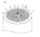
- Fig. 2 is a rear perspective view of a drum with a drum supporting assembly according to an embodiment of the present invention
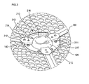
- Fig. 3 is a partial perspective view illustrating a state where a lower housing of a drum supporting unit is mounted on a rear wall of the drum according to an embodiment of the present invention
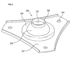
- Fig. 4 is a front perspective view of an upper housing of a drum supporting unit according to an embodiment of the present invention.
- Fig. 5 is a rear perspective view of an upper housing depicted in Fig. 4 ;
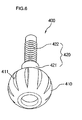
- Fig. 6 is a perspective view of a journal bearing of a drum supporting unit according to an embodiment of the present invention.
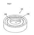
- Fig. 7 is an outer perspective view of an outer seal of a drum supporting unit according to an embodiment of the present invention.
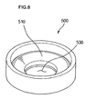
- Fig. 8 is an internal perspective view of an outer seal depicted in Fig. 7 ;
- Fig. 9 is a sectional view taken along line I-I' of Fig. 2 .
- Fig. 1 is a sectional view of a condenser-type laundry dryer with a condenser assembly according to an embodiment of the present invention.
- a condenser-type laundry dryer 30 includes a cabinet 10, a cylindrical drum 100 mounted in the cabinet 10 to receive the laundry therein, a door 13 controlling the opening of the drum 100, a belt 11 disposed around an outer circumference of the drum 100 to rotate the drum 100, and a journal bearing 400 for supporting the drum 100 on the cabinet 10.
- the front portion of the drum 100 is supported by a front portion of the cabinet 10.
- the condenser-type laundry dryer 30 further includes a motor shaft 21 connected to the belt 11 to transmit rotational force to the drum 100, a motor 17 for transmitting the rotational force to the motor shaft 21, and a cooling fan 16 connected to a first end of the motor shaft 21 to rotate by receiving the rotational force of the motor 17 and intake interior air.
- the laundry dryer 30 further includes a dry fan 18 connected to a second end of the motor shaft 15 to circulate air in the drum 100, a dry duct 19 defining a passage for transmitting air introduced by the dry fan 18 to the drum 100, and a heat generating unit 20 mounted in the dry duct 19.
- the laundry dryer further includes a door lint filter 14 formed on a rear surface of the door 13 for primarily filtering foreign objects contained in the circulating air and a body lint filter 15a for secondary filtering foreign objects contained in the circulating air passing through the door lint filter 14.
- a circulation duct 15 along which the circulating air passing through the body lint filter 15a is directed to a condenser (not shown).
- the motor 17 When electric power is applied to the dryer, the motor 17 is operated and the heater 20 mounted in the dry duct 19 is heated. Then, the belt 11 connected to the motor shaft 21 rotates to rotate the drum 100. As the drum 100 rotates, the laundry in the drum 100 is lifted and dropt by a lift (not shown) mounted on the inner wall of the drum 100.
- the dry fan 18 connected to the motor shaft 21 rotates by the rotation of the motor 17 to introduce the circulating air via the condenser.
- the air flows upward along the dry duct 19 and passes through the heater 20 to be converted into high-temperature/dry air. Then, the air is directed into the drum to absorb the moisture contained in the laundry, thereby being converted into the high-temperature/damp air.
- the high-temperature/damp air is directed to the condenser along the circulation duct 15 via the door lint filter 14 and the body lint filter 15a.
- the high-temperature/damp air gives heat to the interior air as it goes through the condenser, thereby being changed into low-temperature/damp air, in the coursed of which the moisture contained in the low-temperature/damp air is condensed.
- the condensed moisture is dropt on the surface of the condenser 200 and is then directed to a sump (not shown).
- the moisture directed to the sump is transmitted to a drawer (not shown) disposed on an upper portion of the dryer 300.
- the interior air passing trough the condenser 200 takes the heat from the high-temperature/damp air to change the circulating air into the low-temperature/damp air. As a result, the temperature of the interior air is increased.
- Fig. 2 shows a rear perspective view of the drum with a drum supporting assembly according to an embodiment of the present invention.
- a rear surface of the drum 100 includes a drum rear wall 110 and a drum supporting unit attached on a center of the drum rear wall 110.
- the drum rear wall 110 is provided with a plurality of circulation air passage holes 120 for directing high temperature/dry air from the dry duct 19 into the drum 100 and a central drum seating groove (140 in Fig. 3 ) for supporting the drum supporting unit 200.
- the supporting unit 200 includes a housing 300 having upper and lower housings 210 and 220 and a journal bearing 400 inserted in the housing 300 to support the drum 100.
- the drum rear wall 110 is concaved by a predetermined depth at a location spaced away from an edge. A portion where the circulating air passage holes 120 are formed is elevated by a predetermined height. Accordingly, the heights of the edge and the portion where the circulating air passage holes 120 are formed the of the rear wall 110 are almost identical to each other.
- the drum rear wall 110 is further provided with load supporting surfaces 130 formed to be lower than the portion where the circulating air passage holes 120 are formed.
- the load supporting surfaces 130 are formed in a radial direction from the center of the rear wall 110. That is, the drum rear wall 110 is divided into a plurality of sections.
- a load of the drum and laundry received in the drum 100 is transmitted to the journal bearing unit 200 mounted on the drum 100.
- the load transmitted to the journal bearing unit 200 is dispersed along the load supporting surfaces 130 of the drum rear wall 110.
- the drum rear wall 110 is provided with a plurality of circulating air passage holes 120, when the drum rear wall 110 is subject to the load corresponding to the drum 100, the drum rear wall 110 may be deformed.
- the load supporting surfaces 130 are provided to prevent this. Accordingly, the load supporting surfaces 130 function to disperse the load applied to the drum rear wall 110 and to prevent the deformation of the drum rear wall 110.
- the load supporting surfaces 130 are disposed and spaced away from each other at an identical angular distances, preferably, by 120°.
- Fig. 3 shows a front perspective view of a condenser according to an embodiment of the present invention.
- the lower housing 210 is mounted on the seating groove 140 of the drum supporting unit formed on the center of the drum rear wall 110.
- the lower housing 210 is coupled to the upper housing 220 and the journal bearing 400 is inserted in the lower housing so that the drum 100 is supported on the rear portion of the dryer.
- the lower housing 210 includes a circular main body 217, a bearing seating portion 215 elevated from the center of the main body 217, a coupling end 212 formed extending from the bearing seating portion 215 and coupled to the upper housing 220, and a coupling member 211 coupled to the drum rear wall 110.
- the bearing seating portion 215 is concaved by a predetermined depth to receive the journal bearing 400.
- the coupling member 211 By the coupling member 211, the lower housing 210 is rivet-coupled to the drum rear wall 110, whereby the damage of the laundry by the projection of the coupling member into the drum 100 can be prevented.
- the present invention is not limited to this rivet coupling.
- the coupling end 212 is bent from the main body 217 and elevated by a predetermined height. Accordingly, the coupling member penetrating the coupling end 212 does not interfere with the drum rear wall 110. Even when the end of the coupling end 212 extends from the outer circumference of the main body 217 in the radial direction, it does not interfere with the drum rear wall 110.
- the coupling end 212 is formed on an identical line to the respective load supporting surfaces 130.
- the coupling end 212 is provided with a coupling hole 214 in which a coupling member for coupling the upper housing 220 will be inserted.
- a sub-coupling hole 213 is formed at a portion spaced away from the coupling hole 214 so that a sub-coupling projection 223 (see fig. 5 ) projected at the upper housing 220 can be inserted therein.
- an inner seal contacting surface 216 may be formed around the concave portion formed on the upper surface of the bearing seating portion 215. Lubricant is deposited on the concave portion to reduce the frictional force with the journal bearing 400.
- Fig. 4 shows a rear perspective view of a condenser depicted in Fig. 3
- Fig. 5 shows a side perspective view of a condenser depicted in Fig. 3 .
- the upper housing 220 is coupled to the lower housing 210 as described above.
- the upper housing 220 includes a main body 227, an inner seal seating portion 226 concaved by a predetermined depth at a center of the main body 227 to receive the inner seal 230, a bearing receiving portion 222 further concaved from the inner seal seating portion 226 to receive the journal bearing 400, and a cylindrical supporting sleeve 225 extending from the top of the bearing receiving portion 222 by a predetermined length.
- the bearing receiving portion 222 is rounded with a curvature identical to that of the bearing (410 in Fig. 6 ) mounted on an end of the journal bearing 400.
- a shaft (420 in Fig. 6 ) of the journal bearing 400 penetrates into the supporting sleeve 225.
- a portion contacting the upper housing coupling end 212 of the lower housing 210 is formed to be longer than other portions. Accordingly, the main body 227 of the upper housing is formed in a triangular shape.
- the main body 227 of the upper housing may be varied without departing from the concept of the present invention.
- the main body 227 of the upper housing is provided with a coupling hole 224 aligned with the coupling hole 214 formed on the coupling end of the lower housing 210.
- the upper housing 220 is further provided with a sub-coupling projection 223 inserted in the sub-coupling hole 213 of the lower housing 210.
- the sub-coupling projection 223 is formed at a portion spaced away from the coupling hole 224. Accordingly, it can be noted that locations where the coupling hole 214 of the lower housing 210 and sub-coupling hole 213 of the lower housing are identical to those where the coupling hole 224 and sub-coupling projection 223 of the upper housing 220.
- the sub-coupling projection 223 is formed at two or more locations to prevent the upper housing 220 from moving in a state where the upper housing 220 is sub-coupled to the lower housing 210.
- the sub-coupling hole 213 formed on the lower housing 210 is formed on the entire portion of the coupling end 212 of the upper housing so that the sub-coupling projection 223 can be inserted into the sub-coupling hole 213 regardless of the seating location of the upper housing 220.
- the sub-coupling projection 223 may be formed on the lower housing 210 and the insertion hole in which the sub-coupling projection 223 is inserted may be formed on the upper housing 220.
- the circular inner seal 230 is disposed on the inner seal seating portion 226 formed on the upper housing 220. That is, by seating the inner seal 230 on an inner side of the upper housing 220, the leakage of the lubricant out of the bearing receiving portion 222 can be prevented.
- the inner seal 230 may be formed of pelt material that can effectively absorb noise and prevent the leakage of the lubricant.
- Fig. 6 shows a perspective view of a journal bearing of a drum supporting unit according to an embodiment of the present invention.
- the journal bearing 400 of the present invention includes a bearing 410 receiving in the housing 300 and a shaft 420 extending from the bearing 410 and penetrating the rear surface of the dryer.
- the bearing is provided at an outer circumference with a plurality of grooves 411 so that the lubricant can be uniformly deposited on the inner circumference of the housing 300.
- the oil grooves 411 are formed in a direction of an axis of the shaft 420 to allow the lubricant deposited on the inner circumference of the housing 300 to effectively move.
- An end of the bearing 410 is cut in a direction perpendicular to a central axis of the shaft 420. Accordingly, a predetermined space is defined between the bottom of the bearing 410 and the bearing seating portion 215.
- the lubricant adhered to the oil grooves 411 is collected in the space after flowing downward. The lubricant flows along the space and the oil grooves as the drum 100 rotates, thereby depositing the whole surface of the bearing.
- the shaft 420 of the journal bearing 400 is inserted in the central portion of the bearing 410, including a shaft body 421 and a back cover coupling portion 422 extending from an end of the shaft body 421 and provided at an outer circumference with a thread.
- the shaft body 421 is coupled on the bearing 410 through an insert injection molding process. A portion of the shaft body 421, which is exposed to an outer circumference of the bearing 410 by a predetermined length, is inserted into the supporting sleeve 225 of the upper housing 220 when the journal bearing 400 is coupled to the housing 300.
- the back cover coupling portion 422 is coupled to a back cover (not shown) defining a rear surface of the dryer after penetrating the supporting sleeve 225 of the upper housing 220.
- the back cover coupling portion 422 is projected to an outer side after penetrating the back cover.
- a nut is fitted on the projected portion of the back cover coupling portion 422 so that the rear portion of the drum 100 can be supported on the back cover.
- Fig. 7 shows an outer perspective view of an outer seal of a drum supporting unit according to an embodiment of the present invention
- Fig. 8 is an internal perspective view of an outer seal depicted in Fig. 7 .
- an outer seal 500 is inserted around the supporting sleeve 225 of the upper housing 220.
- An inner diameter of the outer seal 500 is identical to an outer diameter of the supporting sleeve 225 to prevent the lubricant in the housing 300 from being leaked out of the upper housing 220.
- the outer seal 500 includes a body 600 formed of metal and a rubber seal covering the body 600 through an insert injection molding process. Accordingly, the deformation of the outer seal 500 can be prevented by the metal body 600.
- a dual-layer is formed in the outer seal 500.
- the dual layer includes an inner layer 510 formed on an inner surface of the outer seal 500 and an outer layer 520 formed on an outer portion of the inner layer 510 to define an outer circumference of the outer seal 500.
- the back cover coupling hole 530 penetrating the back cover coupling portion 422 of the journal bearing 400 is formed on the inner portion of the dual-layer. That is, end portions of the inner and outer layers 510 and 520 encloses an outer circumference of the back cover coupling portion 422 to prevent the lubricant from being leaked along the outer circumference of the back cover coupling portion 422. Since the inner and outer layers 510 and 520 are layered, the leakage of the lubricant can be dually prevented.
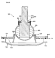
- Fig. 9 shows a sectional view taken along line I-I' of Fig. 2 .
- the drum supporting portion 200 is seated on the drum supporting seating groove 140 formed on the central portion of the drum rear wall 110.
- the lower housing 210 is coupled to the drum supporting seating groove 140 by a rivet.
- the bearing 410 of the journal bearing 400 is seated on the bearing seating portion 215 of the lower housing 210.
- the upper housing 220 is fitted around the shaft 420 of the journal bearing 400 and seated on the top of the lower housing 210.
- the upper and lower housings 220 and 210 are coupled to each other by the coupling member 610.
- the outer seal 500 is seated on the top of the upper housing 220 (on the outer circumference of the supporting sleeve 225.
- the back cover coupling portion 422 of the journal bearing 400 penetrates the back cover of the dryer.
- a nut member is inserted around the outer circumference of the back cover coupling portion 422 so that the shaft 420 can be supported on the back cover.
- the housing 300 and outer seal 500 coupled to the drum rear wall 110 rotates together.
- the journal bearing 400 coupled to the back cover does not rotate but maintains the fixed state. Accordingly, when the drum 100 rotates, the inner circumference of the bearing receiving portion 222 of the upper housing 220 conflicts with the outer circumference of the bearing 410. At this point, the lubricant stored in the bearing receiving portion 222 attenuates the frictional force between the inner circumference of the bearing receiving portion 222 and the outer circumference of the bearing 410.
Landscapes
- Engineering & Computer Science (AREA)
- General Engineering & Computer Science (AREA)
- Mechanical Engineering (AREA)
- Textile Engineering (AREA)
- Detail Structures Of Washing Machines And Dryers (AREA)
Applications Claiming Priority (6)
| Application Number | Priority Date | Filing Date | Title |
|---|---|---|---|
| KR2003094474 | 2003-12-22 | ||
| KR1020030094476A KR100607272B1 (ko) | 2003-12-22 | 2003-12-22 | 건조기의 저널 베어링 조립구조 |
| KR1020030094474A KR100607270B1 (ko) | 2003-12-22 | 2003-12-22 | 건조기의 저널 베어링구조 |
| KR2003094476 | 2003-12-22 | ||
| KR2003094475 | 2003-12-22 | ||
| KR1020030094475A KR100607271B1 (ko) | 2003-12-22 | 2003-12-22 | 건조기의 저널 베어링구조 |
Publications (3)
| Publication Number | Publication Date |
|---|---|
| EP1548176A2 EP1548176A2 (en) | 2005-06-29 |
| EP1548176A3 EP1548176A3 (en) | 2007-05-16 |
| EP1548176B1 true EP1548176B1 (en) | 2013-04-03 |
Family
ID=34557063
Family Applications (1)
| Application Number | Title | Priority Date | Filing Date |
|---|---|---|---|
| EP04293095A Not-in-force EP1548176B1 (en) | 2003-12-22 | 2004-12-22 | Laundry dryer and drum supporting assembly thereof |
Country Status (5)
| Country | Link |
|---|---|
| US (1) | US7748139B2 (zh) |
| EP (1) | EP1548176B1 (zh) |
| JP (1) | JP4792218B2 (zh) |
| CN (1) | CN100478514C (zh) |
| AU (1) | AU2004242439B2 (zh) |
Cited By (1)
| Publication number | Priority date | Publication date | Assignee | Title |
|---|---|---|---|---|
| US11396724B2 (en) * | 2018-11-09 | 2022-07-26 | Samsung Electronics Co., Ltd. | Bearing assembly and clothes dryer having the same |
Families Citing this family (30)
| Publication number | Priority date | Publication date | Assignee | Title |
|---|---|---|---|---|
| US20070266740A9 (en) | 2000-07-25 | 2007-11-22 | Kendall James W | Vertical laundry module |
| KR100556503B1 (ko) * | 2002-11-26 | 2006-03-03 | 엘지전자 주식회사 | 건조기의 건조 시간제어 방법 |
| KR101093878B1 (ko) * | 2004-06-05 | 2011-12-13 | 엘지전자 주식회사 | 건조기의 드럼 장치 |
| KR101093988B1 (ko) * | 2004-06-05 | 2011-12-15 | 엘지전자 주식회사 | 건조기의 도어 린트 필터 밀착 장치 |
| US20070151300A1 (en) | 2005-12-30 | 2007-07-05 | Sunshine Richard A | Modular laundry system with horizontal module spanning two laundry appliances |
| US20070151306A1 (en) | 2005-12-30 | 2007-07-05 | Gilboe Kevin J | Modular laundry system with work surface |
| US20070151303A1 (en) | 2005-12-30 | 2007-07-05 | Doyle Colleen M | Modular laundry system with work surface having a functional element |
| US20060117810A1 (en) | 2004-10-22 | 2006-06-08 | Kendall James W | Modular Laundry system with segmented work surface |
| US11255040B2 (en) | 2004-10-22 | 2022-02-22 | Whirlpool Corporation | Modular laundry system |
| US20070151304A1 (en) | 2005-12-30 | 2007-07-05 | Kendall James W | Modular laundry system with work surface having a functional insert |
| EP1809805B1 (en) * | 2004-11-10 | 2014-10-22 | LG Electronics Inc. | Dryer |
| ES2485340T3 (es) * | 2004-12-06 | 2014-08-13 | Lg Electronics Inc. | Secadora de ropa |
| DE102006002713A1 (de) * | 2005-03-18 | 2006-10-12 | BSH Bosch und Siemens Hausgeräte GmbH | Frontbaugruppe für eine Wäschetrockenmaschine |
| DE102006023951B4 (de) * | 2005-05-23 | 2012-02-09 | Lg Electronics Inc. | Trockner und Trommelhaltervorrichtung dafür |
| DE102005013053A1 (de) * | 2005-05-23 | 2006-11-30 | BSH Bosch und Siemens Hausgeräte GmbH | Kondensations-Wäschetrockner |
| US7518619B2 (en) * | 2005-11-07 | 2009-04-14 | General Electric Company | Method and apparatus for integrating three-dimensional and two-dimensional monitors with medical diagnostic imaging workstations |
| US7913419B2 (en) * | 2005-12-30 | 2011-03-29 | Whirlpool Corporation | Non-tumble clothes dryer |
| DE102006023389A1 (de) * | 2006-05-17 | 2007-11-22 | Herbert Kannegiesser Gmbh | Verfahren und Vorrichtung zum Behandeln, vorzugsweise Waschen, Schleudern und/oder Trocknen, von Wäsche |
| CN101078173B (zh) * | 2006-05-23 | 2011-06-08 | 南京乐金熊猫电器有限公司 | 烘干机的滚筒支撑结构 |
| CA2554497C (en) * | 2006-07-28 | 2010-02-16 | Mabe Canada Inc. | Blower wheel attachment for clothes dryer |
| DE102007046068B4 (de) * | 2006-10-02 | 2018-06-28 | Lg Electronics Inc. | Vorrichtung zum Erkennen einer Riementrennung bei einem Trockner sowie Verfahren zum Erkennen dieses Vorgangs |
| DE102007049959A1 (de) * | 2007-10-18 | 2009-04-23 | BSH Bosch und Siemens Hausgeräte GmbH | Flusenfiltervorrichtung und Hausgerät mit einer derartigen Flusenfiltervorrichtung |
| KR101308510B1 (ko) * | 2007-11-05 | 2013-09-12 | 동부대우전자 주식회사 | 히터 내장형 흡기관을 구비하는 건조기 |
| KR101256145B1 (ko) * | 2007-11-05 | 2013-04-23 | 동부대우전자 주식회사 | 히터 내장형 흡기관을 구비하는 건조기 |
| ES2374767T3 (es) * | 2008-04-30 | 2012-02-21 | Lg Electronics Inc. | Lavadora. |
| KR101608760B1 (ko) | 2008-04-30 | 2016-04-04 | 엘지전자 주식회사 | 의류처리장치 |
| ATE533881T1 (de) | 2008-04-30 | 2011-12-15 | Lg Electronics Inc | Waschmaschine |
| JP2014033758A (ja) * | 2012-08-08 | 2014-02-24 | Panasonic Corp | 衣類乾燥機 |
| EP2990521B1 (en) * | 2014-08-29 | 2017-03-08 | Electrolux Appliances Aktiebolag | Laundry dryer |
| CN110359249A (zh) * | 2018-03-26 | 2019-10-22 | 青岛海尔滚筒洗衣机有限公司 | 一种支撑组件及具有该支撑组件的衣物处理设备 |
Family Cites Families (18)
| Publication number | Priority date | Publication date | Assignee | Title |
|---|---|---|---|---|
| NL151478B (nl) | 1967-03-31 | 1976-11-15 | Philips Nv | Hydrodynamisch glijleger. |
| US3457656A (en) | 1967-11-09 | 1969-07-29 | Westinghouse Electric Corp | Laundry apparatus |
| JPS4611457Y1 (zh) * | 1968-11-13 | 1971-04-21 | ||
| JPS53111669A (en) * | 1977-03-09 | 1978-09-29 | Matsushita Electric Ind Co Ltd | Dewatering washing machine |
| DE2718228C2 (de) * | 1977-04-23 | 1983-10-13 | WOCO Franz-Josef Wolf & Co, 6483 Bad Soden-Salmünster | Kondensatorabdeckscheibe |
| DE7811868U1 (de) | 1978-04-19 | 1978-08-10 | Bosch-Siemens Hausgeraete Gmbh, 7000 Stuttgart | Waeschetrockner |
| JPS58217818A (ja) | 1982-06-14 | 1983-12-17 | Toshiba Corp | 自動調心軸受 |
| JPS6315975U (zh) * | 1986-07-11 | 1988-02-02 | ||
| JPH02134194A (ja) * | 1988-11-16 | 1990-05-23 | Matsushita Electric Ind Co Ltd | 洗濯機 |
| US5121999A (en) * | 1991-03-21 | 1992-06-16 | Emerson Electric Co. | Bearing assembly with seal and shield |
| DE4318897A1 (de) | 1993-06-07 | 1994-12-08 | Bosch Siemens Hausgeraete | Wäschetrockner mit horizontal drehbar gelagerter Wäschetrommel |
| US5407310A (en) * | 1993-10-19 | 1995-04-18 | Agape Plastics, Inc. | Mounting plate assembly |
| US6374700B1 (en) * | 1993-12-03 | 2002-04-23 | Chrysler Corporation | Transmission/transfer case extensionless output arrangement |
| JP3068751B2 (ja) * | 1994-07-29 | 2000-07-24 | シャープ株式会社 | ドラム式洗濯機 |
| JP3840734B2 (ja) * | 1997-03-31 | 2006-11-01 | 松下電器産業株式会社 | ドラム式洗濯機 |
| US6250639B1 (en) * | 1999-01-13 | 2001-06-26 | Fmc Corporation | Idler roll wet seal |
| US6082022A (en) * | 1999-05-05 | 2000-07-04 | Camco Inc. | Clothes dryer drum rear end head |
| KR100480928B1 (ko) | 2003-08-12 | 2005-04-07 | 엘지전자 주식회사 | 의류건조기의 드럼에 장착되는 베어링 장치 |
-
2004
- 2004-12-21 US US11/016,936 patent/US7748139B2/en not_active Expired - Fee Related
- 2004-12-22 CN CNB200410104983XA patent/CN100478514C/zh not_active Expired - Fee Related
- 2004-12-22 AU AU2004242439A patent/AU2004242439B2/en not_active Ceased
- 2004-12-22 EP EP04293095A patent/EP1548176B1/en not_active Not-in-force
- 2004-12-22 JP JP2004371847A patent/JP4792218B2/ja not_active Expired - Fee Related
Cited By (1)
| Publication number | Priority date | Publication date | Assignee | Title |
|---|---|---|---|---|
| US11396724B2 (en) * | 2018-11-09 | 2022-07-26 | Samsung Electronics Co., Ltd. | Bearing assembly and clothes dryer having the same |
Also Published As
| Publication number | Publication date |
|---|---|
| US20050132604A1 (en) | 2005-06-23 |
| US7748139B2 (en) | 2010-07-06 |
| EP1548176A3 (en) | 2007-05-16 |
| CN100478514C (zh) | 2009-04-15 |
| AU2004242439A1 (en) | 2005-07-07 |
| AU2004242439B2 (en) | 2010-09-23 |
| JP2005177513A (ja) | 2005-07-07 |
| EP1548176A2 (en) | 2005-06-29 |
| JP4792218B2 (ja) | 2011-10-12 |
| CN1637203A (zh) | 2005-07-13 |
Similar Documents
| Publication | Publication Date | Title |
|---|---|---|
| EP1548176B1 (en) | Laundry dryer and drum supporting assembly thereof | |
| US7036243B2 (en) | Laundry dryer and condenser assembly thereof | |
| EP1541741B1 (en) | Laundry dryer | |
| US7523564B2 (en) | Dryer and drum supporting apparatus thereof | |
| EP1541743A1 (en) | Laundry dryer with dry board | |
| US20050229650A1 (en) | Drum type washing machine with laundry drying function | |
| EP3039180B1 (en) | Rotary-drum heat-pump laundry dryer | |
| EP1548172B1 (en) | Dryer, and motor mounting structure of the same | |
| EP3039181B1 (en) | Rotary-drum laundry dryer | |
| EP2843115B1 (en) | Rotary-drum laundry dryer | |
| KR100607272B1 (ko) | 건조기의 저널 베어링 조립구조 | |
| KR100607271B1 (ko) | 건조기의 저널 베어링구조 | |
| KR100607270B1 (ko) | 건조기의 저널 베어링구조 | |
| JP2024535611A (ja) | 衣類処理装置 | |
| KR20220114165A (ko) | 의류처리장치 | |
| JP2024535620A (ja) | 衣類処理装置 | |
| KR20230111120A (ko) | 의류처리장치 |
Legal Events
| Date | Code | Title | Description |
|---|---|---|---|
| PUAI | Public reference made under article 153(3) epc to a published international application that has entered the european phase |
Free format text: ORIGINAL CODE: 0009012 |
|
| AK | Designated contracting states |
Kind code of ref document: A2 Designated state(s): AT BE BG CH CY CZ DE DK EE ES FI FR GB GR HU IE IS IT LI LT LU MC NL PL PT RO SE SI SK TR |
|
| AX | Request for extension of the european patent |
Extension state: AL BA HR LV MK YU |
|
| PUAL | Search report despatched |
Free format text: ORIGINAL CODE: 0009013 |
|
| AK | Designated contracting states |
Kind code of ref document: A3 Designated state(s): AT BE BG CH CY CZ DE DK EE ES FI FR GB GR HU IE IS IT LI LT LU MC NL PL PT RO SE SI SK TR |
|
| AX | Request for extension of the european patent |
Extension state: AL BA HR LV MK YU |
|
| 17P | Request for examination filed |
Effective date: 20071112 |
|
| AKX | Designation fees paid |
Designated state(s): DE ES FR GB IT |
|
| 17Q | First examination report despatched |
Effective date: 20110823 |
|
| RIC1 | Information provided on ipc code assigned before grant |
Ipc: D06F 58/06 20060101AFI20120723BHEP Ipc: F16C 23/04 20060101ALI20120723BHEP |
|
| GRAP | Despatch of communication of intention to grant a patent |
Free format text: ORIGINAL CODE: EPIDOSNIGR1 |
|
| GRAS | Grant fee paid |
Free format text: ORIGINAL CODE: EPIDOSNIGR3 |
|
| GRAA | (expected) grant |
Free format text: ORIGINAL CODE: 0009210 |
|
| AK | Designated contracting states |
Kind code of ref document: B1 Designated state(s): DE ES FR GB IT |
|
| REG | Reference to a national code |
Ref country code: GB Ref legal event code: FG4D |
|
| REG | Reference to a national code |
Ref country code: DE Ref legal event code: R096 Ref document number: 602004041564 Country of ref document: DE Effective date: 20130529 |
|
| PG25 | Lapsed in a contracting state [announced via postgrant information from national office to epo] |
Ref country code: ES Free format text: LAPSE BECAUSE OF FAILURE TO SUBMIT A TRANSLATION OF THE DESCRIPTION OR TO PAY THE FEE WITHIN THE PRESCRIBED TIME-LIMIT Effective date: 20130714 |
|
| PLBE | No opposition filed within time limit |
Free format text: ORIGINAL CODE: 0009261 |
|
| STAA | Information on the status of an ep patent application or granted ep patent |
Free format text: STATUS: NO OPPOSITION FILED WITHIN TIME LIMIT |
|
| PG25 | Lapsed in a contracting state [announced via postgrant information from national office to epo] |
Ref country code: IT Free format text: LAPSE BECAUSE OF FAILURE TO SUBMIT A TRANSLATION OF THE DESCRIPTION OR TO PAY THE FEE WITHIN THE PRESCRIBED TIME-LIMIT Effective date: 20130403 |
|
| 26N | No opposition filed |
Effective date: 20140106 |
|
| REG | Reference to a national code |
Ref country code: DE Ref legal event code: R097 Ref document number: 602004041564 Country of ref document: DE Effective date: 20140106 |
|
| PGFP | Annual fee paid to national office [announced via postgrant information from national office to epo] |
Ref country code: DE Payment date: 20141111 Year of fee payment: 11 Ref country code: GB Payment date: 20141111 Year of fee payment: 11 Ref country code: FR Payment date: 20141111 Year of fee payment: 11 |
|
| REG | Reference to a national code |
Ref country code: DE Ref legal event code: R119 Ref document number: 602004041564 Country of ref document: DE |
|
| GBPC | Gb: european patent ceased through non-payment of renewal fee |
Effective date: 20151222 |
|
| REG | Reference to a national code |
Ref country code: FR Ref legal event code: ST Effective date: 20160831 |
|
| PG25 | Lapsed in a contracting state [announced via postgrant information from national office to epo] |
Ref country code: GB Free format text: LAPSE BECAUSE OF NON-PAYMENT OF DUE FEES Effective date: 20151222 Ref country code: DE Free format text: LAPSE BECAUSE OF NON-PAYMENT OF DUE FEES Effective date: 20160701 |
|
| PG25 | Lapsed in a contracting state [announced via postgrant information from national office to epo] |
Ref country code: FR Free format text: LAPSE BECAUSE OF NON-PAYMENT OF DUE FEES Effective date: 20151231 |