EP1545835B1 - Durchflusssteuerungssystem - Google Patents
Durchflusssteuerungssystem Download PDFInfo
- Publication number
- EP1545835B1 EP1545835B1 EP20030799281 EP03799281A EP1545835B1 EP 1545835 B1 EP1545835 B1 EP 1545835B1 EP 20030799281 EP20030799281 EP 20030799281 EP 03799281 A EP03799281 A EP 03799281A EP 1545835 B1 EP1545835 B1 EP 1545835B1
- Authority
- EP
- European Patent Office
- Prior art keywords
- fluid
- control system
- flow control
- process fluid
- outlet
- Prior art date
- Legal status (The legal status is an assumption and is not a legal conclusion. Google has not performed a legal analysis and makes no representation as to the accuracy of the status listed.)
- Expired - Lifetime
Links
Images
Classifications
-
- B—PERFORMING OPERATIONS; TRANSPORTING
- B24—GRINDING; POLISHING
- B24B—MACHINES, DEVICES, OR PROCESSES FOR GRINDING OR POLISHING; DRESSING OR CONDITIONING OF ABRADING SURFACES; FEEDING OF GRINDING, POLISHING, OR LAPPING AGENTS
- B24B37/00—Lapping machines or devices; Accessories
- B24B37/04—Lapping machines or devices; Accessories designed for working plane surfaces
-
- H—ELECTRICITY
- H10—SEMICONDUCTOR DEVICES; ELECTRIC SOLID-STATE DEVICES NOT OTHERWISE PROVIDED FOR
- H10P—GENERIC PROCESSES OR APPARATUS FOR THE MANUFACTURE OR TREATMENT OF DEVICES COVERED BY CLASS H10
- H10P52/00—Grinding, lapping or polishing of wafers, substrates or parts of devices
-
- B—PERFORMING OPERATIONS; TRANSPORTING
- B24—GRINDING; POLISHING
- B24B—MACHINES, DEVICES, OR PROCESSES FOR GRINDING OR POLISHING; DRESSING OR CONDITIONING OF ABRADING SURFACES; FEEDING OF GRINDING, POLISHING, OR LAPPING AGENTS
- B24B57/00—Devices for feeding, applying, grading or recovering grinding, polishing or lapping agents
- B24B57/02—Devices for feeding, applying, grading or recovering grinding, polishing or lapping agents for feeding of fluid, sprayed, pulverised, or liquefied grinding, polishing or lapping agents
-
- G—PHYSICS
- G05—CONTROLLING; REGULATING
- G05D—SYSTEMS FOR CONTROLLING OR REGULATING NON-ELECTRIC VARIABLES
- G05D7/00—Control of flow
- G05D7/06—Control of flow characterised by the use of electric means
- G05D7/0617—Control of flow characterised by the use of electric means specially adapted for fluid materials
- G05D7/0629—Control of flow characterised by the use of electric means specially adapted for fluid materials characterised by the type of regulator means
- G05D7/0676—Control of flow characterised by the use of electric means specially adapted for fluid materials characterised by the type of regulator means by action on flow sources
-
- Y—GENERAL TAGGING OF NEW TECHNOLOGICAL DEVELOPMENTS; GENERAL TAGGING OF CROSS-SECTIONAL TECHNOLOGIES SPANNING OVER SEVERAL SECTIONS OF THE IPC; TECHNICAL SUBJECTS COVERED BY FORMER USPC CROSS-REFERENCE ART COLLECTIONS [XRACs] AND DIGESTS
- Y10—TECHNICAL SUBJECTS COVERED BY FORMER USPC
- Y10T—TECHNICAL SUBJECTS COVERED BY FORMER US CLASSIFICATION
- Y10T137/00—Fluid handling
- Y10T137/206—Flow affected by fluid contact, energy field or coanda effect [e.g., pure fluid device or system]
- Y10T137/218—Means to regulate or vary operation of device
Definitions
- the present invention relates generally to fluid flow and control, and more particularly, to a fluid flow control system suitable for use in ultra-pure or corrosive applications.
- CMP Chemical-Mechanical Planarization
- a slurry-coated polishing pad rotates at a controlled speed against the semiconductor wafer to flatten the surface.
- the slurry contains chemicals that soften the surface chemically as well as abrasives that work with the polishing pad to mechanically polish the surface.
- the mechanical and chemical polishing must work together in a delicate balance - any changes to this balance can cause damage to the wafer or reduce yield. If there is no slurry, then all of the polishing is mechanical and it would be like polishing glass with sandpaper. If there is too much slurry, most of the polishing is chemical and again the balance is off.
- the polishing rate of the wafer is highly dependent upon the delivery rate of the fluid and the total amount of fluid delivered during a polishing operation.
- the slurry delivery system typically includes a positive displacement pump, such as a peristaltic pump, to draw the slurry from a vessel and apply it to the polishing pad.
- a positive displacement pump such as a peristaltic pump
- the pump moves the fluid at a more or less constant rate depending on the speed of the pump, though the peristaltic pumping action causes a pulsation in the fluid delivery rate.
- the peristaltic pump is a volumetric fluid delivery system, the amount of fluid varies with changing conditions such as the pump tube age, the pump tube temperature, the fluid composition, the pump motor speed, the level of fluid in the vessel, pump calibration, etc.
- fluid such as slurry is supplied in a circulating overhead loop.
- slurry loops are often driven with an air actuated diaphragm pump.
- CMP tools may be driven from the same loop. Pressure in the loop my change when one tool draws slurry. This change in loop pressure may affect the slurry flow rate on another tool connected to the same loop.
- a flow control system comprises:
- the rigid vessel comprises a cylinder.
- the movable member comprises a plunger positioned in the cylinder.
- the flow control system further comprises a piston connected to the plunger for activating the plunger.
- the flow control system further comprises a stepper motor operatively connected to the piston for actuating the plunger.
- the inlet and the outlet include inlet and outlet check valves, respectively.
- the plunger is fabricated from PFA.
- the bladder is fabricated from PFA.
- the flow control system further comprises a drive fluid reservoir situated in the rigid vessel.
- the movable member comprises a diaphragm that separates the drive fluid reservoir from the process fluid reservoir.
- the diaphragm is fabricated from PFA.
- the flow control system further comprises a pump in fluid communication with the working fluid reservoir to selectively meter working fluid into and out of the working fluid reservoir, such that metering working fluid out of the working fluid reservoir displaces the diaphragm in the first direction to draw process fluid into the inlet and metering working fluid into the working fluid reservoir displaces the diaphragm in the second direction to expel process fluid from the outlet.
- a pump in fluid communication with the working fluid reservoir to selectively meter working fluid into and out of the working fluid reservoir, such that metering working fluid out of the working fluid reservoir displaces the diaphragm in the first direction to draw process fluid into the inlet and metering working fluid into the working fluid reservoir displaces the diaphragm in the second direction to expel process fluid from the outlet.
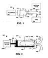
- FIG. 1 is a prior art block diagram conceptually illustrating portions of a flow control system 100.
- the exemplary pump system 100 shown in Figure 1 includes a substantially rigid vessel 110 that includes an inlet 114 and an outlet 116 positioned generally at one side of the rigid vessel 110.
- a process fluid reservoir 112 is situated in the rigid vessel 110 in fluid communication with the inlet 114 and the outlet 116. To expel process fluid from the process fluid reservoir 110, the process fluid reservoir is collapsed as described further herein below.
- the process fluid reservoir 112 is provided pre-filled with process fluid and thus, the inlet 114 is not provided.
- a movable member 120 is positioned in the rigid vessel 110, such that movement of the movable member 120 in a first direction (to the left as shown in Figure 1 ) causes process fluid 122 (for example, slurry for use in a CMP process) to be drawn into the inlet 114 via a supply tube 123. Movement of the movable member 120 in a second direction (to the right as shown in Figure 1 ) collapses the reservoir 112 and causes the process fluid to be expelled from the outlet 116 to a process tool 124 via a process tube 125.
- An actuator 130 selectively controls movement of the movable member 120.
- Inlet and outlet check valves 115,117 are provided at the inlet 114 and the outlet 116.
- the outlet check valve 117 closes and the inlet check valve 115 opens, allowing the process fluid 122 to enter the process fluid reservoir 112.
- the supply pressure may be ambient (for example, if the process fluid 122 is supplied from a bottle), positive (loop pressure) or negative (for example, the process fluid 122 is supplied from a bucket).
- the process fluid loading is independent of variation in mean pressure or pressure pulsation in the process fluid supply. Because the pump system 100 is volumetric in nature, air bubbles are not differentiated from fluid.
- Air collection and purge can be accomplished by several methods. For example, the use of an accumulator, or holding tank, prior to the inlet valve to store fluid and allow the air bubbles to rise to the top, while the process fluid sinks to the bottom. The "bubble-less" process fluid is then drawn into the inlet 114 from the bottom of the tank.
- an intelligent purge is used to release air bubbles - some predetermined volume of process fluid is drawn into the reservoir 112 and another predetermined volume is purged off the top (possibly back into the supply tank). The remaining process fluid is then dispensed.
- FIG. 2 generally illustrates a flow control system 200 in accordance with exemplary embodiments of the invention.
- the flow control system 200 includes a syringe pump 201.
- the rigid vessel is a cylinder 210 having a generally uniform cross-section.
- the cylinder 210 has one end that includes the inlet 114 and the outlet 116, which are connected to the supply tube 123 and the process tube 125 via the inlet and outlet check valves 115,117, respectively.
- a plunger 220 is situated generally opposite the inlet/outlet end of the cylinder 210.
- the plunger 220 is slidable in the cylinder 210 such that movement of the plunger 220 to the right as illustrated in Figure 2 results in process fluid being expelled from the cylinder 210, through the outlet 116 to the process tube 125.
- the cylinder 210 has a generally uniform cross section, so the volumetric flow rate is directly proportional to the plunger velocity.
- a linear drive stepper motor 230 is connected to the plunger 220 via a piston 232 to actuate the plunger 220.
- the stepper motor 230 moves the plunger 220 at a commanded rate (for example, pulses per unit time), even if the downstream pressure changes.
- the pump system 200 can respond to influences in the process essentially instantaneously, as the plunger force adjusts to the level required to keep the plunger 220 moving at the commanded rate.
- the motor current is monitored and used as an indication of problems in the process, such as downstream filter plugging. If the current becomes excessive, the system is shut down before mechanical failure occurs.
- the particular actuator used is based on several factors, including batch size, batch time, inlet pressure, outlet pressure, fluid viscosity, fluid density, etc.
- a bladder 212 is situated in the cylinder 210 such that it is in fluid communication with the inlet 114 and the outlet 116 to form the process fluid reservoir 112.
- the bladder 212 is fastened to the inlet/outlet end of the cylinder 210 such that the process fluid, such as slurry, is isolated from the interior of the cylinder 210 and the plunger 220.
- the process fluid such as slurry
- movement of the plunger in a one direction causes fluid to be drawn into the bladder 212 and movement of the plunger in the opposite direction (to the right as shown in Figure 2 ) causes fluid to be expelled from the bladder 212.
- the fluid supply tube 123 is connected to the inlet 114 via an inlet check valve 115, and the outlet 116 is connected to the process tube 125 via an outlet check valve 117.
- wetted components of the pump system 200 are fabricated of high-purity plastic.
- a suitable high purity plastic is PFA (perfluoroalkoxy copolymer), which is an advanced fluoropolymer with superior chemical resistance and mechanical properties.
- PFA perfluoroalkoxy copolymer
- PVDF perfluoroalkoxy copolymer
- PTFE perfluoroalkoxy copolymer
- these materials are "non-stick" and thus, do not tend to gather particles. This prevents particle build up and clogging of filters due to such build up.
Landscapes
- Engineering & Computer Science (AREA)
- Mechanical Engineering (AREA)
- Physics & Mathematics (AREA)
- General Physics & Mathematics (AREA)
- Automation & Control Theory (AREA)
- Reciprocating Pumps (AREA)
- Grinding-Machine Dressing And Accessory Apparatuses (AREA)
- Flow Control (AREA)
- Feeding, Discharge, Calcimining, Fusing, And Gas-Generation Devices (AREA)
- Finish Polishing, Edge Sharpening, And Grinding By Specific Grinding Devices (AREA)
- Sampling And Sample Adjustment (AREA)
- Catching Or Destruction (AREA)
Claims (8)
- Durchflussregelsystem (200), das Folgendes umfasst:einen im Wesentlichen starren Behälter mit einem ersten und einem zweiten Ende; wobei das erste Ende des starren Behälters (210) einen Einlass (114) undeinen Auslass (116) hat; undein bewegliches Element (220), das so in dem starren Behälter (210) positioniert ist, dass eine Bewegung des beweglichen Elements (220) in einer ersten Richtung bewirkt, dass Prozessfluid in den Einlass (114) eingesaugt wird, und eine Bewegung des beweglichen Elements (220) in einer zweiten Richtung bewirkt, dass Prozessfluid aus dem Auslass (116) ausgestoßen wird;gekennzeichnet durch:eine Blase (212), die sich in dem starren Behälter (210) befindet und einen Prozessfluidvorrat (112) in Fluidverbindung mit dem Einlass (114) und dem Auslass (116) definiert, wobei die genannte Blase (212) so in dem starren Behälter (210) positioniert ist, dass das Prozessfluid vom Innern des starren Behälters (210) isoliert ist.
- Durchflussregelsystem (200) nach Anspruch 1, wobei der starre Behälter (210) einen Zylinder umfasst.
- Durchflussregelsystem (200) nach Anspruch 2, wobei das bewegliche Element (220) einen gleitbar in dem Zylinder positionierten Stößel umfasst.
- Durchflussregelsystem (200) nach Anspruch 3, das ferner einen Kolben (232) umfasst, der mit dem Stößel (200) verbunden ist, um den Stößel (220) zu betätigen.
- Durchflussregelsystem (200) nach Anspruch 4, das ferner einen Schrittmotor (230) umfasst, der mit dem Kolben (232) in Wirkverbindung ist, um den Stößel (220) zu betätigen.
- Durchflussregelsystem (200) nach Anspruch 1, wobei der Einlass (114) und der Auslass (116) jeweils ein Ein- und ein Auslassabsperrventil (115, 117) aufweisen.
- Durchflussregelsystem (200) nach Anspruch 3, wobei der Stößel (220) aus PFA gefertigt ist.
- Durchflussregelsystem (200) nach Anspruch 1, wobei die Blase (212) aus PFA gefertigt ist.
Priority Applications (4)
| Application Number | Priority Date | Filing Date | Title |
|---|---|---|---|
| EP20100012713 EP2343156B1 (de) | 2002-09-30 | 2003-09-10 | Durchflusssteuerungssystem |
| EP20080170886 EP2108482A1 (de) | 2002-09-30 | 2003-09-10 | Durchflusssteuerungssystem |
| EP20100012714 EP2347858A3 (de) | 2002-09-30 | 2003-09-10 | Durchflusssteuerungssystem |
| DK10012713.3T DK2343156T3 (en) | 2002-09-30 | 2003-09-10 | flow Control |
Applications Claiming Priority (3)
| Application Number | Priority Date | Filing Date | Title |
|---|---|---|---|
| US65275 | 1993-05-21 | ||
| US10/065,275 US7204679B2 (en) | 2002-09-30 | 2002-09-30 | Flow control system |
| PCT/US2003/028397 WO2004030860A2 (en) | 2002-09-30 | 2003-09-10 | Flow control system |
Related Child Applications (4)
| Application Number | Title | Priority Date | Filing Date |
|---|---|---|---|
| EP20100012713 Division EP2343156B1 (de) | 2002-09-30 | 2003-09-10 | Durchflusssteuerungssystem |
| EP20080170886 Division EP2108482A1 (de) | 2002-09-30 | 2003-09-10 | Durchflusssteuerungssystem |
| EP08170886.9 Division-Into | 2008-12-05 | ||
| EP08170887.7 Division-Into | 2008-12-05 |
Publications (2)
| Publication Number | Publication Date |
|---|---|
| EP1545835A2 EP1545835A2 (de) | 2005-06-29 |
| EP1545835B1 true EP1545835B1 (de) | 2010-10-27 |
Family
ID=32028515
Family Applications (4)
| Application Number | Title | Priority Date | Filing Date |
|---|---|---|---|
| EP20030799281 Expired - Lifetime EP1545835B1 (de) | 2002-09-30 | 2003-09-10 | Durchflusssteuerungssystem |
| EP20100012714 Withdrawn EP2347858A3 (de) | 2002-09-30 | 2003-09-10 | Durchflusssteuerungssystem |
| EP20100012713 Expired - Lifetime EP2343156B1 (de) | 2002-09-30 | 2003-09-10 | Durchflusssteuerungssystem |
| EP20080170886 Withdrawn EP2108482A1 (de) | 2002-09-30 | 2003-09-10 | Durchflusssteuerungssystem |
Family Applications After (3)
| Application Number | Title | Priority Date | Filing Date |
|---|---|---|---|
| EP20100012714 Withdrawn EP2347858A3 (de) | 2002-09-30 | 2003-09-10 | Durchflusssteuerungssystem |
| EP20100012713 Expired - Lifetime EP2343156B1 (de) | 2002-09-30 | 2003-09-10 | Durchflusssteuerungssystem |
| EP20080170886 Withdrawn EP2108482A1 (de) | 2002-09-30 | 2003-09-10 | Durchflusssteuerungssystem |
Country Status (17)
| Country | Link |
|---|---|
| US (1) | US7204679B2 (de) |
| EP (4) | EP1545835B1 (de) |
| JP (1) | JP4372010B2 (de) |
| KR (1) | KR100649468B1 (de) |
| CN (2) | CN100528485C (de) |
| AR (2) | AR041382A1 (de) |
| AT (1) | ATE485919T1 (de) |
| AU (1) | AU2003266022B2 (de) |
| BR (1) | BR0314955A (de) |
| CA (1) | CA2500543C (de) |
| DE (1) | DE60334712D1 (de) |
| DK (2) | DK1545835T3 (de) |
| MX (1) | MXPA05003444A (de) |
| MY (1) | MY135346A (de) |
| PL (3) | PL206362B1 (de) |
| RU (1) | RU2313004C2 (de) |
| WO (1) | WO2004030860A2 (de) |
Cited By (1)
| Publication number | Priority date | Publication date | Assignee | Title |
|---|---|---|---|---|
| TWI742924B (zh) * | 2020-11-13 | 2021-10-11 | 國立勤益科技大學 | 自動擠膏拋光刀把 |
Families Citing this family (20)
| Publication number | Priority date | Publication date | Assignee | Title |
|---|---|---|---|---|
| AU2005325631A1 (en) * | 2005-01-18 | 2006-07-27 | Zhengcai Zhou | Blasting device for premixed abrasive slurry |
| US7735563B2 (en) * | 2005-03-10 | 2010-06-15 | Hydril Usa Manufacturing Llc | Pressure driven pumping system |
| JP2008539146A (ja) * | 2005-04-25 | 2008-11-13 | アドバンスド テクノロジー マテリアルズ,インコーポレイテッド | 化学試薬及び組成を保存・分配する装置及びプロセス |
| KR100806841B1 (ko) * | 2006-09-11 | 2008-02-22 | 세메스 주식회사 | 슬러리 공급장치에서의 버블 댐퍼 |
| TW200916183A (en) * | 2007-05-09 | 2009-04-16 | Advanced Tech Materials | Systems and methods for material blending and distribution |
| KR20100113074A (ko) * | 2007-12-06 | 2010-10-20 | 포어사이트 프로세싱 엘엘씨 | 유체 함유 공정 재료 화합물의 전달 방법 및 시스템 |
| US20100243087A1 (en) * | 2009-03-03 | 2010-09-30 | Millipore Corporation | System and pump apparatus for processing fluid samples |
| KR20120036953A (ko) * | 2009-06-10 | 2012-04-18 | 어드밴스드 테크놀러지 머티리얼즈, 인코포레이티드 | 유체 가공 시스템 및 방법 |
| US8308854B2 (en) * | 2009-12-15 | 2012-11-13 | Thermo Finnigan Llc | Helium reclamation systems and methods for a gas chromatograph |
| RU2459978C1 (ru) * | 2011-07-26 | 2012-08-27 | Общество с ограниченной ответственностью "Купер" | Насосная установка регулируемая, диафрагменная |
| KR20130090209A (ko) * | 2012-02-03 | 2013-08-13 | 삼성전자주식회사 | 기판처리장치 및 기판처리방법 |
| AU2014236334B2 (en) * | 2013-03-14 | 2018-04-05 | Bio-Rad Laboratories, Inc. | Bottle pressurization delivery system |
| US9770804B2 (en) | 2013-03-18 | 2017-09-26 | Versum Materials Us, Llc | Slurry supply and/or chemical blend supply apparatuses, processes, methods of use and methods of manufacture |
| US9695674B2 (en) * | 2014-04-04 | 2017-07-04 | Onesubsea Ip Uk Limited | Subsea dosing pump |
| WO2015172081A1 (en) * | 2014-05-08 | 2015-11-12 | Baker Hughes Incorporated | Oil injection unit |
| JP6622578B2 (ja) * | 2015-12-08 | 2019-12-18 | 不二越機械工業株式会社 | ワーク加工装置およびこれに用いる薬液収納バッグ |
| CN107096901A (zh) * | 2017-05-02 | 2017-08-29 | 重庆天运汽车配件有限公司 | 一种离心浇铸均匀进液装置 |
| US11251047B2 (en) | 2017-11-13 | 2022-02-15 | Applied Materials, Inc. | Clog detection in a multi-port fluid delivery system |
| JP7194996B2 (ja) * | 2019-03-13 | 2022-12-23 | 株式会社松井製作所 | 流体研磨装置 |
| JP7407439B2 (ja) * | 2019-10-24 | 2024-01-04 | 兵神装備株式会社 | 流体圧送装置 |
Family Cites Families (23)
| Publication number | Priority date | Publication date | Assignee | Title |
|---|---|---|---|---|
| FR945469A (fr) | 1946-03-22 | 1949-05-05 | Passch & Larsen Petersen | Procédé pour prélever une quantité déterminée de beurre ou autre matière plastique aspirées dans une cuve et appareil pour la mise en oeuvre de ce procédé |
| SU97285A1 (ru) | 1952-09-26 | 1953-11-30 | В.В. Залесский | Насос дл перекачки жидкостей с плохими смазывающими свойствами |
| SU125162A1 (ru) | 1959-06-15 | 1959-11-30 | В.М. Данич | Устройство дл подачи абразивных паст в рабочую зону полировального станка |
| US3635607A (en) | 1970-04-20 | 1972-01-18 | Novelty Tool Co Inc | Vacuum pump |
| US3756456A (en) | 1972-05-22 | 1973-09-04 | Graco Inc | Apparatus and method for a metering system |
| SU591609A1 (ru) | 1976-04-26 | 1978-02-05 | Московское Научно-Производственное Объединение По Механизированному Строительному Инструменту И Отделочным Машинам (Объединение "Вниисми") | Поршневой растворонасос |
| SU723215A2 (ru) | 1978-04-04 | 1980-03-25 | Предприятие П/Я В-8662 | Гидро - или пневмоприводной насос |
| SU767528A1 (ru) | 1978-07-06 | 1980-09-30 | Предприятие П/Я В-8644 | Способ непрерывного дозировани жидкости |
| US4488853A (en) * | 1980-08-28 | 1984-12-18 | New Process Industries, Inc. | Fluid pressure ratio transformer system |
| US4863066A (en) | 1986-06-02 | 1989-09-05 | Technicon Instruments Corporation | System for dispensing precisely metered quantities of a fluid and method of utilizing the system |
| FR2608225B1 (fr) | 1986-12-10 | 1989-02-17 | Imaje Sa | Cellule a multiples fonctions comportant une chambre a volume variable, et circuit d'alimentation fluide d'une tete d'impression a jet d'encre qui en est equipe |
| US4950134A (en) * | 1988-12-27 | 1990-08-21 | Cybor Corporation | Precision liquid dispenser |
| US5056036A (en) | 1989-10-20 | 1991-10-08 | Pulsafeeder, Inc. | Computer controlled metering pump |
| FR2706857B1 (de) | 1993-06-25 | 1995-10-27 | Dussau Distribution Sarl | |
| US5753515A (en) | 1996-07-02 | 1998-05-19 | Eastman Kodak Company | Syringe pump apparatus for remote delivery of reactants |
| NL1004637C2 (nl) | 1996-11-28 | 1998-05-29 | Daniel Van Beek | Doseerinrichting. |
| US5971722A (en) | 1997-09-05 | 1999-10-26 | Baxter International Inc | Electrochemical syringe pump having a sealed storage reservoir for a charge transfer medium |
| US6293849B1 (en) * | 1997-10-31 | 2001-09-25 | Ebara Corporation | Polishing solution supply system |
| US5945346A (en) * | 1997-11-03 | 1999-08-31 | Motorola, Inc. | Chemical mechanical planarization system and method therefor |
| US6107203A (en) * | 1997-11-03 | 2000-08-22 | Motorola, Inc. | Chemical mechanical polishing system and method therefor |
| US6109881A (en) * | 1998-01-09 | 2000-08-29 | Snodgrass; Ocie T. | Gas driven pump for the dispensing and filtering of process fluid |
| US6254453B1 (en) * | 1999-09-30 | 2001-07-03 | International Business Machines Corporation | Optimization of chemical mechanical process by detection of oxide/nitride interface using CLD system |
| US6544109B1 (en) * | 2000-08-31 | 2003-04-08 | Micron Technology, Inc. | Slurry delivery and planarization systems |
-
2002
- 2002-09-30 US US10/065,275 patent/US7204679B2/en not_active Expired - Lifetime
-
2003
- 2003-09-10 WO PCT/US2003/028397 patent/WO2004030860A2/en not_active Ceased
- 2003-09-10 EP EP20030799281 patent/EP1545835B1/de not_active Expired - Lifetime
- 2003-09-10 BR BR0314955A patent/BR0314955A/pt not_active Application Discontinuation
- 2003-09-10 EP EP20100012714 patent/EP2347858A3/de not_active Withdrawn
- 2003-09-10 MX MXPA05003444A patent/MXPA05003444A/es active IP Right Grant
- 2003-09-10 PL PL388178A patent/PL206362B1/pl unknown
- 2003-09-10 DK DK03799281.5T patent/DK1545835T3/da active
- 2003-09-10 RU RU2005113299A patent/RU2313004C2/ru active
- 2003-09-10 JP JP2004541523A patent/JP4372010B2/ja not_active Expired - Lifetime
- 2003-09-10 AT AT03799281T patent/ATE485919T1/de not_active IP Right Cessation
- 2003-09-10 CN CNB038254808A patent/CN100528485C/zh not_active Expired - Lifetime
- 2003-09-10 EP EP20100012713 patent/EP2343156B1/de not_active Expired - Lifetime
- 2003-09-10 AU AU2003266022A patent/AU2003266022B2/en not_active Expired
- 2003-09-10 KR KR1020057005550A patent/KR100649468B1/ko not_active Expired - Fee Related
- 2003-09-10 DK DK10012713.3T patent/DK2343156T3/en active
- 2003-09-10 PL PL388177A patent/PL206361B1/pl unknown
- 2003-09-10 CN CN2009100045957A patent/CN101491889B/zh not_active Expired - Lifetime
- 2003-09-10 PL PL375436A patent/PL206360B1/pl unknown
- 2003-09-10 DE DE60334712T patent/DE60334712D1/de not_active Expired - Lifetime
- 2003-09-10 EP EP20080170886 patent/EP2108482A1/de not_active Withdrawn
- 2003-09-10 CA CA002500543A patent/CA2500543C/en not_active Expired - Lifetime
- 2003-09-24 AR ARP030103480 patent/AR041382A1/es active IP Right Grant
- 2003-09-26 MY MYPI20033686A patent/MY135346A/en unknown
-
2009
- 2009-04-24 AR ARP090101466 patent/AR071409A2/es active IP Right Grant
Cited By (1)
| Publication number | Priority date | Publication date | Assignee | Title |
|---|---|---|---|---|
| TWI742924B (zh) * | 2020-11-13 | 2021-10-11 | 國立勤益科技大學 | 自動擠膏拋光刀把 |
Also Published As
Similar Documents
| Publication | Publication Date | Title |
|---|---|---|
| EP1545835B1 (de) | Durchflusssteuerungssystem | |
| CN100480929C (zh) | 在cmp/清洗系统中现场输送、控制和混合化学药剂和浆体的系统与方法 | |
| EP2026041A2 (de) | Abgabesystem für hochreine Flüssigkeiten | |
| AU2002365579B2 (en) | High purity coriolis mass flow controller | |
| JP2003509627A (ja) | 精密供出ポンプ及び供出方法 | |
| CN110088472B (zh) | 医用液体的容积泵和血液治疗设备及其控制的方法 | |
| EP3315974A1 (de) | Spendervorrichtung | |
| CN115213062A (zh) | 液体供给装置 | |
| HK1129628B (en) | A method of controlling the flow of slurry to a cmp tool | |
| HK1086523B (en) | Flow control system | |
| JPH0529207A (ja) | 流体滴下供給装置 | |
| US6702655B2 (en) | Slurry delivery system for chemical mechanical polisher | |
| WO2005065810A1 (ja) | 触媒供給装置 | |
| CN115200655A (zh) | 计量装置和计量液体介质的方法 | |
| JP7469752B2 (ja) | 計量ポンプ |
Legal Events
| Date | Code | Title | Description |
|---|---|---|---|
| PUAI | Public reference made under article 153(3) epc to a published international application that has entered the european phase |
Free format text: ORIGINAL CODE: 0009012 |
|
| AK | Designated contracting states |
Kind code of ref document: A2 Designated state(s): AT BE BG CH CY CZ DE DK EE ES FI FR GB GR HU IE IT LI LU MC NL PT RO SE SI SK TR |
|
| AX | Request for extension of the european patent |
Extension state: AL LT LV MK |
|
| 17P | Request for examination filed |
Effective date: 20050427 |
|
| DAX | Request for extension of the european patent (deleted) | ||
| RIN1 | Information on inventor provided before grant (corrected) |
Inventor name: WHEELER, MATTHEW, G. |
|
| RIC1 | Information provided on ipc code assigned before grant |
Ipc: G01F 11/02 20060101ALI20080121BHEP Ipc: G05D 7/06 20060101ALI20080121BHEP Ipc: B24B 57/02 20060101ALI20080121BHEP Ipc: B24B 37/04 20060101AFI20080121BHEP |
|
| 17Q | First examination report despatched |
Effective date: 20080201 |
|
| GRAP | Despatch of communication of intention to grant a patent |
Free format text: ORIGINAL CODE: EPIDOSNIGR1 |
|
| GRAS | Grant fee paid |
Free format text: ORIGINAL CODE: EPIDOSNIGR3 |
|
| GRAA | (expected) grant |
Free format text: ORIGINAL CODE: 0009210 |
|
| AK | Designated contracting states |
Kind code of ref document: B1 Designated state(s): AT BE BG CH CY CZ DE DK EE ES FI FR GB GR HU IE IT LI LU MC NL PT RO SE SI SK TR |
|
| REG | Reference to a national code |
Ref country code: GB Ref legal event code: FG4D |
|
| REG | Reference to a national code |
Ref country code: CH Ref legal event code: EP |
|
| REG | Reference to a national code |
Ref country code: IE Ref legal event code: FG4D |
|
| REF | Corresponds to: |
Ref document number: 60334712 Country of ref document: DE Date of ref document: 20101209 Kind code of ref document: P |
|
| REG | Reference to a national code |
Ref country code: DK Ref legal event code: T3 |
|
| REG | Reference to a national code |
Ref country code: NL Ref legal event code: T3 |
|
| REG | Reference to a national code |
Ref country code: CH Ref legal event code: NV Representative=s name: MOINAS & SAVOYE SA |
|
| PG25 | Lapsed in a contracting state [announced via postgrant information from national office to epo] |
Ref country code: SI Free format text: LAPSE BECAUSE OF FAILURE TO SUBMIT A TRANSLATION OF THE DESCRIPTION OR TO PAY THE FEE WITHIN THE PRESCRIBED TIME-LIMIT Effective date: 20101027 Ref country code: SE Free format text: LAPSE BECAUSE OF FAILURE TO SUBMIT A TRANSLATION OF THE DESCRIPTION OR TO PAY THE FEE WITHIN THE PRESCRIBED TIME-LIMIT Effective date: 20101027 Ref country code: BG Free format text: LAPSE BECAUSE OF FAILURE TO SUBMIT A TRANSLATION OF THE DESCRIPTION OR TO PAY THE FEE WITHIN THE PRESCRIBED TIME-LIMIT Effective date: 20110127 Ref country code: PT Free format text: LAPSE BECAUSE OF FAILURE TO SUBMIT A TRANSLATION OF THE DESCRIPTION OR TO PAY THE FEE WITHIN THE PRESCRIBED TIME-LIMIT Effective date: 20110228 Ref country code: FI Free format text: LAPSE BECAUSE OF FAILURE TO SUBMIT A TRANSLATION OF THE DESCRIPTION OR TO PAY THE FEE WITHIN THE PRESCRIBED TIME-LIMIT Effective date: 20101027 Ref country code: AT Free format text: LAPSE BECAUSE OF FAILURE TO SUBMIT A TRANSLATION OF THE DESCRIPTION OR TO PAY THE FEE WITHIN THE PRESCRIBED TIME-LIMIT Effective date: 20101027 |
|
| PG25 | Lapsed in a contracting state [announced via postgrant information from national office to epo] |
Ref country code: BE Free format text: LAPSE BECAUSE OF FAILURE TO SUBMIT A TRANSLATION OF THE DESCRIPTION OR TO PAY THE FEE WITHIN THE PRESCRIBED TIME-LIMIT Effective date: 20101027 Ref country code: GR Free format text: LAPSE BECAUSE OF FAILURE TO SUBMIT A TRANSLATION OF THE DESCRIPTION OR TO PAY THE FEE WITHIN THE PRESCRIBED TIME-LIMIT Effective date: 20110128 |
|
| PG25 | Lapsed in a contracting state [announced via postgrant information from national office to epo] |
Ref country code: EE Free format text: LAPSE BECAUSE OF FAILURE TO SUBMIT A TRANSLATION OF THE DESCRIPTION OR TO PAY THE FEE WITHIN THE PRESCRIBED TIME-LIMIT Effective date: 20101027 Ref country code: CZ Free format text: LAPSE BECAUSE OF FAILURE TO SUBMIT A TRANSLATION OF THE DESCRIPTION OR TO PAY THE FEE WITHIN THE PRESCRIBED TIME-LIMIT Effective date: 20101027 Ref country code: ES Free format text: LAPSE BECAUSE OF FAILURE TO SUBMIT A TRANSLATION OF THE DESCRIPTION OR TO PAY THE FEE WITHIN THE PRESCRIBED TIME-LIMIT Effective date: 20110207 |
|
| PG25 | Lapsed in a contracting state [announced via postgrant information from national office to epo] |
Ref country code: RO Free format text: LAPSE BECAUSE OF FAILURE TO SUBMIT A TRANSLATION OF THE DESCRIPTION OR TO PAY THE FEE WITHIN THE PRESCRIBED TIME-LIMIT Effective date: 20101027 Ref country code: SK Free format text: LAPSE BECAUSE OF FAILURE TO SUBMIT A TRANSLATION OF THE DESCRIPTION OR TO PAY THE FEE WITHIN THE PRESCRIBED TIME-LIMIT Effective date: 20101027 |
|
| PLBE | No opposition filed within time limit |
Free format text: ORIGINAL CODE: 0009261 |
|
| STAA | Information on the status of an ep patent application or granted ep patent |
Free format text: STATUS: NO OPPOSITION FILED WITHIN TIME LIMIT |
|
| 26N | No opposition filed |
Effective date: 20110728 |
|
| REG | Reference to a national code |
Ref country code: DE Ref legal event code: R097 Ref document number: 60334712 Country of ref document: DE Effective date: 20110728 |
|
| PG25 | Lapsed in a contracting state [announced via postgrant information from national office to epo] |
Ref country code: MC Free format text: LAPSE BECAUSE OF NON-PAYMENT OF DUE FEES Effective date: 20110930 |
|
| REG | Reference to a national code |
Ref country code: IE Ref legal event code: MM4A |
|
| PG25 | Lapsed in a contracting state [announced via postgrant information from national office to epo] |
Ref country code: IE Free format text: LAPSE BECAUSE OF NON-PAYMENT OF DUE FEES Effective date: 20110910 |
|
| PG25 | Lapsed in a contracting state [announced via postgrant information from national office to epo] |
Ref country code: CY Free format text: LAPSE BECAUSE OF EXPIRATION OF PROTECTION Effective date: 20101027 Ref country code: LU Free format text: LAPSE BECAUSE OF NON-PAYMENT OF DUE FEES Effective date: 20110910 |
|
| PG25 | Lapsed in a contracting state [announced via postgrant information from national office to epo] |
Ref country code: TR Free format text: LAPSE BECAUSE OF FAILURE TO SUBMIT A TRANSLATION OF THE DESCRIPTION OR TO PAY THE FEE WITHIN THE PRESCRIBED TIME-LIMIT Effective date: 20101027 |
|
| PG25 | Lapsed in a contracting state [announced via postgrant information from national office to epo] |
Ref country code: HU Free format text: LAPSE BECAUSE OF FAILURE TO SUBMIT A TRANSLATION OF THE DESCRIPTION OR TO PAY THE FEE WITHIN THE PRESCRIBED TIME-LIMIT Effective date: 20101027 |
|
| PGFP | Annual fee paid to national office [announced via postgrant information from national office to epo] |
Ref country code: DK Payment date: 20150928 Year of fee payment: 13 |
|
| REG | Reference to a national code |
Ref country code: FR Ref legal event code: PLFP Year of fee payment: 14 |
|
| REG | Reference to a national code |
Ref country code: CH Ref legal event code: PFA Owner name: EMERSON ELECTRIC CO., US Free format text: FORMER OWNER: EMERSON ELECTRIC CO., US |
|
| REG | Reference to a national code |
Ref country code: DK Ref legal event code: EBP Effective date: 20160930 |
|
| REG | Reference to a national code |
Ref country code: FR Ref legal event code: PLFP Year of fee payment: 15 |
|
| PG25 | Lapsed in a contracting state [announced via postgrant information from national office to epo] |
Ref country code: DK Free format text: LAPSE BECAUSE OF NON-PAYMENT OF DUE FEES Effective date: 20160930 |
|
| REG | Reference to a national code |
Ref country code: FR Ref legal event code: PLFP Year of fee payment: 16 |
|
| PGFP | Annual fee paid to national office [announced via postgrant information from national office to epo] |
Ref country code: NL Payment date: 20220819 Year of fee payment: 20 |
|
| PGFP | Annual fee paid to national office [announced via postgrant information from national office to epo] |
Ref country code: IT Payment date: 20220825 Year of fee payment: 20 Ref country code: GB Payment date: 20220818 Year of fee payment: 20 Ref country code: DE Payment date: 20220818 Year of fee payment: 20 |
|
| PGFP | Annual fee paid to national office [announced via postgrant information from national office to epo] |
Ref country code: FR Payment date: 20220819 Year of fee payment: 20 |
|
| PGFP | Annual fee paid to national office [announced via postgrant information from national office to epo] |
Ref country code: CH Payment date: 20221001 Year of fee payment: 20 |
|
| P01 | Opt-out of the competence of the unified patent court (upc) registered |
Effective date: 20230523 |
|
| REG | Reference to a national code |
Ref country code: DE Ref legal event code: R071 Ref document number: 60334712 Country of ref document: DE |
|
| REG | Reference to a national code |
Ref country code: NL Ref legal event code: MK Effective date: 20230909 |
|
| REG | Reference to a national code |
Ref country code: CH Ref legal event code: PL |
|
| REG | Reference to a national code |
Ref country code: GB Ref legal event code: PE20 Expiry date: 20230909 |
|
| PG25 | Lapsed in a contracting state [announced via postgrant information from national office to epo] |
Ref country code: GB Free format text: LAPSE BECAUSE OF EXPIRATION OF PROTECTION Effective date: 20230909 |