EP1545823B1 - Gespaltene schweisskäfigmutteranordnung - Google Patents
Gespaltene schweisskäfigmutteranordnung Download PDFInfo
- Publication number
- EP1545823B1 EP1545823B1 EP03788235A EP03788235A EP1545823B1 EP 1545823 B1 EP1545823 B1 EP 1545823B1 EP 03788235 A EP03788235 A EP 03788235A EP 03788235 A EP03788235 A EP 03788235A EP 1545823 B1 EP1545823 B1 EP 1545823B1
- Authority
- EP
- European Patent Office
- Prior art keywords
- cage
- protrusion
- cage member
- nut
- seam
- Prior art date
- Legal status (The legal status is an assumption and is not a legal conclusion. Google has not performed a legal analysis and makes no representation as to the accuracy of the status listed.)
- Expired - Lifetime
Links
- 230000013011 mating Effects 0.000 claims abstract description 58
- 238000003466 welding Methods 0.000 claims description 19
- 238000000034 method Methods 0.000 claims description 17
- 230000000712 assembly Effects 0.000 description 12
- 238000000429 assembly Methods 0.000 description 12
- 238000004891 communication Methods 0.000 description 8
- 239000000463 material Substances 0.000 description 5
- 238000004519 manufacturing process Methods 0.000 description 4
- 238000005452 bending Methods 0.000 description 1
- 239000002184 metal Substances 0.000 description 1
- 230000003278 mimic effect Effects 0.000 description 1
- 238000012986 modification Methods 0.000 description 1
- 230000004048 modification Effects 0.000 description 1
- 230000008520 organization Effects 0.000 description 1
Images





Classifications
-
- F—MECHANICAL ENGINEERING; LIGHTING; HEATING; WEAPONS; BLASTING
- F16—ENGINEERING ELEMENTS AND UNITS; GENERAL MEASURES FOR PRODUCING AND MAINTAINING EFFECTIVE FUNCTIONING OF MACHINES OR INSTALLATIONS; THERMAL INSULATION IN GENERAL
- F16B—DEVICES FOR FASTENING OR SECURING CONSTRUCTIONAL ELEMENTS OR MACHINE PARTS TOGETHER, e.g. NAILS, BOLTS, CIRCLIPS, CLAMPS, CLIPS OR WEDGES; JOINTS OR JOINTING
- F16B37/00—Nuts or like thread-engaging members
- F16B37/04—Devices for fastening nuts to surfaces, e.g. sheets, plates
- F16B37/044—Nut cages
-
- F—MECHANICAL ENGINEERING; LIGHTING; HEATING; WEAPONS; BLASTING
- F16—ENGINEERING ELEMENTS AND UNITS; GENERAL MEASURES FOR PRODUCING AND MAINTAINING EFFECTIVE FUNCTIONING OF MACHINES OR INSTALLATIONS; THERMAL INSULATION IN GENERAL
- F16B—DEVICES FOR FASTENING OR SECURING CONSTRUCTIONAL ELEMENTS OR MACHINE PARTS TOGETHER, e.g. NAILS, BOLTS, CIRCLIPS, CLAMPS, CLIPS OR WEDGES; JOINTS OR JOINTING
- F16B37/00—Nuts or like thread-engaging members
- F16B37/04—Devices for fastening nuts to surfaces, e.g. sheets, plates
- F16B37/06—Devices for fastening nuts to surfaces, e.g. sheets, plates by means of welding or riveting
- F16B37/061—Devices for fastening nuts to surfaces, e.g. sheets, plates by means of welding or riveting by means of welding
-
- F—MECHANICAL ENGINEERING; LIGHTING; HEATING; WEAPONS; BLASTING
- F16—ENGINEERING ELEMENTS AND UNITS; GENERAL MEASURES FOR PRODUCING AND MAINTAINING EFFECTIVE FUNCTIONING OF MACHINES OR INSTALLATIONS; THERMAL INSULATION IN GENERAL
- F16B—DEVICES FOR FASTENING OR SECURING CONSTRUCTIONAL ELEMENTS OR MACHINE PARTS TOGETHER, e.g. NAILS, BOLTS, CIRCLIPS, CLAMPS, CLIPS OR WEDGES; JOINTS OR JOINTING
- F16B5/00—Joining sheets or plates, e.g. panels, to one another or to strips or bars parallel to them
- F16B5/08—Joining sheets or plates, e.g. panels, to one another or to strips or bars parallel to them by means of welds or the like
Definitions
- the present invention generally relates to a cage nut assembly, and more specifically relates to a cage nut assembly which is configured such that it meets torque requirements while having a relatively thin wall thickness.
- Cage nut assemblies are well known in the art and provide a useful function in that they are able to hold a threaded nut at locations in a frame that are difficult or in some cases impossible to reach. Cage nut assemblies are used in vehicles for seat attachments, radiator attachments, chassis to drive train attachments, and for any other nut application that requires the nut to have an "X" and "Y" axis adjustability.
- the thickness of the cage in these cage nut assemblies is determined by the amount of torque that the part can handle as the cage is not a continuous 360 degree connection, meaning that there is a seam/gap in the cage.
- the cage must have a material thickness which can take the full force of the torque. If sufficient thickness is not used, during driving torque, the nut will push out the side walls of the cage (thereby causing the seam to expand) until the nut is free to spin, stopping the nut bolt assembly.
- cage nut assemblies generally have cage walls which are excessively thick, for instance, a thickness of 2.0 millimeters at a minimum, in order to meet torque requirements.
- GB-A-687,110 discloses a cage nut for welding to a metal sheet or the like, wherein a rectangular cage member comprises a base and sides, two or more sides of which having provided in alignment therewith projections and a closure member having an aperture formed therein through which the threaded portion of the stud or bolt is adapted to pass.
- a primary obj ect of an embodiment of the present invention is to provide a cage nut assembly that has a relatively thin wall thickness, but which meets torque requirements in a desired application.
- Another object of an embodiment of the present invention is to provide a cage nut assembly which is relatively inexpensive to manufacture but which meets torque requirements in a desired application.
- Another object of an embodiment of the present invention is to provide a cage nut assembly which can be utilized in any nut application that requires the nut to have an "X" and "Y" axis adjustability.
- the present invention is a cage member as defined in Claim 1 of the appended claims, and a method of attaching a cage member as defined in Claim 31.
- embodiments of the present invention provide a cage member for a cage nut assembly.
- the cage member has protrusions stamped into the cage member material.
- at least one of the protrusions is formed in halves. These halves are stamped at the edge of the material exactly opposite of a mating half on the other side.
- the cage member is wrapped around to its final position, the two halves butt up against each other to mimic a full protrusion.
- the other protrusions are not placed on the cage seam.
- a nut is in the cage member when the final cage member bending operation butts the two cage edges against each other.
- a cage member which is in accordance with an embodiment of the present invention can take many forms.
- the cage member may have flanges on the end thereof which allow access to a nut encaged within the cage member and to allow positioning of the nut after welding of the cage member to the mating surface.
- the cage member may wrap around and join together with a dove-tail interlocking system.
- the cage member may provide that the protrusion is not split into halves but rather is off-set such that the protrusion is designed to interface with the wall of the cage member during the welding process.
- each embodiment provides a cage nut assembly 100, 200, 300, 400, 500, 600, 700 which is configured such that it can have a cage member 104, 204, 304, 404, 504, 604, 704 with a relatively thin wall thickness, yet meet torque requirements in a desired application.
- Each embodiment also provides a cage nut assembly 100, 200, 300, 400, 500, 600, 700 which is relatively inexpensive to manufacture but which meets torque requirements in a desired application.
- each embodiment provides a cage nut assembly 100, 200, 300, 400, 500, 600, 700 which can be utilized in any nut application that requires a nut member 102, 202, 302, 402, 502, 602, 702 to have an "X" and "Y" axis adjustability.
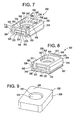
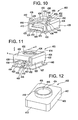
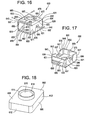
- FIGURES 1-3 A cage nut assembly 100 which is in accordance with a first embodiment of the present invention is shown in FIGURES 1-3 ; a cage nut assembly 200 which is in accordance with a second embodiment of the present invention is shown in FIGURES 4-6 ; a cage nut assembly 300 which is in accordance with a third embodiment of the present invention is shown in FIGURES 7-9 ; a cage nut assembly 400 which is in accordance with a fourth embodiment of the present invention is shown in FIGURES 10-12 ; a cage nut assembly 500 which is in accordance with a fifth embodiment of the present invention is shown in FIGURES 13-15 ; a cage nut assembly 600 which is in accordance with a sixth embodiment of the present invention is shown in FIGURES 16-18 ; and a cage nut assembly 700 which is in accordance with a seventh embodiment of the present invention is shown in FIGURES 19-21 .
- FIGURES 1-3 illustrate a cage nut assembly 100 which is in accordance with a second embodiment of the present invention.
- the cage nut assembly 100 includes a nut member 102 and a cage member 104.
- the nut member 102 is best illustrated in FIGURE 3 and includes a rectangular block 106 having a generally planar upper surface 108, a generally planar lower surface 110 and sidewalls 112 which connect the upper and lower surfaces 108, 110.
- the nut member 102 also includes a cylindrical member 114 which extends outwardly from the upper surface 108 of the nut member 102.
- the cylindrical member 114 is preferably in the form of a right circular cylinder.
- An aperture 116 extends through the nut member 102 from the block 106 into the cylindrical member 114.
- the aperture 116 may be closed at the lower surface 110 of the block 106 or it may extend all the way through the block 106.
- the aperture 116 defines an aperture wall 118 which is preferably threaded and is capable of receiving a bolt or screw (not shown) to be attached thereto.
- the cage member 104 is best illustrated in FIGURES 1 and 2 .
- the cage member 104 is used for encaging the nut member 102. Prior to encaging the nut member 102, the cage member 104 has generally planar upper and lower surfaces 120, 122.
- the cage member 104 includes a base portion 124 and bendable first and second arm portions 126, 128 extending from opposite ends of the base portion 124.
- the first and second arm portions 126, 128 are preferably integrally formed with the base portion 124.
- An aperture 130 is provided through the base portion 124 of the cage member 104 and the first and second arms 126, 128 have generally semicircular cutouts 132, 134 at their free ends 136, 138.
- the first and second arms 126,128 have dimples 140,142 provided on the lower surface 122 thereof which are formed from a stamping process and which extend outwardly from the lower surface 122 thereof.
- the dimples 140, 142 are provided between the semicircular cutouts 132, 134 and the edges 144, 146 of the arms 126, 128.
- the first and second arms 126, 128 have half-dimples 148, 150 provided on the lower surface 122 thereof at the free ends 136, 138 of the arms 126, 128.
- the half-dimples 148, 150 are formed from a stamping process and extend outwardly from the lower surface 122 of the arms 126, 128.
- the half-dimples 148, 150 are provided between the semicircular cutouts 132, 134 and the edges 152,154 of the arms 126, 128.
- the cylindrical member 114 of the nut member 102 is positioned through the aperture 130 of the cage member 104 such that the upper surface 108 of the nut member 102 is abutted against the upper surface 120 of the base portion 124 of the cage member 104.
- the first and second arms 126, 128 are then bent around opposite sidewalls 110 of the nut member 102 and onto the lower surface 110 of the nut member 102 to form the cage nut assembly 100.
- the cage member 104 effectively encages the nut member 102.
- the cage member 104 and the aperture 130 are sized so that the nut member 102 has a limited range of movement in at least one dimension, and preferably in two dimensions, for example the "X" and "Y" axes as illustrated in FIGURE 2 .
- the circular cutout 156 is provided in the cage member 104 to allow access to the aperture 116 of the nut member 102 through the lower surface 110 thereof, within the range of movement of the nut member 102.
- the cage nut assembly 100 must then be attached to a mating surface 157.
- the cage nut assembly 100 is positioned on the mating surface 157 such that the dimples 140, 142, 148, 150 are in contact with the mating surface 157.
- the cage nut assembly 100 is then welded to the mating surface 157 with the assistance of the dimples 540, 542.
- the free-ends 136, 138 are welded together to form a welded seam 158.
- the half-dimples 148, 150 also assist in the welding of the cage nut assembly 100 to the mating surface 157 and are welded together to form a welded dimple 160.
- FIGURES 4-6 illustrate a cage nut assembly 200 which is in accordance with a second embodiment of the present invention.
- the cage nut assembly 200 includes a nut member 202 and a cage member 204.
- the nut member 202 is best illustrated in FIGURE 6 and includes a rectangular block 206 having a generally planar upper surface 208, a generally planar lower surface 210 and sidewalls 212 which connect the upper and lower surfaces 208, 210.
- the nut member 202 also includes a cylindrical member 214 which extends outwardly from the upper surface 208 of the nut member 202.
- the cylindrical member 214 is preferably in the form of a right circular cylinder.
- An aperture 216 extends through the nut member 202 from the block 206 into the cylindrical member 214.
- the aperture 216 maybe closed at the lower surface 210 of the block 206 or it may extend all the way through the block 206.
- the aperture 216 defines an aperture wall 218 which is preferably threaded and is capable of receiving a bolt or screw (now shown) to be attached thereto.
- the cage member 204 is best illustrated in FIGURES 4 and 5 .
- the cage member 204 is used for encaging the nut member 202. Prior to encaging the nut member 202, the cage member 204 has generally planar upper and lower surfaces 220, 222.
- the cage member 204 includes a base portion 224 and bendable first and second arm portions 226, 228 extending from opposite ends of the base portion 224. The first and second arm portions 226, 228 are preferably integrally formed with the base portion 224.
- An aperture 230 is provided through the base portion 224 of the cage member 204 and the first and second arms 226, 228 have generally semicircular cutouts 232, 234 at their free ends 236, 238.
- the first and second arms 226, 228 have dimples 240, 242 provided on the lower surface 222 thereof which are formed from a stamping process and which extend outwardly from the lower surface 222 thereof.
- the dimples 240, 242 are provided proximate to the semicircular cutouts 232, 234 and are provided equidistantly between the edges 244, 246 and the edges 252, 254 of the arms 226, 228.
- the first and second arms 226, 228 have half-dimples 248a, 248b; 250a, 250b provided on the lower surface 222 thereof at the free ends 236, 238 of the arms 236, 238.
- the half-dimples 248a, 248b; 250a, 250b are formed from a stamping process and extend outwardly from the lower surface 222 of the arms 226, 228.
- the half-dimples 248a, 250a are provided between the semicircular cutouts 232, 234 and the edges 244, 246 of the arms 226, 228.
- the half-dimples 248b, 250b are provided between the semicircular cutouts 232, 234 and the edges 252, 254 of the arms 226, 228.
- the cylindrical member 214 of the nut member 202 is positioned through the aperture 230 of the cage member 204 such that the upper surface 208 of the nut member 202 is abutted against the upper surface 220 of the base portion 224 of the cage member 204.
- the first and second arms 226, 228 are then bent around opposite sidewalls 210 of the nut member 202 and onto the lower surface 210 of the nut member 202 to form the cage nut assembly 200.
- the free ends 236,238 of the arms 226, 228 then abut against one another such that the half-dimples 148a, 150a abut against one another, the half-dimples 148b, 150b abut against one another, and the semicircular cutouts 232, 234 are in communication with one another to form a circular cutout 256.
- the cage member 204 effectively encages the nut member 202.
- the cage member 204 and the aperture 230 are sized so that the nut member 202 has a limited range of movement in at least one dimension, and preferably in two dimensions, for example the "X" and "Y" axes as illustrated in FIGURE 4 .
- the circular cutout 256 is provided in the cage member 204 to allow access to the aperture 216 of the nut member 202 through the lower surface 210 thereof, within the range of movement of the nut member 202.
- the cage nut assembly 200 must then be attached to a mating surface 257.
- the cage nut assembly 200 is positioned on the mating surface 257 such that the dimples 240, 242, 248a, 248b, 250a, 250b are in contact with the mating surface 257.
- the cage nut assembly 200 is then welded to the mating surface 257 with the assistance of the dimples 240, 242. During the welding, the free-ends 236, 238 are welded together to form a welded seam 258.
- the half dimples 248a, 250a; 248b, 250b also assist in the welding of the cage nut assembly 200 to the mating surface 257 and the half-dimples 248a, 250a are welded together to form a welded dimple 260a and the half-dimples 248b, 250b are welded together to form a welded dimple 260b.
- FIGURES 7-9 illustrate a cage nut assembly 300 which is in accordance with a second embodiment of the present invention.
- the cage nut assembly 300 includes a nut member 302 and a cage member 304.
- the nut member 302 is best illustrated in FIGURE 9 and includes a rectangular block 306 having a generally planar upper surface 308, a generally planar lower surface 310 and sidewalls 312 which connect the upper and lower surfaces 308, 310.
- An aperture 316 extends through the block 306 of the nut member 302.
- the aperture 316 may be closed at the lower surface 310 of the block 306 or it may extend all the way through the block 306.
- the aperture 316 defines an aperture wall 318 which is preferably threaded and is capable of receiving a bolt or screw (now shown) to be attached thereto.
- the cage member 304 is best illustrated in FIGURES 7 and 8 .
- the cage member 304 is used for encaging the nut member 302. Prior to encaging the nut member 302, the cage member 304 has generally upper and lower surfaces 320, 322.
- the cage member 304 includes a base portion 324 and bendable first and second arm portions 326, 328 extending from opposite ends of the base portion 324.
- the first and second arm portions 326, 328 are preferably integrally formed with the base portion 324.
- the cage member 304 further includes a pair of L-shaped flanges 362, 364 which extend from opposite ends of the base portion 324, but not the opposite ends from which the arm portions 326, 328 extend from the base portion 324.
- the L-shaped flange 362 has a first portion 366 which extends perpendicularly upwardly from the base portion 324 proximate to the second arm portion 328, and a second portion 368 which extends perpendicularly from the first portion 366 toward the first arm portion 326.
- the L-shaped flange 364 has a first portion 370 which extends perpendicularly outwardly from the base portion 324 proximate to the first arm portion 326, and a second portion 372 which extends perpendicularly from the first portion 370 toward the second arm portion 328.
- the L-shaped flange 364 is bendable.
- the L-shaped flanges 362, 364 are preferably integrally formed with the base portion 324 of the cage member 304.
- An aperture 330 is provided through the base portion 324 of the cage member 304 and the first and second arms 326, 328 have generally semicircular cutouts 332, 334 at their free ends 336, 338.
- the first and second arms 326, 328 have dimples 340, 342 provided on the lower surface 322 thereof which are formed from a stamping process and which extend outwardly from the lower surface 322 thereof.
- the dimples 340, 342 are provided between the semicircular cutouts 332, 334 and the edges 344, 346 of the arms 326, 328.
- the first and second arms 326, 328 have half-dimples 348, 350 provided on the lower ssurface 322 thereof at the free ends 336, 338 of the arms 326, 328.
- the half-dimples 348, 350 are formed from a stamping process and extend outwardly from the lower surface 322 of the arms 326, 328.
- the half-dimples 348, 350 are provided between the semicircular cutouts 332, 334 and the edges 352, 354 of the arms 326, 328.
- first and second arms 326, 328 are bent such that the free ends 336, 338 of the arms 326, 328 abut against one another such that the half-dimples 348, 350 abut against one another and the semicircular cutouts 332, 334 are in communication with one another to form a circular cutout 356.
- the nut member 302 is then slid into the cage member 304 at the end of the cage member 304 where the L-shaped flange 364 is provided for such that the upper surface 108 of the nut member 302 is facing the upper surface 320 of the base portion 324 of the cage member 304.
- the L-shaped flange 362 prevents the nut member 302 from sliding out of the cage member 302.
- the L-shaped flange 364 is bent to prevent the nut member 302 from sliding out of the cage member 302, thus effectively encaging the nut member 302 within the cage member 304 and forming the cage nut assembly 300, as best illustrated in FIGURE 7 .
- the cage member 304 is sized so that the nut member 302 has a limited range of movement in at least one dimension, and preferably in two dimensions, for example the "X" and "Y" axes as illustrated in FIGURE 7 .
- the circular cutout 356 is provided in the cage member 304 to allow access to the aperture 316 of the nut member 302 through the lower surface 310 thereof, within the range of movement of the nut member 302.
- the cage nut assembly 300 must then be attached to a mating surface 357.
- the cage nut assembly 300 is positioned on the mating surface 357 such that the dimples 340, 342, 348, 350 are in contact with the mating surface 357.
- the cage nut assembly 300 is then welded to the mating surface 357 with the assistance of the dimples 340, 342.
- the free-ends 336, 338 are welded together to form a welded seam 358.
- the half-dimples 348, 350 also assist in the welding of the cage nut assembly 300 to the mating surface 357 and are welded together to form a welded dimple 360.
- cage nut assembly 300 could also be formed to have four dimples, similar to that disclosed in the second embodiment of the cage nut assembly 200, rather than three dimples.
- FIGURES 10-12 illustrate a cage nut assembly 400 which is in accordance with a fourth embodiment of the present invention.
- the cage nut assembly 400 includes a nut member 402 and a cage member 404.
- the nut member 402 is best illustrated in FIGURE 12 and includes a rectangular block 406 having a generally planar upper surface 408, a generally planar lower surface 410 and sidewalls 412 which connect the upper and lower surfaces 408, 410.
- the nut member 402 also includes a cylindrical member 414 which extends outwardly from the upper surface 408 of the nut member 402.
- the cylindrical member 414 is preferably in the form of a right circular cylinder.
- An aperture 416 extends through the nut member 402 from the block 406 into the cylindrical member 414.
- the aperture 416 may be closed at the lower surface 410 of the block 406 or it may extend all the way through the block 406.
- the aperture 416 defines an aperture wall 418 which is preferably threaded and is capable of receiving a bolt or screw (now shown) to be attached thereto.
- the cage member 404 is best illustrated in FIGURES 10-11 .
- the cage member 404 is used for encaging the nut member 402. Prior to encaging the nut member 402, the cage member 404 has generally planar upper and lower surfaces 420, 422.
- the cage member 404 includes a base portion 424 and bendable first and second arm portions 426, 428 extending from opposite ends of the base portion 424.
- the first and second arm portions 426, 428 are preferably integrally formed with the base portion 424.
- the cage member 404 further includes a pair of flanges 462, 464 which extend from opposite ends of the base portion 424, but not the opposite ends from which the arm portions 426, 428 extend from the base portion 424.
- the flange 462 extends perpendicularly upwardly from the base portion 424 and extends substantially between the arm portions 426, 428.
- the flange 464 is L-shaped such that it has a first portion 470 which extends perpendicularly outwardly from the base portion 424 proximate to the first arm portion 426, and a second portion 472 which extends perpendicularly from the first portion 470 toward the second arm portion 428.
- the L-shaped flange 464 is bendable.
- the flanges 462, 464 are preferably integrally formed with the base portion 424 of the cage member 404.
- An aperture 430 is provided through the base portion 424 of the cage member 404 and the first and second arms 426, 428 have generally semicircular cutouts 432, 434 at their free ends 436, 438.
- the first and second arms 426, 428 have tabs 440, 442 provided on the lower surface 422 thereof which extend outwardly from the lower surface 422 thereof.
- the tabs 440, 442 are provided between the semicircular cutouts 432,434 and the edges 444,446 of the arms 426, 428.
- the first and second arms 426, 428 have half-tabs 448, 450 provided on the lower surface 422 thereof at the free ends 436, 438 of the arms 426, 428.
- the half-tabs 448, 450 extend outwardly from the lower surface 422 of the arms 426, 428.
- the half-tabs 448, 450 are provided between the semicircular cutouts 432, 434 and the edge 452, 454 of the arms 426, 428.
- the cylindrical member 414 of the nut member 402 is positioned through the aperture 430 of the cage member 404 such that the upper surface 408 of the nut member 402 is abutted against the upper surface 420 of the base portion 424 of the cage member 404.
- the first and second arms 426, 428 are bended around opposite sidewalls 412 of the nut member 402 and onto the lower surface 410 of the nut member 402 to form the cage nut assembly 400.
- the free ends 436, 438 of the arms 426, 428 then abut against one another such that the half-tabs 448, 450 abut against one another and the semicircular cutouts 432, 434 are in communication with one another to form a circular cutout 456.
- the tabs 440, 442 extend outwardly from the lower surface 422 of the cage member 404 at the bend of the first and second arms 426, 428 around the lower surface 410 of the nut member 402 such that the tabs 440, 442 extend in an opposite direction as does the cylindrical member 414 of the nut member 402.
- the cage member 404 and the aperture 430 are sized so that the nut member 402 has a limited range of movement in at least one dimension, and preferably in three dimensions, for example the "X", “Y” and “Z” axes as illustrated in FIGURE 11 .
- the circular cutout 456 is provided in the cage member 404 to allow access to the aperture 416 of the nut member 402 through the lower surface 410 thereof, within the range of movement of the nut member 402.
- the cage nut assembly 400 must then be attached to a mating surface 457.
- the cage nut assembly 400 is positioned on the mating surface 457 such that the tabs 440, 442, 448, 450 are in contact with the mating surface 457.
- the cage nut assembly 400 is then welded to the mating surface 457 with the assistance of the tabs 440, 442.
- the free-ends 436, 438 are welded together to form a welded seam 458.
- the half-tabs 448, 450 also assist in the welding of the cage nut assembly 400 to the mating surface 457 and are welded together to form a welded tab 460.
- the nut member 402 could be formed without the cylindrical member 414 and the cage member 404 sized so that the nut member 402 has a limited range of movement in at least one direction, and preferably in two dimensions, for example the "X" and "Y" axes as illustrated in FIGURE 11 .
- cage nut assembly 400 could also be formed to have four tabs, similar to that disclosed in the second embodiment of the cage nut assembly 200, except with dimples, rather than three tabs.
- FIGURES 13-15 illustrate a cage nut assembly 500 which is in accordance with a fifth embodiment of the present invention.
- the cage nut assembly 500 includes a nut member 502 and a cage member 504.
- the nut member 502 is best illustrated in FIGURE 15 and includes a rectangular block 506 having a generally planar upper surface 508, a generally planar lower surface (not shown) and sidewalls 512 which connect the upper and lower surfaces 508.
- the nut member 502 also includes a cylindrical member 514 which extends outwardly from the upper surface 508 of the nut member 502.
- the cylindrical member 514 is preferably in the form of a right circular cylinder.
- An aperture 516 extends through the nut member 502 from the block 506 into the cylindrical member 514.
- the aperture 516 may be closed at the lower surface 510 of the block 506 or it may extend all the way through the block 506.
- the aperture 516 defines an aperture wall 518 which is preferably threaded and is capable of receiving a bolt or screw (now shown) to be attached thereto.
- the cage member 504 is best illustrated in FIGURES 13 and 14 .
- the cage member 504 is used for encaging the nut 502. Prior to encaging the nut member 502, the cage member 504 is formed such that it has a first sidewall 521 having top and bottom edges 523, 525 and first and second side ends 527, 529.
- the cage member 504 further is formed to include a second side wall 531 having top and bottom edges 533, 535 and first and second side ends 537, 539.
- the second side wall 531 is integrally formed with the first side wall 521 such that the first side end 537 of the second side wall 531 is equivalent to the second side end 529 of the first side wall 521.
- the second side wall 531 extends perpendicularly along the "X" axis, as illustrated in FIGURE 13 , from the first side wall 521.
- the bottom edge 535 of the second side wall 531 is provided in the same plane as the bottom edge 525 of the first side wall 521; the top edge 533 of the second side wall 531 is provided in a different plane than the top edge 535 of the first side wall 521.
- the cage member 504 further is formed to include a third side wall 541 having top and bottom edges 543, 545 and first and second side ends 547, 549.
- the third side wall 541 is integrally formed with the second side wall 531 such that the first side end 547 of the third side wall 541 is equivalent to the second side end 539 of the second side wall 531.
- the third side wall 541 extends perpendicularly along the "Y" axis, as illustrated in FIGURE 13 , from the second side wall 531 such that the third side wall 541 is parallel to the first side wall 521.
- the top and bottom edges 543, 545 of the third side wall 541 are provided in the same plane as the top and bottom edges 523, 525 of the first side wall 521.
- the cage member 504 further is formed to include a fourth side wall 551 having top and bottom edges 553, 555 and first and second side ends 557, 559.
- the fourth side wall 551 is integrally formed with the third side wall 541 such that the first side end 557 of the fourth side wall 551 is equivalent to the second side end 549 of the third side wall 541.
- the fourth side wall 551 extends perpendicularly along the "X" axis, as illustrated in FIGURE 13 , from the third side wall 541 such that the fourth side wall 551 is parallel to the second side wall 531.
- the top and bottom edges 553, 555 of the fourth side wall 551 are provided in the same plane as the top and bottom edges 523, 525 of the first side wall 521.
- the second side end 559 of the fourth side wall 551 is also formed with a dove-tail pocket 561 provided therein.
- the cage member 504 further includes a fifth side wall 563 having top and bottom edges 565, 567 and first and second side ends 569, 571.
- the fifth side wall 563 is integrally formed with the first side wall 521 such that the second side end 571 of the fifth side wall 563 is equivalent to the first side end 527 of the first side wall 521.
- the fifth side wall 563 extends perpendicularly along the "X" axis, as illustrated in FIGURE 13 , from the first side wall 521 such that the fifth side wall 563 is parallel to the second side wall 531.
- the top and bottom edges 565, 567 of the fifth side wall 563 are provided in the same plane as the top and bottom edges 523, 525 of the first side wall 521.
- the first side end 569 of the fifth side wall 563 is also formed with a dove-tail extension 573 provided thereon.
- the dove-tail extension 573 is inserted into the dove-tail pocket 561 in order to lock the fourth side wall 551 to the fifth side wall 563 such that the second side end 559 of the fourth side wall 551 abuts against the first side end 569 of the fifth side wall 563.
- a seam 575 is provided between the second side end 559 of the fourth side wall 551 and the first side end-569 of the fifth side wall 563.
- a tab 540 is provided on the bottom edge 525 of the first side wall 521 proximate to the connection of the first and second side walls 521, 531.
- a tab 542 is provided on the bottom edge 545 of the third side wall 541 proximate to the connection of the second and third side walls 531, 541.
- a half tab 548 is provided on the bottom edge 555 of the fourth side wall 551 proximate to the connection of the fourth and fifth side walls 551, 563.
- a half tab 550 is provided on the bottom edge 567 of the fifth side wall 563 proximate to the connection of the fourth and fifth side walls 551, 563. The half tabs 548, 550 abut against one another such that the seam 575 is provided therebetween.
- a first flap 577 extends from the top edge 523 of the first side wall 521 and has a generally semicircular cutout 579 at its free end 581.
- the first flap 577 is bendable.
- a second flap 583 extends from the top edge 543 of the third side wall 541 and has a generally semicircular cutout 585 at its free end 587.
- the second flap 583 is bendable.
- the first and second flaps 577,583 are bent toward one another such that the free ends 581, 587 abut against one another and such that the semicircular cutouts 579, 585 are in communication with one another to form a circular cutout 589.
- a window 591 is provided between the first, second and third side walls 521, 531, 541 and the flaps 577, 583.
- a flange 593 covers a portion of the window 591 and extends from the connection of the second and third side walls 531, 541. The flange 593 is bendable.
- the first side wall 521 also has a fold-out arm 595 provided thereon which is integrally formed with the first side wall 521 and is positioned equidistant from the first and second side ends 527, 529 of the first side wall 521.
- the fold-out arm 595 is also bendable.
- the third side wall 541 also has a fold-out arm 597 provided thereon which is integrally formed with the third side wall 541 and is positioned equidistantly from the first and second side ends 547, 549 of the third side wall 541.
- the fold out-arm 597 is further bendable.
- nut member 502 is positioned between the sidewalls 521, 531, 541,551, 563 of the cage member 504 such that the cylindrical member 514 of the nut member 502 is positioned through the circular cutout 589 of the cage member 504.
- the fold-out arms 595, 597 are then bended to abut against the lower surface 510 of the nut member 502 to form the cage nut assembly 500, such that the cage member 504 effectively encages the nut member 502.
- the cage member 504 and the circular cutout 589 are sized so that the nut member 502 has a limited range of movement in at least one dimension, and preferably in two dimensions, for example the "X" and "Y" axes as illustrated in FIGURE 13 .
- the cage nut assembly 500 must then be attached to a mating surface 557.
- the cage nut assembly 500 is positioned on the mating surface 557 such that the tabs 540, 542, 548, 550 are in contact with the mating surface 557.
- the cage nut assembly 500 is then welded to the mating surface 557 with the assistance of the tabs 540, 542.
- the fourth and fifth sidewalls 551, 563 are welded together along the seam 575.
- the half-tabs 548, 550 also assist in the welding of the cage nut assembly 500 to the mating surface 557 and are welded together to form a welded tab 560.
- the window 591 acts as a nut member removal window for servicing the nut member 502 if need be.
- the flange 593 acts to help retain the nut member 502 within the cage member 504, but also can be bended outwardly to provide access to the nut member 502 if the nut member 502 needs to be serviced.
- the nut member 502 could be formed without the cylindrical member 514 and the cage member 504 sized so that the nut member 502 has a limited range of movement in at least one direction, and preferably in two dimensions, for example the "X" and "Y" axes as illustrated in FIGURE 13 .
- FIGURES 16-18 illustrate a cage nut assembly 600 which is in accordance with a sixth embodiment of the present invention.
- the cage nut assembly 600 includes a nut member 602 and a cage member 604.
- the nut member 602 is best illustrated in FIGURE 18 and includes a rectangular block 606 having a generally planar upper surface 608, a generally planar lower surface 610 and sidewalls 612 which connect the upper and lower surfaces 608, 610.
- the nut member 602 also includes a cylindrical member 614 which extends outwardly from the upper surface 608 of the nut member 602.
- the cylindrical member 614 is preferably in the form of a right circular cylinder.
- An aperture 616 extends through the nut member 602 from the block 606 into the cylindrical member 614.
- the aperture 616 may be closed at the lower surface 610 of the block 606 or it may extend all the way through the block 606.
- the aperture 616 defines an aperture wall 618 which is preferably threaded and is capable of receiving a bolt or screw (now shown) to be attached thereto.
- the cage member 604 is best illustrated in FIGURES 16-17 .
- the cage member 604 is used for encaging the nut 602. Prior to encaging the nut member 602, the cage member 604 is formed such that it has a first sidewall 621 having top and bottom edges 623, 625 and first and second side ends 627, 629.
- the cage member 604 further is formed to include a second side wall 631 having top and bottom edges 633, 635 and first and second side ends 637, 639.
- the second side wall 631 is integrally formed with the first side wall 621 such that the first side end 637 of the second side wall 631 is equivalent to the second side end 629 of the first side wall 621.
- the second side wall 631 extends perpendicularly along the "X" axis, as illustrated in FIGURE 16 , from the first side wall 621.
- the bottom edge 636 of the second side wall 631 is provided in the same plane as the bottom edge 625 of the first side wall 621; the top edge 633 of the second side wall 631 is provided in a different plane than the top edge 623 of the first side wall 621.
- the cage member 604 further is formed to include a third side wall 641 having top and bottom edges 643, 645 and first and second side ends 647, 649.
- the third side wall 641 is integrally formed with the second side wall 631 such that the first side end 647 of the third side wall 641 is equivalent to the second side end 639 of the second side wall 631.
- the third side wall 641 extends perpendicularly along the "Y" axis, as illustrated in FIGURE 16 , from the second side wall 631 such that the third side wall 641 is parallel to the first side wall 621.
- the top and bottom edges 643, 645 of the third side wall 641 are provided in the same plane as the top and bottom edges 623, 625 of the first side wall 621.
- the cage member 604 further is formed to include a fourth side wall 651 having top and bottom edges 653, 655 and first and second side ends 657, 659.
- the fourth side wall 651 is integrally formed with the third side wall 641 such that the first side end 657 of the fourth side wall 651 is equivalent to the second side end 649 of the third side wall 641.
- the fourth side wall 651 extends perpendicularly along the "X" axis, as illustrated in FIGURE 16 , from the third side wall 641 such that the fourth side wall 651 is parallel to the second side wall 631.
- the top and bottom edges 653, 655 of the fourth side wall 651 are provided in the same plane as the top and bottom edges 623, 625 of the first side wall 621.
- the second side end 659 of the fourth side wall 651 is also formed with a dove-tail pocket 661 provided therein.
- the cage member 604 further includes a fifth side wall 663 having top and bottom edges 665, 667 and first and second side ends 669, 671.
- the fifth side wall 663 is integrally formed with the first side wall 621 such that the second side end 671 of the fifth side wall 663 is equivalent to the first side end 627 of the first side wall 621.
- the fifth side wall 663 extends perpendicularly along the "X" axis, as illustrated in FIGURE 16 , from the first side wall 621 such that the fifth side wall 663 is parallel to the second side wall 631.
- the top and bottom edges 665, 667 of the fifth side wall 663 are provided in the same plane as the top and bottom edges 623, 625 of the first side wall 621.
- the first side end 669 of the fifth side wall 663 is also formed with a dove-tail extension 673 provided thereon.
- the dove-tail extension 673 is inserted into the dove-tail pocket 661 in order to lock the fourth side wall 651 to the fifth side wall 663 such that the second side end 659 of the fourth side wall 651 abuts against the first side end 669 of the fifth side wall 663.
- a seam 675 is provided between the second side end 659 of the fourth side wall 651 and the first side end 669 of the fifth side wall 663.
- a tab 640 is provided on the bottom edge 625 of the first side wall 621 proximate to the connection of the first and second side walls 621, 631.
- a tab 642 is provided on the bottom edge 645 of the third side wall 641 proximate to the connection of the second and third side walls 631, 641.
- a tab 699 is provided on the bottom edge 667 of the fifth side wall 663 proximate to the connection of the fourth and fifth side walls 651, 663. The tab 699 abuts against the bottom edge 655 of the fourth side wall 651 proximate to the connection of the fourth and fifth side walls 651, 663 such that the seam 675 is provided therebetween.
- a first flap 677 extends from the top edge 623 of the first side wall 621 and has a generally semicircular cutout 679 at its free end 681.
- the first flap 677 is bendable.
- a second flap 683 extends from the top edge 643 of the third side wall 641 and has a generally semicircular cutout 685 at its free end 687.
- the second flap 683 is bendable.
- the first and second flaps 677, 683 are bent toward one another such that the free ends 681, 687 abut against one another and such that the semicircular cutouts 679, 685 are in communication with one another to form a circular cutout 689.
- a window 691 is provided between the first, second and third side walls 621, 631, 641 and the flaps 677, 683.
- a flange 693 covers a portion of the window 691 and extends from the connection of the second and third side walls 631, 641. The flange 693 is bendable.
- the first side wall 621 also has a fold-out arm 695 provided thereon which is integrally formed with the first side wall 621 and is positioned equidistant from the first and second side ends 627, 629 of the first side wall 621.
- the fold-out arm 695 is also bendable.
- the third side wall 641 also has a fold-out arm 697 provided thereon which is integrally formed with the third side wall 641 and is positioned equidistantly from the first and second side ends 647, 649 of the third side wall 641.
- the fold out arm 697 is further bendable.
- nut member 602 is positioned between the sidewalls 621, 631, 641, 651, 663 of the cage member 604 such that the cylindrical member 614 of the nut member 602 is positioned through the circular cutout 689 of the cage member 604.
- the fold-out arms 695, 697 are then bended to abut against the lower surface 610 of the nut member 602 to form the cage nut assembly 600, such that the cage member 604 effectively encages the nut member 602.
- the cage member 604 and the circular cutout 689 are sized so that the nut member 602 has a limited range of movement in at least one dimension, and preferably in two dimensions, for example the "X" and "Y" axes as illustrated in FIGURE 16 .
- the cage nut assembly 600 must then be attached to a mating surface 657.
- the cage nut assembly 600 is positioned on the mating surface 657 such that the tabs 640, 642, 699 are in contact with the mating surface 657.
- the cage nut assembly 600 is then welded to the mating surface 657 with the assistance of the tabs 640, 642.
- the fourth and fifth sidewalls 651, 663 are welded together along the seam 675.
- the tab 699 also assists in the welding of the cage nut assembly 600 to the mating surface 657 and is welded to the bottom surface 655 of the fourth side wall 651 to form a welded tab 660.
- the window 691 acts as a nut member removal window for servicing the nut member 602 if need be.
- the flange 693 acts to help retain the nut member 602 within-the cage member 604, but also can be bended outwardly to provide access to the nut member 602 if the nut member 602 needs to be serviced.
- the nut member 602 could be formed without the cylindrical member 614 and the cage member 604 sized so that the nut member 602 has a limited range of movement in at least one direction, and preferably in two dimensions, for example the "X" and "Y" axes as illustrated in FIGURE 16 .
- FIGURES 19-21 illustrate a cage nut assembly 700 which is in accordance with a seventh embodiment of the present invention.
- the cage nut assembly 700 includes a nut member 702 and a cage member 704.
- the nut member 702 is best illustrated in FIGURE 21 and includes a rectangular block 706 having a generally planar upper surface 708, a generally planar lower surface (not shown) and sidewalls 712 which connect the upper and lower surfaces 708.
- An aperture 716 extends through the block 706 of the nut member 702.
- the aperture 716 may be closed at the lower surface 710 of the block 706 or it may extend all the way through the block 706.
- the aperture 716 defines an aperture wall 718 which is preferably threaded and is capable of receiving a bolt or screw (now shown) to be attached thereto.
- the cage member 704 is best illustrated in FIGURES 19-20 .
- the cage member 704 is used for encaging the nut 702. Prior to encaging the nut member 702, the cage member 704 is formed such that it has a first sidewall 721 having top and bottom edges 723, 725 and first and second sides 727, 729.
- the cage member 704 further is formed to include a second side wall 731 having top and bottom edges 733, 735 and first and second side ends 737, 739.
- the second side wall 731 is integrally formed with the first side wall 721 such that the first side end 737 of the -second side wall 731 is equivalent to the second side end 729 of the first side wall 721.
- the second side wall 731 extends perpendicularly along the "X" axis, as illustrated in FIGURE 21 , from the first side wall 721.
- the bottom edge 735 of the second side wall 731 is provided in the same plane as the bottom edge 725 of the first side wall 721; the top edge 733 of the second side wall 731 is provided in a different plane than the top edge 722 of the first side wall 721.
- the cage member 704 further is formed to include a third side wall 741 having top and bottom edges 743, 745 and first and second side ends 747, 749.
- the third side wall 741 is integrally formed with the second side wall 731 such that the first side end 747 of the third side wall 741 is equivalent to the second side end 739 of the second side wall 731.
- the third side wall 741 extends perpendicularly along the "Y" axis, as illustrated in FIGURE 19 , from the second side wall 731 such that the third side wall 741 is parallel to the first side wall 721.
- the top and bottom edges 743, 745 of the third side wall 741 are provided in the same plane as the top and bottom edges 723, 725 of the first side wall 721.
- the cage member 704 further is formed to include a fourth side wall 751 having top and bottom edges 753, 755 and first and second side ends 757, 759.
- the fourth side wall 751 is integrally formed with the third side wall 741 such that the first side end 757 of the fourth side wall 751 is equivalent to the second side end 749 of the third side wall 741.
- the fourth side wall 751 extends perpendicularly along the "X" axis, as illustrated in FIGURE 19 , from the third side wall 741 such that the fourth side wall 751 is parallel to the second side wall 731.
- the top and bottom edges 753,755 of the fourth side wall 751 are provided in the same plane as the top and bottom edges 723, 725 of the first side wall 721.
- the second side end 759 of the fourth side wall 751 is also formed with a dove-tail pocket 761 provided therein.
- the eage member 704 further includes a fifth side wall 763 having top and bottom edges 765, 767 and first and second side-ends 769, 771.
- The-fifth-side-wall 763 is integrally formed with the first side wall 721 such that the second side end 771 of the fifth side wall 763 is equivalent to the first side end 727 of the first side wall 721.
- the fifth side wall 763 extends perpendicularly along the "X" axis, as illustrated in FIGURE 19 , from the first side wall 721 such that the fifth side wall 763 is parallel to the second side wall 731.
- the top and bottom edges 765, 767 of the fifth side wall 763 are provided in the same plane as the top and bottom edges 723, 725 of the first side wall 721.
- the first side end 769 of the fifth side wall 763 is also formed with a dove-tail extension 773 provided thereon.
- the dove-tail extension 773 is inserted into the dove-tail pocket 761 in order to lock the fourth side wall 751 to the fifth side wall 763 such that the second side end 759 of the fourth side wall 751 abuts against the first side end 769 of the fifth side wall 763.
- a seam 775 is provided between the second side end 759 of the fourth side wall 751 and the first side end 769 of the fifth side wall 763.
- a tab 740 is provided on the bottom edge 725 of the first side wall 721 proximate to the connection of the first and second side walls 721, 731.
- a tab 742 is provided on the bottom edge 745 of the third side wall 741 proximate to the connection of the second and third side walls 731, 741.
- a half tab 748 is provided on the bottom edge 755 of the fourth side wall 751 proximate to the connection of the fourth and fifth side walls 751, 763.
- a half tab 750 is provided on the bottom edge 767 of the fifth side wall 763 proximate to the connection of the fourth and fifth side walls 751, 763. The half tabs 748, 750 abut against one another such that the seam 775 is provided therebetween.
- a first flap 777 extends from the top edge 723 of the first side wall 721 and has a generally semicircular cutout 779 at its free end 781.
- the first flap 777 is bendable.
- a second flap 783 extends from the top edge 743 of the third side wall 741 and has a generally semicircular cutout 758 at its free end 787.
- the second flap 783 is bendable.
- the first and second-flaps 777, 783 are bent toward one another such that the free ends 781, 787 abut against one another and such that the semicircular cutouts 779, 785 are in communication with one another to form a circular cutout 789.
- a third flap 778 extends from the bottom edge 725 of the first side wall 721 and has a generally semicircular cutout780 at its free end 782.
- the third flap 778 is bendable.
- a fourth flap 784 extends from the bottom edge 745 of the third side wall 741 and has a generally semicircular cutout 786 at its free end 788.
- the fourth flap 784 is bendable.
- the third and fourth flaps 778, 784 are bent toward one another such that the free ends 782, 788 abut against one another and such that the semicircular cutouts 780, 786 are in communication with one another to form a circular cutout 790.
- a window 791 is provided between the first, second and third side wall 721, 731, 741 and the flaps 777, 783, 778, 784.
- a flange 793 covers a portion of the window 791 and extends from the connection of the second and third side walls 731, 741. The flange 793 is bendable.
- the nut member 702 is slid into the cage member 704 through the window 791 such that the nut member 702 is positioned between the sidewalls 721, 731, 741, 751, 763 and the flaps 777, 783, 778, 784, and such that the aperture 716 of the nut member 718 is accessible through either of the circular cutouts 789, 790.
- the flange 793 is then bended to be positioned parallel with the second side wall 731 in order to cover a portion of the window 791 and to help retain the nut member 702 within the cage member 704.
- the cage member 704 effectively encages the nut member 702 and is sized so that the nut member 702 has a limited range of movement in at least one dimension, and preferably in two dimensions, for example the "X" and "Y" axes as illustrated in FIGURE 19 .
- the cage nut assembly 700 must then be attached to a mating surface 757.
- the cage nut assembly 700 is positioned on the mating surface 757 such that the tabs 740, 742, 748, 750 are in contact with the mating surface 757.
- the cage nut assembly 700 is then welded to the mating surface 757 with the assistance of the tabs 740, 742.
- the fourth and fifth sidewalls 751, 763 are welded together along the seam 775.
- the half-tabs 748, 750 also assist in the welding of the cage nut assembly 700 to the mating surface 757 and are welded together to form a welded tab 760.
- the window 791 acts as a nut member removal window for servicing the nut member 702 if need be.
- the flange 793 can be bended outwardly to provide access to the nut member 702 if the nut member 702 needs to be serviced.
- the welding of the cage nut assemblies 100, 200, 300, 400, 500, 600, 700 to the mating surface 157, 257, 357, 457, 557, 657, 757 provides a 4-sided continuous box, because of the welded seams 158, 258, 358, 458, 558, 658, 758, and the welded dimples and tabs 160, 260, 360, 460, 560, 660, 760, which has improved strength characteristics in comparison to cage nut assemblies of the prior art.
- the cage nut assemblies 100, 200, 300, 400, 500, 600, 700 can be formed with material that is formed with a maximum thickness of 1.8 millimeters whereas the prior art cage nut assemblies were formed with a minimum thickness of 2.0 millimeters.
- the cage nut assemblies 100, 200, 300, 400, 500, 600, 700 provides for at least a 10% decrease in the thickness of the material used to form the cage nut assemblies 100, 200, 300, 400, 500, 600, 700, such that substantial savings in cost are realized in the manufacture of the cage nut assemblies 100, 200, 300, 400, 500, 600, 700.
- FIGURE 22 illustrates a method of attaching the cage member 104, 204, 304, 404, 504 and 704 to the mating surface 157, 257, 357, 457, 557, 757.
- FIGURE 23 illustrates a method of attaching the cage nut assembly 100, 200, 300, 400, 500 and 700 to the mating surface 157, 257, 357, 457, 557, 757.
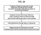
- FIGURE 24 illustrates a method of attaching the cage nut assembly 600 to the mating surface 657.
- each embodiment provides a cage nut assembly 100, 200, 300, 400, 500, 600, 700 which is configured such that it can have a cage member 104, 204, 304, 404, 504, 604, 704 with a relatively thin wall thickness, yet meet torque requirements in a desired application.
- Each embodiment also provides a cage nut assembly 100, 200, 300, 400, 500, 600, 700 which is relatively inexpensive to manufacture but which meets torque requirements in a desired application.
- each embodiment provides a cage nut assembly 100, 200, 300, 400, 500, 600, 700 which can be utilized in any nut application that requires a nut member 102, 202, 302, 402, 502, 602, 702 to have an "X" and "Y" axis adjustability.
Landscapes
- Engineering & Computer Science (AREA)
- General Engineering & Computer Science (AREA)
- Mechanical Engineering (AREA)
- Connection Of Plates (AREA)
- Rolling Contact Bearings (AREA)
- Standing Axle, Rod, Or Tube Structures Coupled By Welding, Adhesion, Or Deposition (AREA)
- Toys (AREA)
- Structures Of Non-Positive Displacement Pumps (AREA)
- Gripping Jigs, Holding Jigs, And Positioning Jigs (AREA)
- Transmission Devices (AREA)
- Dowels (AREA)
- Perforating, Stamping-Out Or Severing By Means Other Than Cutting (AREA)
- Nonmetal Cutting Devices (AREA)
- Polishing Bodies And Polishing Tools (AREA)
- Braking Arrangements (AREA)
- Seats For Vehicles (AREA)
Claims (31)
- Käfigteil (104, 204, 304, 404, 504, 604, 704) der mit einem Mutternteil (102, 202, 302, 402, 502, 602, 702) in Eingriff bringbar ist, die eine Gewindeöffnung (116, 216, 316, 416, 516, 616, 716) aufweist, wodurch eine Käfigmuttern-Baugruppe (100, 200, 300, 400, 500, 600, 700) geschaffen wird, wobei der Käfigteil (104, 204, 304, 404, 504, 604, 704) einen Hauptteil aufweist, der so geformt ist, dass er den Mutternteil (102, 202, 302, 402, 502, 602, 702) als Käfig umschließt und eine darin ausgebildete Öffnung (130, 230, 330, 430, 589, 689, 789) aufweist, wobei die Öffnung (130, 230, 330, 430, 589, 689, 789) so konfiguriert ist, dass sie einen Zugang an die Gewindeöffnung (116, 216. 316, 416, 516, 616, 716) des Mutternteils (102, 202, 302, 402, 502, 602, 702) ermöglicht, wenn der Mutternteil (102, 202, 302, 402, 502, 602, 702) allgemein von dem Käfigteil (104, 204, 304, 404, 504, 604, 704) umschlossen ist, wobei der Käfigteil (104, 204. 304, 404, 504, 604, 704) dadurch gekennzeichnet ist, dass:der Hauptteil eine allgemein ebene Oberfläche und einen verschweißbaren Saum (158, 258, 358, 458, 575, 676, 775) bildet und zumindest einen Vorsprung (140, 142, 160; 240, 242, 260a. 260b; 340, 342, 360; 440, 442, 460; 540, 542, 560; 640. 642, 699; 740, 742, 760) aufweist, der sich von der ebenen Oberfläche aus nach außen erstreckt, wobei der Vorsprung (140, 142, 160; 240, 242, 260a, 260b; 340, 342, 360; 440, 442, 460; 540, 542, 560; 640, 642, 699; 740, 742, 760) so konfiguriert ist, dass der Vorsprung (140, 142, 160; 240, 242, 260a, 260b, 340, 342. 360; 440, 442, 460; 540, 542, 560; 640, 642, 699; 740, 742, 760) mit einer zugehörigen Oberfläche (157, 257, 357, 457, 557, 657, 757) verschweißbar ist, um den Käfigteil (104, 204, 304, 404, 504, 604, 704) mit der zugehörigen Oberfläche (157, 257, 357, 457, 557. 657, 757) zu verschweißen, wobei der Käfigteil (104, 204, 304, 404, 504, 604, 704) so konfiguriert ist, dass er eine Einstellung des Mutternteils in zumindest einer Dimension gegenüber dem Hauptteil des Käfigteil (104. 204, 304, 404, 504, 604, 704) ermöglicht, wenn der Mutternteil (102, 202, 302, 402, 502. 602, 702) von dem Käfigteil (104, 204, 304, 404, 504, 604, 704) umgeben ist.
- Käfigteil (104, 204, 304, 404) nach Anspruch 1, bei dem der Hauptteil einen Basisteil (124, 224, 324, 424) und erste und zweite Armteile (126, 128; 226, 228; 326, 328; 426, 428) aufweist, die sich von dem Basisteil (124, 224, 324, 424) aus erstrecken, wobei der verschweißbare Saum (158, 258, 358, 458) zwischen den ersten und zweiten Armteilen (126, 128; 226, 228; 326, 328; 426, 428) gebildet ist, wobei die ersten und zweiten Armteile (126, 128; 226, 228; 326, 328; 426, 428) die allgemein ebene Oberfläche bilden, wobei der zumindest eine Vorsprung (140, 142, 160; 240, 242, 260a, 260b; 340, 342, 360; 440, 442, 460), der sich von der ebenen Oberfläche aus nach außen erstreckt, auf zumindest einem der ersten und zweiten Armteile (126, 128; 226, 228; 326, 328: 426, 428) vorgesehen ist, wobei der verschweißbare Saum (158, 258, 358, 458) zur Bereitstellung in der Nähe der zugehörigen Oberfläche (157, 257, 357, 457) vorgesehen ist, wobei der Käfigteil (104, 204, 304, 404) so konfiguriert ist, dass er eine Einstellung des Mutternteils (102, 202, 302, 402) in zumindest einer Dimension gegenüber dem Basisteil (124, 224, 324, 424) des Hauptteils des Käfigteils (104, 204, 304, 404) ermöglicht, wenn der Mutternteil (102, 202, 302, 402) käfigförmig von dem Käfigteil (104, 204, 304, 404) umschlossen ist.
- Käfigteil (104, 204, 304, 404) nach Anspruch 1, bei dem der zumindest eine Vorsprung (140, 142, 160; 240, 242, 260a, 260b; 340, 342, 360; 440, 442, 460) benachbart zu dem Saum (158, 258, 358,458) angeordnet ist.
- Käfigteil (104, 204, 304, 404) nach Anspruch 1, bei dem die ebene Oberfläche eine untere Oberfläche (122, 222, 322, 422) des Käfigteils (104, 204, 304, 404) ist, die zur Ausrichtung auf die zugehörige Oberfläche (157, 257, 357, 457) derart bestimmt ist, dass sich der zumindest eine Vorsprung (140, 142, 160; 240, 242, 260a, 260b; 340, 342, 360; 440, 442, 460) von der unteren Oberfläche (122, 222, 322, 422) des Käfigteils (104, 204, 304, 404) nach außen erstreckt.
- Käfigteil (104, 204, 304, 404) nach Anspruch 2, bei dem der zumindest eine Vorsprung (140, 142, 160; 340, 342, 360; 440, 442, 460) ein einzelner Vorsprung (160, 360, 460) ist, der durch den Saum (158, 358, 458) in Segmente unterteilt ist, um benachbarte Hälften (148, 150; 348, 350; 448, 450) des einzelnen Vorsprungs (160, 360, 460) zu bilden, die einander derart benachbart sind, dass der Saum (158, 358, 458) zwischen diesen vorgesehen ist, und derart, dass benachbarte Hälften (148, 150; 348, 350; 448, 450) des Vorsprungs (160, 360, 460) allgemein einen vollständigen Vorsprung (160, 360, 460) bilden, wobei die benachbarten Hälften (148, 150; 348, 350; 448, 450) des Vorsprungs (160, 360, 460) mit der zugehörigen Oberfläche (157, 357, 457) und miteinander entlang des Saums (158, 358, 458) verschweißbar sind.
- Käfigteil (104, 304, 404) nach Anspruch 5, bei dem sich der Saum (158, 358, 458) zwischen benachbarten Hälften (148, 150; 348, 350; 448, 450) des Vorsprungs (160, 360, 460) derart erstreckt, dass jede benachbarte Hälfte (148, 150; 348, 350; 448, 450) des Vorsprungs (160, 360, 460) allgemein die Hälfte des allgemein vollständigen Vorsprungs (160, 360, 460) bildet.
- Käfigteil (204) nach Anspruch 2, bei dem der zumindest eine Vorsprung (240, 242, 260a, 260b) ein Paar von Vorsprüngen (260a, 260b) ist, wobei jeder Vorsprung (260a, 260b) durch den Saum (258) in Segmente unterteilt ist, um benachbarte Hälften (248a, 250a; 248b, 250b) jedes derartigen Vorsprungs (260a, 260b) zu bilden, die einander benachbart sind, derart, dass der Saum (258) zwischen diesen vorgesehen ist, und derart, dass benachbarte Hälften (248a, 250a; 248b, 250b) jedes Vorsprungs (260a, 260b) einen allgemein vollständigen Vorsprung (260a, 260b) bilden, wobei die benachbarten Hälften (248a, 250a; 248b, 250b) jedes Vorsprungs (260a, 260b) mit der zugehörigen Oberfläche (257) und miteinander entlang des Saums (258) verschweißbar sind.
- Käfigteil (204) nach Anspruch 7, bei dem sich der Saum (258) zwischen den benachbarten Hälften (248a, 250a; 248b, 250b) jedes Vorsprungs (260a, 260b) derart erstreckt, dass jede der benachbarten Hälften (248a, 250a; 248b, 250b) jedes Vorsprungs (260a, 260b) allgemein eine Hälfte der allgemein vollständigen Vorsprünge (260a, 260b) bildet.
- Käfigteil (104, 204, 304) nach Anspruch 2, bei dem der zumindest eine Vorsprung (140, 142, 160; 240, 242, 260a, 260b; 340, 342, 360) als eine Einprägung gebildet ist.
- Käfigteil (404) nach Anspruch 2, bei dem der zumindest eine Vorsprung (440, 442, 460) als eine Lasche gebildet ist.
- Käfigteil (304, 404) nach Anspruch 2, bei dem der Hauptteil zumindest einen Flanschteil (362, 364; 462, 464) einschließt, der so konfiguriert ist, dass er in einer ersten Richtung bewegbar ist, um den Mutternteil (102) in dem Hauptteil käfigförmig zu umschließen.
- Käfigteil (304, 404) nach Anspruch 11, bei dem der zumindest eine Flanschteil (362, 364; 462, 464) weiterhin so konfiguriert ist, dass er in einer zweiten Richtung bewegbar ist, die zu der ersten Richtung entgegengesetzt ist, um die Entfernung des Mutternteil (102) aus dem Inneren des Hauptteils zu ermöglichen.
- Käfigteil (304, 404) nach Anspruch 11, bei dem der zumindest eine Flanschteil (362, 364; 462, 464) einstückig mit dem Hauptteil geformt ist.
- Käfigteil (304, 404) nach Anspruch 11, bei dem der Hauptteil zwei Flanschteile (362,364; 462, 464) einschließt.
- Käfigteil (304, 404) nach Anspruch 11, bei dem der zumindest eine Flanschteil (362, 364; 462, 464) sich von dem Basisteil (324, 424) des Hauptteils erstreckt.
- Käfigteil (304, 404) nach Anspruch 15, bei dem zumindest ein Flanschteil (362, 364; 462, 464) allgemein L-förmig derart ist, dass er einen ersten Teil (366, 370; 466, 470) und einen zweiten Teil (368, 372; 468, 472) aufweist, der gegenüber dem ersten Teil (366, 370; 466, 470) allgemein abgewinkelt ist.
- Käfigteil (104, 204, 304, 404) nach Anspruch 2, bei dem der Käfigteil (104, 204, 304, 404) und der Mutternteil (102, 202, 302, 404) getrennt geformt und nicht einstückig sind.
- Käfigteil (504, 604, 704) nach Anspruch 1, bei dem der Hauptteil eine Anzahl von Seitenwänden (521, 531, 541, 551, 563; 621, 631, 641, 651, 663; 721, 731, 741, 751. 763) aufweist, wobei zwei der Seitenwände (551. 563; 651, 663; 751, 763) freie Enden (559, 569; 659, 669; 759, 769) aufweisen, die einander benachbart sind, wobei der verschweißbare Saum (575, 676, 775) zwischen den freien Enden (559, 569; 659, 669; 759, 769) der zwei Seitenwände (551, 563; 651, 663; 751, 763) gebildet ist, wobei die zwei Seitenwänden (551, 563; 651, 663; 751, 763) die allgemein ebene Oberfläche bilden, wobei sich der zumindest eine Vorsprung (540, 542, 560; 640, 642, 699; 740, 742, 760) von der ebenen Oberfläche von zumindest zwei der Seitenwänden (551, 563; 651, 663; 751, 763) nach außen erstreckt, wobei der verschweißbare Saum (575, 675, 775) zur Bereitstellung in der Nähe der zugehörigen Oberfläche (557, 657, 757) bestimmt ist.
- Käfigteil (504, 604, 704) nach Anspruch 18, bei dem der zumindest eine Vorsprung (540, 542, 560; 640, 642, 699; 740, 742, 760) benachbart zu der zugehörigen Oberfläche (575, 675. 775) angeordnet ist.
- Käfigteil (504, 604, 704) nach Anspruch 18, bei dem die zwei Seitenwände (551, 563; 651, 663; 751, 763) eine Bodenkante (555, 567; 655, 667; 755, 767) des Käfigteils (504, 604, 704) bilden, die dazu bestimmt ist, auf die zugehörige Oberfläche (557, 657, 757) gerichtet zu sein, wobei der zumindest eine Vorsprung (540, 542, 560: 640. 642, 699; 740, 742, 760) von der Bodenkante (555, 567; 655, 667; 755, 767) des Käfigteils (504, 604, 704) aus vorspringt.
- Käfigteil (504, 604, 704) nach Anspruch 20, bei dem der zumindest eine Vorsprung (540, 542, 560; 740, 742, 760) ein einzelner Vorsprung (560, 760) ist, der durch den Saum (575, 775) in Segmente unterteilt ist, um benachbarte Hälften (548, 550; 748, 750) des einzelnen Vorsprungs (560, 760) zu bilden, die einander derart benachbart sind, dass der Saum (575, 775) zwischen diesen angeordnet ist, und derart, dass die benachbarten Hälften (548, 550; 748, 750) des Vorsprungs (560, 760) einen allgemein vollständigen Vorsprung (560, 760) bilden, wobei die benachbarten Hälften (548, 550; 748, 750) des Vorsprungs (560, 760) mit der zugehörigen Oberfläche (557, 757) und miteinander entlang des Saumes (575, 775) verschweißbar sind.
- Käfigteil (504, 704) nach Anspruch 21, bei dem sich der Saum (575, 775) zwischen den benachbarten Hälften (548, 550; 748, 750) des Vorsprungs (560, 760) derart erstreckt, dass jede der benachbarten Hälften (548, 550; 748, 750) des Vorsprungs (560, 760) allgemein eine Hälfte des allgemein vollständigen Vorsprungs (560, 760) umfasst.
- Käfigteil (604) nach Anspruch 20, bei dem der zumindest eine Vorsprung (699) auf der Unterkante (667) einer der zwei Seitenwände (663) benachbart zu dem freien Ende (669) hiervon derart gebildet ist, dass der eine Vorsprung (699) auf die Unterkante (655) der anderen der zwei Seitenwände (651) benachbart zu deren freiem Ende (659) überlappt ist.
- Käfigteil (604) nach Anspruch 23, bei dem sich der Saum (675) zwischen dem einen überlappenden Vorsprung (699) und der Unterkante (655) der anderen der zwei Seitenwände (651) in der Nähe von dessen freiem Ende (659) derart erstreckt, dass der überlappende Vorsprung (699) und die Unterkante (655) miteinander entlang des Saumes verschweißbar sind.
- Käfigteil (504, 604, 704) nach Anspruch 18, bei dem der zumindest eine Vorsprung (540, 542, 560; 640, 642, 660; 740, 742. 760) als eine Lasche gebildet ist.
- Käfigteil (504, 604, 704) nach Anspruch 18, bei dem eine der Seitenwänden (551, 651, 663, 751) ein freies Ende (559, 659, 759) aufweist, das eine darin ausgebildete Schwalbenschwanz-förmige Tasche (561, 661, 761) aufweist, und bei dem die andere der Seitenwände (563, 663, 763) ein freies Ende (569, 669, 769) aufweist, das eine daran vorgesehene Schwalbenschwanz-förmige Verlängerung (573, 673, 773) aufweist, die in der Schwalbenschwanz-förmigen Tasche (561, 661, 761) anzuordnen ist, um die zwei Seitenwände (551, 563; 651, 663; 751, 763) miteinander zu verriegeln.
- Käfigteil (504, 604, 704) nach Anspruch 18, bei dem ein Mutter-Wartungs-Fenster (591, 691, 791) benachbart zu einer der Anzahl von Seitenwänden (521, 531, 541, 551; 563; 621, 631; 641, 651, 663; 721. 731, 741, 751, 763) vorgesehen ist, und bei dem ein Flansch (593, 693, 793) vorgesehen ist, der einen Teil des Fensters (591, 691, 791) abdeckt und der biegbar ist, um einen Zugang an den Mutternteil (502, 602, 702) zu ermöglichen, wenn der Mutternteil (502, 602, 702) in dem Käfigteil (504, 604, 704) käfigförmig umschlossen ist.
- Käfigteil (504, 604) nach Anspruch 18, bei dem zumindest eine der Seitenwände (521, 531, 541, 551, 563; 621, 631, 641, 651, 663) einen faltbaren Arm (595, 597; 695, 697) aufweist, der sich von dieser erstreckt und so konfiguriert ist, dass er um einen Teil der unteren Oberfläche (510, 610) des Mutternteils (502, 602) faltbar ist, um den Muttemteil (502, 602) zu haltern, wenn der Mutternteil (502, 602) käfigförmig im Inneren des Käfigteils (504, 604) umschlossen ist.
- Käfigteil (504, 604) nach Anspruch 28, bei dem zwei der Anzahl von Seitenwänden (521, 531, 541, 551, 563; 621, 631, 641, 651, 663) faltbare Arme (595, 597; 695, 697) aufweisen, die sich von dieser erstrecken und die so konfiguriert sind, dass sie sich um die untere Oberfläche (510, 610) des Mutternteils (502, 602) herum falten, um den Mutternteil (502, 602) zu haltern, wenn der Mutternteil (502, 604) käfigförmig in dem Käfigteil (504, 604) umschlossen ist.
- Käfigteil (104, 204, 304, 404, 504, 604, 704) nach Anspruch 1, bei dem der Käfigteil (104, 204, 304, 404, 504, 604, 704) und der Mutternteil (102, 202, 302, 402, 502, 602, 702) getrennt geformt und nicht einstückig sind.
- Verfahren zum Anbringen eines Käfigteils (104, 204, 304, 404, 504, 704) einer Käfigmuttern-Baugruppe (100, 200, 300, 400, 500, 600, 700) an einer zugehörigen Oberfläche (157, 257, 357, 457, 557, 757), wobei der Käfigteil (104, 204, 304, 404, 504, 604, 704) einen Hauptteil aufweist, der so geformt ist, dass er einen Zugang an eine Gewindebohrung (116, 216, 316, 416, 516, 716) eines Mutternteils (102, 202. 302, 402, 502, 702) ermöglicht, wenn der Mutternteil (102, 202, 302, 402, 502, 702) allgemein käfigförmig von dem Käfigteil (104, 204, 304, 404, 504, 704) umschlossen ist, wobei das Verfahren durch die folgenden Schritte gekennzeichnet ist:a) Bereitstellen des Käfigteils (104, 204, 304, 404, 504, 704), wobei der Hauptteil eine allgemein ebene Oberfläche und einen Saum (158, 258, 358, 458, 575, 775) bildet, wobei der Käfigteil (104, 204, 304, 404, 504, 704) einen Vorsprung (160; 260a, 260b; 360, 460, 560, 760) aufweist, der sich von der ebenen Oberfläche erstreckt, wobei der Vorsprung (160; 260a, 260b; 360, 460, 560, 760) in Hälften (148, 150; 248a, 250a; 248b, 250b; 348, 350; 448, 450; 548, 550; 748, 750) gebildet ist, die gegeneinander stoßen, derart, dass ein Saum (158, 258, 358, 458, 575, 775) zwischen diesen gebildet wird oder der Vorsprung als eine Lasche (699) gebildet ist, die gegen eine Kante (655) einer Seitenwand (651) des Hauptteils anstößt, derart, dass der Saum zwischen der Lasche und der Kante (655) der Seitenwand gebildet ist;b) Anordnen des Vorsprungs (160; 260a, 260b; 360, 460, 560, 760) des Käfigteils (104, 204, 304, 404, 504, 704) auf der zugehörigen Oberfläche (157, 257, 357, 457, 557, 757);c) Anschweißen des Vorsprungs (160; 260a, 260b; 360, 460, 560, 760) an der zugehörigen Oberfläche (157, 257, 357, 457, 557, 757) derart, dass die Hälften (148, 150; 248a, 250a: 248b, 250b; 348, 350; 448, 450; 548. 550; 748, 750) des Vorsprungs (160; 260a, 260b; 360, 460, 560, 760) miteinander entlang des Saums (158, 258, 358, 458, 575, 775) verschweißt werden oder die Lasche (699) mit der Kante der Seitenwand (651) verschweißt wird.
Applications Claiming Priority (3)
| Application Number | Priority Date | Filing Date | Title |
|---|---|---|---|
| US222269 | 1994-04-04 | ||
| US10/222,269 US6692206B1 (en) | 2002-08-16 | 2002-08-16 | Split weld cage nut assembly |
| PCT/US2003/019423 WO2004016383A2 (en) | 2002-08-16 | 2003-06-20 | Split weld cage nut assembly |
Publications (3)
| Publication Number | Publication Date |
|---|---|
| EP1545823A2 EP1545823A2 (de) | 2005-06-29 |
| EP1545823A4 EP1545823A4 (de) | 2006-02-08 |
| EP1545823B1 true EP1545823B1 (de) | 2008-02-13 |
Family
ID=31187944
Family Applications (1)
| Application Number | Title | Priority Date | Filing Date |
|---|---|---|---|
| EP03788235A Expired - Lifetime EP1545823B1 (de) | 2002-08-16 | 2003-06-20 | Gespaltene schweisskäfigmutteranordnung |
Country Status (14)
| Country | Link |
|---|---|
| US (2) | US6692206B1 (de) |
| EP (1) | EP1545823B1 (de) |
| JP (1) | JP4234678B2 (de) |
| CN (1) | CN1726349B (de) |
| AT (1) | ATE386217T1 (de) |
| AU (1) | AU2003243671B2 (de) |
| BR (1) | BR0313530A (de) |
| CA (1) | CA2492403C (de) |
| DE (1) | DE60319108T2 (de) |
| ES (1) | ES2299747T3 (de) |
| MX (1) | MXPA05001721A (de) |
| PT (1) | PT1545823E (de) |
| TW (1) | TWI295345B (de) |
| WO (1) | WO2004016383A2 (de) |
Families Citing this family (28)
| Publication number | Priority date | Publication date | Assignee | Title |
|---|---|---|---|---|
| CA2426981A1 (en) * | 2002-04-30 | 2003-10-30 | Newfrey Llc | Cage nut with inverted cage |
| US8672281B2 (en) | 2003-10-16 | 2014-03-18 | Illinois Tool Works Inc. | Rod hanger for securing a rod to a substrate |
| US7441996B2 (en) * | 2003-12-22 | 2008-10-28 | Nissan Technical Center North America, Inc. | Vehicle floating nut assembly |
| US7192231B2 (en) * | 2004-04-05 | 2007-03-20 | Newfrey Llc | Cage nut with non-cross threading angled cage |
| US7344168B2 (en) * | 2004-10-14 | 2008-03-18 | U-Shin Ltd. | Door handle device for vehicles |
| JP2006112104A (ja) * | 2004-10-14 | 2006-04-27 | Yuhshin Co Ltd | 車両用ドアハンドル装置 |
| DE102005060137B4 (de) * | 2005-12-16 | 2008-09-11 | A. Raymond Et Cie | Blechmutter |
| TWM300737U (en) * | 2006-03-09 | 2006-11-11 | Sumeeko Ind Co Ltd | Flat welding nuts |
| US20080166204A1 (en) * | 2007-01-05 | 2008-07-10 | Nilsen Martin J | Fastening device and method of fabricating the same |
| DE202007007964U1 (de) * | 2007-06-06 | 2007-08-23 | Acument Gmbh & Co. Ohg | Käfigmutter |
| US8029221B2 (en) * | 2008-03-31 | 2011-10-04 | Illinois Tool Works, Inc. | Cage nut assembly |
| US8109704B2 (en) * | 2010-02-09 | 2012-02-07 | Whitesell International Corporation | Nut assembly for drain pan |
| WO2011121605A1 (en) | 2010-04-01 | 2011-10-06 | Apw President Systems Ltd | Quarter-turn nut assembly and method for installing the same |
| CN101893028A (zh) * | 2010-07-19 | 2010-11-24 | 奇瑞汽车股份有限公司 | 一种螺母盒的整体片材及其加工成的可调节螺母组合件 |
| TW201221787A (en) * | 2010-11-30 | 2012-06-01 | Hon Hai Prec Ind Co Ltd | Fastening member |
| DE102011006465A1 (de) * | 2011-03-30 | 2012-10-04 | Bombardier Transportation Gmbh | Haltestein für Schraubenmutter und Gewindeträger aufweisend den Haltestein |
| DE102012221983B4 (de) * | 2012-11-30 | 2015-08-06 | Siemens Aktiengesellschaft | Konsole zur Verbindung von Dachaufbauten eines Schienenfahrzeugs mit dem Schienenfahrzeug |
| US9079536B2 (en) * | 2013-02-04 | 2015-07-14 | Illinois Tool Works Inc. | Sliding grip clip for mounting a ski rack |
| US9175710B2 (en) * | 2013-12-19 | 2015-11-03 | Varian Semiconductor Equipment Associates, Inc | Contained ceramic fastener |
| KR101695609B1 (ko) * | 2016-07-12 | 2017-01-16 | 대기 이에스티(주) | 케이지너트 |
| US20190213700A1 (en) * | 2018-01-08 | 2019-07-11 | Microsoft Technology Licensing, Llc | Digital Contracting Service |
| US10975587B2 (en) | 2019-04-22 | 2021-04-13 | Hydra Pools, Inc. | System for forming swimming pool radius supports |
| USD902120S1 (en) | 2020-05-07 | 2020-11-17 | The Young Engineers, Inc. | Panel insert |
| USD898653S1 (en) | 2020-05-07 | 2020-10-13 | The Young Engineers, Inc. | Panel insert |
| US11644058B2 (en) | 2020-05-13 | 2023-05-09 | The Young Engineers, Inc. | Clam shell insert utility |
| DE102020124448A1 (de) | 2020-09-18 | 2022-03-24 | J. Schmalz Gmbh | Verbindungssystem zum Verbinden von mindestens zwei, insbesondere plattenartigen, Elementen; Anordnung mit einem derartigen Verbindungssystem |
| US20240417970A1 (en) * | 2023-06-16 | 2024-12-19 | Simpson Strong-Tie Company Inc. | Anchor Bolt Locator |
| USD1119547S1 (en) * | 2023-07-10 | 2026-03-24 | Ubiquiti Inc. | Captured nut assembly |
Family Cites Families (96)
| Publication number | Priority date | Publication date | Assignee | Title |
|---|---|---|---|---|
| US3123120A (en) | 1964-03-03 | Floating anchor nut | ||
| US1760834A (en) | 1925-07-22 | 1930-05-27 | United Carr Fastener Corp | Nut and screw fastening |
| US2258342A (en) | 1936-07-31 | 1941-10-07 | Tinnerman Products Inc | Fastening device |
| US2234557A (en) | 1938-05-24 | 1941-03-11 | Elastic Stop Nut Corp | Anchor nut |
| US2255650A (en) | 1940-02-03 | 1941-09-09 | Bert L Quarnstrom | Self-anchoring nut |
| US2303148A (en) | 1941-03-24 | 1942-11-24 | Tinnerman Products Inc | Nut fastened installations |
| US2390752A (en) | 1944-01-31 | 1945-12-11 | Tinnerman Products Inc | Fastening device |
| US2409209A (en) | 1944-07-25 | 1946-10-15 | Elastic Stop Nut Corp | Removable basket nut |
| BE499742A (de) * | 1949-03-07 | |||
| US2567864A (en) | 1949-04-19 | 1951-09-11 | United Carr Fastener Corp | Flanged nut assembly |
| GB687110A (en) * | 1950-03-28 | 1953-02-04 | Cyril Lorenzo Field | Improvements in or relating to cage nuts |
| US2649883A (en) | 1950-04-15 | 1953-08-25 | George Leonard Steck | Nut and deformable holder |
| US2716434A (en) * | 1952-06-06 | 1955-08-30 | Illinois Tool Works | Lock nut and retainer |
| US2695046A (en) | 1952-08-25 | 1954-11-23 | Tinuerman Products Inc | Cage nut having auxiliary spring locking tongues |
| DE1055719B (de) | 1952-09-18 | 1959-04-23 | Boart Products South Africa Lt | Verfahren zur elektroerosiven Bearbeitung von Metallen |
| US2867258A (en) | 1953-10-26 | 1959-01-06 | Tinnerman Products Inc | Threaded fastener and deformable holder therefor |
| US2861618A (en) | 1955-02-03 | 1958-11-25 | George A Tinnerman | Fastening device with independent prehardened thrust resistant wire clips |
| US2875805A (en) * | 1956-11-16 | 1959-03-03 | Tinnerman Products Inc | Mounting retainer having raised flanges to engage head of stud |
| DE1050936B (de) | 1957-08-20 | 1959-02-19 | ||
| US2867259A (en) | 1957-09-03 | 1959-01-06 | Charles P Barron | Traction attachment for vehicle wheels |
| US3004638A (en) | 1957-09-27 | 1961-10-17 | Gen Electric | Floating nut within tubular structure |
| US3025897A (en) | 1959-01-12 | 1962-03-20 | Maurice J Gieleghem | Snap-in type caged nuts |
| US3236143A (en) | 1959-05-15 | 1966-02-22 | Hi Shear Corp | Blind fastening device with collapsible tube |
| US3177918A (en) * | 1959-12-24 | 1965-04-13 | Voit Rubber Corp | Method of building a tread on pneumatic tires |
| US3177916A (en) | 1963-02-20 | 1965-04-13 | Rosan Eng Corp | Self-aligning two-part threaded fastener unit |
| US3314465A (en) | 1963-07-22 | 1967-04-18 | Chrysler Corp | Nut with resilient arms |
| US3219790A (en) | 1964-07-30 | 1965-11-23 | Kenneth L Johnson | Fastener and electrode therefor |
| US3255798A (en) | 1964-10-12 | 1966-06-14 | Lamson & Sessions Co | Weld nut and method of producing the same |
| GB1139257A (en) | 1966-08-16 | 1969-01-08 | Carr Fastener Co Ltd | Fastener for anchoring a nut |
| US3556570A (en) | 1968-08-15 | 1971-01-19 | Tridair Industries | Fastener |
| BE759772A (fr) | 1969-12-02 | 1971-05-17 | Amerace Esna Corp | Dispositif d'assemblage avec ecrou flottant axial captif |
| US3765078A (en) | 1970-01-09 | 1973-10-16 | Deutsch Fastener Corp | Method of attaching a floating nut to a workpiece |
| US3695324A (en) | 1970-01-09 | 1972-10-03 | Deutsch Fastener Corp | Floating nut assembly |
| ES401780A2 (es) | 1971-05-05 | 1975-04-01 | Materiel Et D Equipements Tecn | Perfeccionamientos introducidos en los sistemas constitui- dos por las tuercas prisioneras y sus cajas. |
| US3765079A (en) * | 1971-11-22 | 1973-10-16 | Sylvania Electric Prod | Percussive photoflash lamp and method of securing anvil thereof |
| US3797358A (en) | 1972-07-25 | 1974-03-19 | Goodrich B | Blind fastener with prismatic body |
| US3783922A (en) | 1972-09-05 | 1974-01-08 | Eaton Corp | Blind mounting fastener |
| US3948142A (en) | 1974-09-09 | 1976-04-06 | Corlok Corporation | One-piece blind nut assembly |
| US4036692A (en) * | 1975-08-01 | 1977-07-19 | The Babcock & Wilcox Company | Nuclear fuel element nut retainer cup |
| US4015650A (en) * | 1975-08-15 | 1977-04-05 | Anderson James C | Caged nut |
| US4170424A (en) | 1976-01-26 | 1979-10-09 | The United States Of America As Represented By The Secretary Of The Navy | Parachute attachment swivel |
| US4146074A (en) | 1977-10-07 | 1979-03-27 | B-Line Systems, Inc. | Fastener |
| US4186787A (en) | 1977-12-28 | 1980-02-05 | Amerace Corporation | Floating anchor nut assembly and basket member component |
| US4193435A (en) | 1978-08-31 | 1980-03-18 | Nasa | Floating nut retention system |
| US4263831A (en) * | 1978-12-06 | 1981-04-28 | Smith Wallace E | Weld nut |
| US4557560A (en) * | 1983-11-15 | 1985-12-10 | At&T Technologies, Inc. | Rodent and lightning protective sheath system for cables |
| US4557650A (en) | 1983-12-20 | 1985-12-10 | Deutsch Fastener Corp. | Fastener retention with improved fatigue life |
| DE3445514A1 (de) | 1984-12-13 | 1986-06-19 | Böllhoff & Co GmbH & Co KG, 4800 Bielefeld | Korb-blindmutter |
| US4741654A (en) | 1986-05-01 | 1988-05-03 | Industrial Fasteners Corp. | Spider washer head fasteners |
| US4875817A (en) * | 1986-07-11 | 1989-10-24 | Toyota Jidosha Kabushiki Kaisha | Sealed weld nut |
| US4732518A (en) | 1986-12-16 | 1988-03-22 | Deutsch Fastener Corp. | Fatigue-resistant flared fastener |
| US4762451A (en) | 1986-12-29 | 1988-08-09 | General Motors Corporation | Caged nut with isolators |
| US4790701A (en) | 1987-05-08 | 1988-12-13 | Jacobson Mfg. Co., Inc. | Floating fastener retainer assembly with removable fasteners |
| US4793757A (en) | 1987-05-15 | 1988-12-27 | Buell Industries, Inc. | Finishing washer |
| US4830557A (en) | 1988-01-26 | 1989-05-16 | General Electric Company | Self-aligning floating nut fastener |
| US4900209A (en) | 1988-08-04 | 1990-02-13 | Pac-Fasteners | Nut and washer single assembly structure |
| GB2223554B (en) | 1988-08-26 | 1992-07-22 | Titus Tool Co Ltd | Adjustable fixing device |
| US5096350A (en) | 1988-09-02 | 1992-03-17 | Buell Industries, Inc. | Cage nut |
| US5405228A (en) | 1990-07-26 | 1995-04-11 | Fatigue Technology, Inc. | Nut cage and mount |
| US5245743A (en) | 1990-07-26 | 1993-09-21 | Fatigue Technology, Inc. | Method of installing a nut mounting grommet |
| US5096349A (en) | 1990-07-26 | 1992-03-17 | Fatigue Technology, Inc. | Nut mounting grommet |
| US5074727A (en) | 1990-10-26 | 1991-12-24 | At&T Bell Laboratories | Threaded device retainer |
| US5066180A (en) | 1990-12-07 | 1991-11-19 | Lang Charles F | Easy access nutplate |
| US5098349A (en) * | 1991-06-27 | 1992-03-24 | Wu Chia L | Chain |
| US5137406A (en) | 1991-08-07 | 1992-08-11 | Vsi Corporation | Shear-transfer fastener assembly |
| DE4206714A1 (de) * | 1992-03-04 | 1993-09-09 | Sandoz Ag | Wachsdispersionen, deren herstellung und verwendung |
| US5441513A (en) * | 1992-03-12 | 1995-08-15 | United States Surgical Corporation | Retracting tip trocar assembly |
| US5380136A (en) | 1993-09-14 | 1995-01-10 | Fatigue Technology, Inc. | Anchor nut mount |
| US5533850A (en) * | 1993-12-21 | 1996-07-09 | Nissan Motor Co., Ltd. | Welding nut |
| DE9409087U1 (de) | 1994-06-03 | 1994-08-04 | SÜKOSIM Sicherheitsmuttern Verbindungselemente GmbH + Co., 74575 Schrozberg | Haltevorrichtung für eine Mutter |
| US5488104A (en) * | 1994-06-30 | 1996-01-30 | The Dow Chemical Company | Process for comminuting cellulose ethers |
| US5468104A (en) | 1994-08-10 | 1995-11-21 | Fatigue Technology, Inc. | Wall nut assembly |
| DE4432996A1 (de) | 1994-09-16 | 1996-03-21 | Hilti Ag | Befestigungsmutter für Profilschienen |
| JPH08114213A (ja) | 1994-10-17 | 1996-05-07 | Matsushita Electric Ind Co Ltd | くさび付きネジ部品 |
| US5558369A (en) * | 1995-06-20 | 1996-09-24 | Chrysler Corporation | Tapping plate and retention bracket assembly |
| US5639113A (en) | 1995-07-21 | 1997-06-17 | Textron Inc. | Mounting assembly for air bag |
| US5797581A (en) | 1995-08-17 | 1998-08-25 | Sherman; Norman | Apparatus for positioning and mounting fixtures |
| US6183180B1 (en) | 1996-01-19 | 2001-02-06 | Fatigue Technology, Inc. | Wall nut and bolt assemblies |
| US5704747A (en) | 1996-07-16 | 1998-01-06 | Physical Systems, Inc. A Nevada Corp. | Adhesive bonded nutplate assembly with integral liner sleeve |
| US5746561A (en) | 1996-07-24 | 1998-05-05 | Lockheed Martin Corporation | Alignment tolerant fastening system |
| ATE205920T1 (de) | 1997-06-07 | 2001-10-15 | Emhart Inc | Blindmutter mit gewinde |
| US5893694A (en) | 1997-10-10 | 1999-04-13 | Eaton Corporation | Caged nut fastener |
| US6139237A (en) | 1997-12-26 | 2000-10-31 | Nagayama Electronic Industry Co., Ltd. | Metallic fastening member and fabrication method thereof |
| US6148071A (en) * | 1998-02-25 | 2000-11-14 | At&T Corp. | Method and apparatus for providing calling features independent of the numbering plan |
| AU6455099A (en) * | 1998-10-30 | 2000-05-22 | Duocam Inc. | Fastener |
| US6146071A (en) | 1999-04-14 | 2000-11-14 | Illinois Tool Works, Inc. | Caged nut assembly |
| US6077010A (en) | 1999-06-16 | 2000-06-20 | Fatigue Technology, Inc. | Wall bolt assembly |
| JP3425108B2 (ja) | 1999-12-07 | 2003-07-07 | 日本アンテナ株式会社 | アンテナ取付ナット |
| US6254325B1 (en) | 2000-01-28 | 2001-07-03 | Steve Kun | Anchor assembly for a wall, floor or like supporting structure |
| US6746193B1 (en) | 2000-11-15 | 2004-06-08 | International Business Machines Corporation | Clip assembly for use with rack-mounted equipment |
| US6499923B2 (en) | 2001-01-08 | 2002-12-31 | Illinois Tool Works Inc. | Fastener with panel mounting system |
| WO2003042557A1 (en) | 2001-10-30 | 2003-05-22 | Newfrey Llc | Floating nut cage fastener |
| US6935823B2 (en) * | 2001-11-26 | 2005-08-30 | Illinois Tool Works Inc. | Anchor nut device for attachment to a structure |
| US6758645B2 (en) * | 2002-02-01 | 2004-07-06 | Illinois Tool Works Inc. | Locking cage fastener |
| CA2426981A1 (en) * | 2002-04-30 | 2003-10-30 | Newfrey Llc | Cage nut with inverted cage |
| FR2871535B1 (fr) | 2004-06-15 | 2008-12-05 | Renault Sas | Agencement de fixation d'un element de vehicule automobile |
-
2002
- 2002-08-16 US US10/222,269 patent/US6692206B1/en not_active Expired - Fee Related
-
2003
- 2003-06-20 CA CA002492403A patent/CA2492403C/en not_active Expired - Fee Related
- 2003-06-20 JP JP2004529079A patent/JP4234678B2/ja not_active Expired - Fee Related
- 2003-06-20 MX MXPA05001721A patent/MXPA05001721A/es active IP Right Grant
- 2003-06-20 WO PCT/US2003/019423 patent/WO2004016383A2/en not_active Ceased
- 2003-06-20 CN CN03819264.0A patent/CN1726349B/zh not_active Expired - Fee Related
- 2003-06-20 AT AT03788235T patent/ATE386217T1/de not_active IP Right Cessation
- 2003-06-20 DE DE60319108T patent/DE60319108T2/de not_active Expired - Lifetime
- 2003-06-20 EP EP03788235A patent/EP1545823B1/de not_active Expired - Lifetime
- 2003-06-20 AU AU2003243671A patent/AU2003243671B2/en not_active Ceased
- 2003-06-20 ES ES03788235T patent/ES2299747T3/es not_active Expired - Lifetime
- 2003-06-20 PT PT03788235T patent/PT1545823E/pt unknown
- 2003-06-20 BR BR0313530-6A patent/BR0313530A/pt not_active IP Right Cessation
- 2003-07-09 TW TW092118740A patent/TWI295345B/zh not_active IP Right Cessation
- 2003-10-30 US US10/696,958 patent/US7134821B2/en not_active Expired - Fee Related
Also Published As
| Publication number | Publication date |
|---|---|
| EP1545823A2 (de) | 2005-06-29 |
| AU2003243671B2 (en) | 2008-07-10 |
| JP2005535848A (ja) | 2005-11-24 |
| CA2492403C (en) | 2008-09-23 |
| US20040091333A1 (en) | 2004-05-13 |
| PT1545823E (pt) | 2008-04-07 |
| MXPA05001721A (es) | 2005-04-19 |
| CN1726349B (zh) | 2010-12-01 |
| WO2004016383B1 (en) | 2004-09-23 |
| JP4234678B2 (ja) | 2009-03-04 |
| DE60319108T2 (de) | 2009-02-05 |
| TW200403396A (en) | 2004-03-01 |
| US7134821B2 (en) | 2006-11-14 |
| DE60319108D1 (de) | 2008-03-27 |
| ATE386217T1 (de) | 2008-03-15 |
| WO2004016383A2 (en) | 2004-02-26 |
| AU2003243671A1 (en) | 2004-03-03 |
| BR0313530A (pt) | 2005-07-12 |
| US6692206B1 (en) | 2004-02-17 |
| CA2492403A1 (en) | 2004-02-26 |
| EP1545823A4 (de) | 2006-02-08 |
| TWI295345B (en) | 2008-04-01 |
| CN1726349A (zh) | 2006-01-25 |
| ES2299747T3 (es) | 2008-06-01 |
| US20040033121A1 (en) | 2004-02-19 |
| WO2004016383A3 (en) | 2004-07-29 |
Similar Documents
| Publication | Publication Date | Title |
|---|---|---|
| AU2003243671B2 (en) | Split weld cage nut assembly | |
| EP0606068B1 (de) | Batterieklemme | |
| US3909919A (en) | Method of joining the edge portions of two sheets | |
| EP2275693A2 (de) | Befestigungselement mit Käfigmutter | |
| US4420859A (en) | Two-part panel fastener | |
| JPH04210829A (ja) | ハニカム構造単位体及びハニカムパネル | |
| EP3832153B1 (de) | Kugelgelenk, stabilisatorverbindung und verfahren zur herstellung eines kugelgelenkes | |
| US5423576A (en) | Corner pieces for improved duct connector | |
| US6648412B2 (en) | Automobile vehicle seat featuring a hinge mechanism attached to a flange on the seat back or seat pan by a joining system | |
| EP1511942B1 (de) | Einstückige fahnenmutter | |
| US20210171110A1 (en) | Body for Vehicle | |
| US20200347923A1 (en) | Clinch pulley stud | |
| JPH0512655Y2 (de) | ||
| US5356184A (en) | Corner pieces for improved duct connector | |
| US20030189354A1 (en) | Hinge assembly and method for manufacturing same | |
| EP1644646B1 (de) | Käfigmutteranordnung mit abstandshalter | |
| JPH0535709Y2 (de) | ||
| JPH05201488A (ja) | 部品収納箱及び部品収納箱用の梁部材 | |
| JP2005349462A (ja) | パネル接合構造およびパネル接合方法 | |
| JPH0529333Y2 (de) | ||
| JPH0333549B2 (de) | ||
| JPH077511Y2 (ja) | 金属製ドア | |
| JP5354150B2 (ja) | ドアストライカのリテーナ | |
| WO2026042785A1 (ja) | ガスケット及び密封構造 | |
| JPS6145585B2 (de) |
Legal Events
| Date | Code | Title | Description |
|---|---|---|---|
| PUAI | Public reference made under article 153(3) epc to a published international application that has entered the european phase |
Free format text: ORIGINAL CODE: 0009012 |
|
| 17P | Request for examination filed |
Effective date: 20050202 |
|
| AK | Designated contracting states |
Kind code of ref document: A2 Designated state(s): AT BE BG CH CY CZ DE DK EE ES FI FR GB GR HU IE IT LI LU MC NL PT RO SE SI SK TR |
|
| AX | Request for extension of the european patent |
Extension state: AL LT LV MK |
|
| DAX | Request for extension of the european patent (deleted) | ||
| A4 | Supplementary search report drawn up and despatched |
Effective date: 20051222 |
|
| RIC1 | Information provided on ipc code assigned before grant |
Ipc: F16B 37/04 20060101AFI20051216BHEP |
|
| 17Q | First examination report despatched |
Effective date: 20060420 |
|
| RAP1 | Party data changed (applicant data changed or rights of an application transferred) |
Owner name: ACUMENT INTELLECTUAL PROPERTIES, LLC. |
|
| GRAP | Despatch of communication of intention to grant a patent |
Free format text: ORIGINAL CODE: EPIDOSNIGR1 |
|
| GRAS | Grant fee paid |
Free format text: ORIGINAL CODE: EPIDOSNIGR3 |
|
| GRAA | (expected) grant |
Free format text: ORIGINAL CODE: 0009210 |
|
| AK | Designated contracting states |
Kind code of ref document: B1 Designated state(s): AT BE BG CH CY CZ DE DK EE ES FI FR GB GR HU IE IT LI LU MC NL PT RO SE SI SK TR |
|
| REG | Reference to a national code |
Ref country code: GB Ref legal event code: FG4D |
|
| REG | Reference to a national code |
Ref country code: CH Ref legal event code: EP |
|
| REG | Reference to a national code |
Ref country code: IE Ref legal event code: FG4D |
|
| REF | Corresponds to: |
Ref document number: 60319108 Country of ref document: DE Date of ref document: 20080327 Kind code of ref document: P |
|
| REG | Reference to a national code |
Ref country code: PT Ref legal event code: SC4A Free format text: AVAILABILITY OF NATIONAL TRANSLATION Effective date: 20080327 |
|
| REG | Reference to a national code |
Ref country code: ES Ref legal event code: FG2A Ref document number: 2299747 Country of ref document: ES Kind code of ref document: T3 |
|
| REG | Reference to a national code |
Ref country code: SE Ref legal event code: TRGR |
|
| PG25 | Lapsed in a contracting state [announced via postgrant information from national office to epo] |
Ref country code: FI Free format text: LAPSE BECAUSE OF FAILURE TO SUBMIT A TRANSLATION OF THE DESCRIPTION OR TO PAY THE FEE WITHIN THE PRESCRIBED TIME-LIMIT Effective date: 20080213 |
|
| PG25 | Lapsed in a contracting state [announced via postgrant information from national office to epo] |
Ref country code: AT Free format text: LAPSE BECAUSE OF FAILURE TO SUBMIT A TRANSLATION OF THE DESCRIPTION OR TO PAY THE FEE WITHIN THE PRESCRIBED TIME-LIMIT Effective date: 20080213 |
|
| ET | Fr: translation filed | ||
| PG25 | Lapsed in a contracting state [announced via postgrant information from national office to epo] |
Ref country code: SI Free format text: LAPSE BECAUSE OF FAILURE TO SUBMIT A TRANSLATION OF THE DESCRIPTION OR TO PAY THE FEE WITHIN THE PRESCRIBED TIME-LIMIT Effective date: 20080213 Ref country code: BE Free format text: LAPSE BECAUSE OF FAILURE TO SUBMIT A TRANSLATION OF THE DESCRIPTION OR TO PAY THE FEE WITHIN THE PRESCRIBED TIME-LIMIT Effective date: 20080213 |
|
| PG25 | Lapsed in a contracting state [announced via postgrant information from national office to epo] |
Ref country code: CZ Free format text: LAPSE BECAUSE OF FAILURE TO SUBMIT A TRANSLATION OF THE DESCRIPTION OR TO PAY THE FEE WITHIN THE PRESCRIBED TIME-LIMIT Effective date: 20080213 Ref country code: DK Free format text: LAPSE BECAUSE OF FAILURE TO SUBMIT A TRANSLATION OF THE DESCRIPTION OR TO PAY THE FEE WITHIN THE PRESCRIBED TIME-LIMIT Effective date: 20080213 Ref country code: SK Free format text: LAPSE BECAUSE OF FAILURE TO SUBMIT A TRANSLATION OF THE DESCRIPTION OR TO PAY THE FEE WITHIN THE PRESCRIBED TIME-LIMIT Effective date: 20080213 |
|
| PG25 | Lapsed in a contracting state [announced via postgrant information from national office to epo] |
Ref country code: RO Free format text: LAPSE BECAUSE OF FAILURE TO SUBMIT A TRANSLATION OF THE DESCRIPTION OR TO PAY THE FEE WITHIN THE PRESCRIBED TIME-LIMIT Effective date: 20080213 |
|
| PLBE | No opposition filed within time limit |
Free format text: ORIGINAL CODE: 0009261 |
|
| STAA | Information on the status of an ep patent application or granted ep patent |
Free format text: STATUS: NO OPPOSITION FILED WITHIN TIME LIMIT |
|
| 26N | No opposition filed |
Effective date: 20081114 |
|
| PG25 | Lapsed in a contracting state [announced via postgrant information from national office to epo] |
Ref country code: MC Free format text: LAPSE BECAUSE OF NON-PAYMENT OF DUE FEES Effective date: 20080630 |
|
| REG | Reference to a national code |
Ref country code: CH Ref legal event code: PL |
|
| PG25 | Lapsed in a contracting state [announced via postgrant information from national office to epo] |
Ref country code: EE Free format text: LAPSE BECAUSE OF FAILURE TO SUBMIT A TRANSLATION OF THE DESCRIPTION OR TO PAY THE FEE WITHIN THE PRESCRIBED TIME-LIMIT Effective date: 20080213 Ref country code: BG Free format text: LAPSE BECAUSE OF FAILURE TO SUBMIT A TRANSLATION OF THE DESCRIPTION OR TO PAY THE FEE WITHIN THE PRESCRIBED TIME-LIMIT Effective date: 20080513 Ref country code: IE Free format text: LAPSE BECAUSE OF NON-PAYMENT OF DUE FEES Effective date: 20080620 |
|
| PG25 | Lapsed in a contracting state [announced via postgrant information from national office to epo] |
Ref country code: CH Free format text: LAPSE BECAUSE OF NON-PAYMENT OF DUE FEES Effective date: 20080630 Ref country code: LI Free format text: LAPSE BECAUSE OF NON-PAYMENT OF DUE FEES Effective date: 20080630 |
|
| PG25 | Lapsed in a contracting state [announced via postgrant information from national office to epo] |
Ref country code: CY Free format text: LAPSE BECAUSE OF FAILURE TO SUBMIT A TRANSLATION OF THE DESCRIPTION OR TO PAY THE FEE WITHIN THE PRESCRIBED TIME-LIMIT Effective date: 20080213 |
|
| PG25 | Lapsed in a contracting state [announced via postgrant information from national office to epo] |
Ref country code: HU Free format text: LAPSE BECAUSE OF FAILURE TO SUBMIT A TRANSLATION OF THE DESCRIPTION OR TO PAY THE FEE WITHIN THE PRESCRIBED TIME-LIMIT Effective date: 20080814 Ref country code: LU Free format text: LAPSE BECAUSE OF NON-PAYMENT OF DUE FEES Effective date: 20080620 |
|
| PG25 | Lapsed in a contracting state [announced via postgrant information from national office to epo] |
Ref country code: TR Free format text: LAPSE BECAUSE OF FAILURE TO SUBMIT A TRANSLATION OF THE DESCRIPTION OR TO PAY THE FEE WITHIN THE PRESCRIBED TIME-LIMIT Effective date: 20080213 |
|
| PG25 | Lapsed in a contracting state [announced via postgrant information from national office to epo] |
Ref country code: GR Free format text: LAPSE BECAUSE OF FAILURE TO SUBMIT A TRANSLATION OF THE DESCRIPTION OR TO PAY THE FEE WITHIN THE PRESCRIBED TIME-LIMIT Effective date: 20080514 |
|
| PGFP | Annual fee paid to national office [announced via postgrant information from national office to epo] |
Ref country code: ES Payment date: 20120626 Year of fee payment: 10 |
|
| PGFP | Annual fee paid to national office [announced via postgrant information from national office to epo] |
Ref country code: SE Payment date: 20130627 Year of fee payment: 11 Ref country code: GB Payment date: 20130627 Year of fee payment: 11 Ref country code: DE Payment date: 20130627 Year of fee payment: 11 |
|
| PGFP | Annual fee paid to national office [announced via postgrant information from national office to epo] |
Ref country code: FR Payment date: 20130702 Year of fee payment: 11 Ref country code: PT Payment date: 20130607 Year of fee payment: 11 Ref country code: IT Payment date: 20130624 Year of fee payment: 11 |
|
| PGFP | Annual fee paid to national office [announced via postgrant information from national office to epo] |
Ref country code: NL Payment date: 20130626 Year of fee payment: 11 |
|
| REG | Reference to a national code |
Ref country code: DE Ref legal event code: R119 Ref document number: 60319108 Country of ref document: DE |
|
| REG | Reference to a national code |
Ref country code: PT Ref legal event code: MM4A Free format text: LAPSE DUE TO NON-PAYMENT OF FEES Effective date: 20141222 |
|
| REG | Reference to a national code |
Ref country code: NL Ref legal event code: V1 Effective date: 20150101 |
|
| PG25 | Lapsed in a contracting state [announced via postgrant information from national office to epo] |
Ref country code: SE Free format text: LAPSE BECAUSE OF NON-PAYMENT OF DUE FEES Effective date: 20140621 Ref country code: PT Free format text: LAPSE BECAUSE OF NON-PAYMENT OF DUE FEES Effective date: 20141222 |
|
| REG | Reference to a national code |
Ref country code: SE Ref legal event code: EUG |
|
| GBPC | Gb: european patent ceased through non-payment of renewal fee |
Effective date: 20140620 |
|
| REG | Reference to a national code |
Ref country code: DE Ref legal event code: R119 Ref document number: 60319108 Country of ref document: DE Effective date: 20150101 |
|
| REG | Reference to a national code |
Ref country code: FR Ref legal event code: ST Effective date: 20150227 |
|
| PG25 | Lapsed in a contracting state [announced via postgrant information from national office to epo] |
Ref country code: NL Free format text: LAPSE BECAUSE OF NON-PAYMENT OF DUE FEES Effective date: 20150101 |
|
| PG25 | Lapsed in a contracting state [announced via postgrant information from national office to epo] |
Ref country code: IT Free format text: LAPSE BECAUSE OF NON-PAYMENT OF DUE FEES Effective date: 20140620 Ref country code: DE Free format text: LAPSE BECAUSE OF NON-PAYMENT OF DUE FEES Effective date: 20150101 |
|
| PG25 | Lapsed in a contracting state [announced via postgrant information from national office to epo] |
Ref country code: GB Free format text: LAPSE BECAUSE OF NON-PAYMENT OF DUE FEES Effective date: 20140620 Ref country code: FR Free format text: LAPSE BECAUSE OF NON-PAYMENT OF DUE FEES Effective date: 20140630 |
|
| REG | Reference to a national code |
Ref country code: ES Ref legal event code: FD2A Effective date: 20150724 |
|
| PG25 | Lapsed in a contracting state [announced via postgrant information from national office to epo] |
Ref country code: ES Free format text: LAPSE BECAUSE OF NON-PAYMENT OF DUE FEES Effective date: 20140621 |