EP1544942A1 - Befestigungsanordnung - Google Patents
Befestigungsanordnung Download PDFInfo
- Publication number
- EP1544942A1 EP1544942A1 EP04029609A EP04029609A EP1544942A1 EP 1544942 A1 EP1544942 A1 EP 1544942A1 EP 04029609 A EP04029609 A EP 04029609A EP 04029609 A EP04029609 A EP 04029609A EP 1544942 A1 EP1544942 A1 EP 1544942A1
- Authority
- EP
- European Patent Office
- Prior art keywords
- hole
- retainer
- recess
- groove
- face
- Prior art date
- Legal status (The legal status is an assumption and is not a legal conclusion. Google has not performed a legal analysis and makes no representation as to the accuracy of the status listed.)
- Withdrawn
Links
- 230000002093 peripheral effect Effects 0.000 claims abstract description 20
- 230000037431 insertion Effects 0.000 description 7
- 238000003780 insertion Methods 0.000 description 7
- 230000001413 cellular effect Effects 0.000 description 4
- 230000000694 effects Effects 0.000 description 1
- 239000011347 resin Substances 0.000 description 1
- 229920005989 resin Polymers 0.000 description 1
Images



Classifications
-
- H—ELECTRICITY
- H01—ELECTRIC ELEMENTS
- H01Q—ANTENNAS, i.e. RADIO AERIALS
- H01Q1/00—Details of, or arrangements associated with, antennas
- H01Q1/12—Supports; Mounting means
- H01Q1/22—Supports; Mounting means by structural association with other equipment or articles
- H01Q1/24—Supports; Mounting means by structural association with other equipment or articles with receiving set
- H01Q1/241—Supports; Mounting means by structural association with other equipment or articles with receiving set used in mobile communications, e.g. GSM
- H01Q1/242—Supports; Mounting means by structural association with other equipment or articles with receiving set used in mobile communications, e.g. GSM specially adapted for hand-held use
- H01Q1/243—Supports; Mounting means by structural association with other equipment or articles with receiving set used in mobile communications, e.g. GSM specially adapted for hand-held use with built-in antennas
-
- H—ELECTRICITY
- H01—ELECTRIC ELEMENTS
- H01Q—ANTENNAS, i.e. RADIO AERIALS
- H01Q1/00—Details of, or arrangements associated with, antennas
- H01Q1/27—Adaptation for use in or on movable bodies
-
- H—ELECTRICITY
- H01—ELECTRIC ELEMENTS
- H01Q—ANTENNAS, i.e. RADIO AERIALS
- H01Q1/00—Details of, or arrangements associated with, antennas
- H01Q1/08—Means for collapsing antennas or parts thereof
- H01Q1/088—Quick-releasable antenna elements
-
- H—ELECTRICITY
- H01—ELECTRIC ELEMENTS
- H01Q—ANTENNAS, i.e. RADIO AERIALS
- H01Q1/00—Details of, or arrangements associated with, antennas
- H01Q1/12—Supports; Mounting means
-
- H—ELECTRICITY
- H01—ELECTRIC ELEMENTS
- H01Q—ANTENNAS, i.e. RADIO AERIALS
- H01Q1/00—Details of, or arrangements associated with, antennas
- H01Q1/12—Supports; Mounting means
- H01Q1/1207—Supports; Mounting means for fastening a rigid aerial element
-
- H—ELECTRICITY
- H01—ELECTRIC ELEMENTS
- H01Q—ANTENNAS, i.e. RADIO AERIALS
- H01Q1/00—Details of, or arrangements associated with, antennas
- H01Q1/12—Supports; Mounting means
- H01Q1/22—Supports; Mounting means by structural association with other equipment or articles
- H01Q1/24—Supports; Mounting means by structural association with other equipment or articles with receiving set
-
- H—ELECTRICITY
- H01—ELECTRIC ELEMENTS
- H01Q—ANTENNAS, i.e. RADIO AERIALS
- H01Q1/00—Details of, or arrangements associated with, antennas
- H01Q1/12—Supports; Mounting means
- H01Q1/22—Supports; Mounting means by structural association with other equipment or articles
- H01Q1/24—Supports; Mounting means by structural association with other equipment or articles with receiving set
- H01Q1/241—Supports; Mounting means by structural association with other equipment or articles with receiving set used in mobile communications, e.g. GSM
- H01Q1/242—Supports; Mounting means by structural association with other equipment or articles with receiving set used in mobile communications, e.g. GSM specially adapted for hand-held use
- H01Q1/243—Supports; Mounting means by structural association with other equipment or articles with receiving set used in mobile communications, e.g. GSM specially adapted for hand-held use with built-in antennas
- H01Q1/244—Supports; Mounting means by structural association with other equipment or articles with receiving set used in mobile communications, e.g. GSM specially adapted for hand-held use with built-in antennas extendable from a housing along a given path
Definitions
- the present invention relates to a fixing structure including a first member having a hole provided with a recess or cutout on an inner peripheral face thereof, and a second member provided with a tongue piece which is projected outwardly and can be elastically deformed inwardly, wherein the second member is inserted into the hole, and the tongue piece is engaged with the recess or cutout, thereby to restrict withdrawal of the second member.
- an antenna attachment is provided with a tongue piece projected outwardly from an outer peripheral face of the antenna attachment and can be elastically deformed inwardly.
- the antenna attachment is inserted into a hole formed in a casing body, while the tongue piece is elastically deformed inwardly, and when the engaging part of the tongue piece has reached an inside end of the hole in the casing body, the tongue piece will be elastically restored to engage with the edge of the inside end of the hole. In this manner, withdrawal of the antenna attachment will be restricted.
- a slanted face or a curved face is provided on the edge of the hole so as to extend a circumferential direction thereof, so that the tongue piece can be elastically deformed inwardly when the antenna attachment is rotated around an axis thereof in the circumferential direction.
- the antenna attachment by inserting the antenna attachment into the hole for engagement, the withdrawal will be restricted, and the antenna attachment can be easily fixed to the casing body. Moreover, the antenna attachment can be easily detached from the casing body, by rotating the fixed antenna attachment in the circumferential direction of the hole to disengage the tongue piece from the inside edge of the hole. In this manner, the replacement of the antenna can be easily conducted.
- a fixing structure comprising:
- the retainer since the chamfered portion is formed at the first circumferential position, the retainer is reliably placed in a position to be engaged with the recess by positioning the retainer at the chamfered portion when the second member is inserted into the hole. In addition, the retainer is gradually pushed inward during the passage of the chamfered portion. Accordingly, the inserting operation of the second member can be smoothly executed.
- At least one of an outer face of the retainer and a bottom face of the recess is formed with a slanted face which causes the retainer to be retracted inward when the second member is rotated within the hole in a circumferential direction of the hole from the state that the retainer engages with the recess.
- a fixing structure comprising:
- the retainer is reliably placed in a position to be engaged with the recess by inserting the projection into the first groove when the second member is inserted into the hole. Accordingly, the inserting operation of the second member can be smoothly executed.
- the inner wall of the hole is formed with a second groove at a third circumferential position so as to extend from the aperture edge of the hole in the axial direction of the hole, and a third groove extending in an circumferential direction of the hole so as to connect the first groove and the second groove.
- At least one of an outer face of the retainer and a bottom face of the recess is formed with a slanted face. The slant face causes the retainer to be retracted inward while the projection moves to the second groove through the third groove, when the second member is rotated within the hole in the circumferential direction of the hole from the state that the retainer engages with the recess.
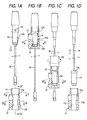
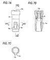
- a first embodiment of the invention will be described with reference to Figs. 1A to 7 for a case where an antenna is fixed to a casing body of a cellular phone, such that the antenna is withdrawably accommodated within the casing body.
- a casing body 10 of the cellular phone serving as a first member is provided with a through hole 12.
- a chamfered part 12a is formed on an outside edge of this hole 12, and a recess 12b is formed on an inner peripheral face of the hole 12 at the same circumferential position as this chamfered part 12a.
- an antenna 14 serving as a second member is formed of resin or the-shaped, and a tongue piece 14a is formed on the antenna 14 in a cantilevered manner.
- a free end of this tongue piece 14a is projected outwardly from an outer peripheral face of the antenna 14, and adapted to be elastically deformed inwardly in a radial direction of the antenna 14.
- An outer face of the tongue piece 14a is in a form of a smooth slope from the base end to the free end, and a chamfered slope face 14b is formed on the tongue piece 14a at one side in a circumferential direction.
- the antenna 14 is provided, on its upper face, with a groove 14c configured such that the antenna 14 can be rotated only in one direction around the axis.
- the antenna 14 is in a substantially cylindrical shape, and contains a power supply spring 16 arranged on its inner peripheral face.
- the power supply spring 16 is appropriately brought into elastic contact with a rod-shaped antenna element 18 which is withdrawably inserted into the antenna 14, thereby to be electrically connected thereto.
- the antenna 14 is inserted into the hole 12, while the tongue piece 14a of the antenna 14 is aligned with the chamfered part 12a of the hole 12 relative to the circumferential direction.
- the chamfered part 12a has such a width as allowing the tongue piece 14a to pass through.
- the tongue piece 14a is elastically deformed inward by a guide of the chamfered part 12a, so that smooth insertion of the antenna 14 is permitted.
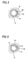
- the tongue piece 14a is elastically restored to be brought into an engaged state as shown in Figs. 1 B and 5, and withdrawal of the antenna 14 is restricted. Because the recess 12b and the chamfered part 12a are formed at the same circumferential positions, the tongue piece 14a can be reliably engaged with the recess 12b.
- the circumferential position of the tongue piece 14a of the antenna 14 can be aligned with the position of the recess 12b because of presence of the chamfered part 12a of the hole 12, it is possible to engage the tongue piece 14a with the recess 12b reliably and easily along with the insertion.
- the tongue piece 14a can be disengaged by rotating the antenna 14 with the aid of the slope face 14b formed on the tongue piece 14a, the antenna 14 can be easily detached from the casing body 10. In this manner, an exchange or the like of the antenna 14 can be easily conducted.
- a boss member 20 serving as a first member which is provided on the casing body of the equipment is formed with a hole 22.
- a cutout 22a is formed on an inner peripheral face of the hole 22, and a slanted face 22b is provided on a side edge of the cutout 22a in a circumferential direction of the hole 22.
- two vertical grooves 22c, 22d are formed so as to extend in an axial direction from an outside edge of the hole 22, and these two vertical grooves 22c, 22d are communicated with each other by a circumferential groove 22e.
- a pin member 24 serving as a second member is provided with a tongue piece 24a formed thereon in a cantilevered manner.
- a free end of this tongue piece 24a is projected outwardly from an outer peripheral face of the pin member 24, and adapted to be elastically deformed inwardly in the radial direction of the pin member 24.
- An outer face of the tongue piece 24a is in a form of a smooth slope from the base end to the free end, and a slanted face 24b is formed on the tongue piece 24a at one side in a circumferential direction which is adapted to be contacted with the slanted face 22b in the cutout 22a of the hole 22.
- a swelled part 24c is formed at an upper end of the pin member 24.
- the pin member 24 is provided with a projection 24d on its outer peripheral face near a lower end thereof. As shown in Figs. 8B and 11, the projection 24d is formed so as to be opposed to one of the vertical grooves 22c when the tongue piece 24a is aligned with the cutout 22a relative to the circumferential direction of the hole 22. Moreover, when the pin member 24 is rotated in such a manner that the slanted face 24b of the tongue piece 24a may be brought into contact with the slanted face 22b of the cutout 22a as shown in Fig. 8C, the projection 24d is so configured to pass through the circumferential groove 22e.
- a circuit board 26 to be fixed to the boss member 20 is provided with a hole 26a having a shape corresponding to an opening of the hole 22 formed with the two vertical grooves 22c, 22d.
- the circuit board 26 is placed on the boss member 20, and the pin member 24 is inserted into the hole 22, having the hole 26a of the circuit board 26 aligned with the hole 22.
- the projection 24d of the pin member 24 is brought into a position aligned with the one vertical groove 22c in the circumferential direction of the hole 22.
- the projection 24d passes through the one vertical groove 22c, and the tongue piece 24a is elastically deformed to permit the insertion.
- the tongue piece 24a is inserted up to the position opposed to the cutout 22a, the tongue piece 24a is elastically restored to be engaged with the recess 22a.
- the projection 24d arrives at a bottom end of the vertical groove 22c, and the insertion is restricted. In this manner, the circuit board 26 can be easily fixed to the boss member 20.
- the slanted face 24b of the tongue piece 24a comes in contacted with the slanted face 22b of the cutout 22a, so that the tongue piece 24a is elastically deformed inwardly to be disengaged from the cutout 22a.
- the projection 24d passes through the circumferential groove 22e, and arrives at a terminal end of the circumferential groove 22e in the disengaged state, thereby to restrict the rotation.
- the projection 24d is allowed to pass through the other vertical groove 22d, and the pin member 24 can be withdrawn from the hole 22. In this manner, the circuit board 26 can be easily detached from the boss member 20.
- a casing body 30 serving as a first member is provided with a through hole 32, and a cutout 32a is formed at an inside end part of the hole 32. Moreover, a slanted face 32b is formed on a side edge of the cutout 32a in a circumferential direction of the hole 32. Additionally, a chamfered part 32c is formed on an outside edge of the hole 32 at the same circumferential position as the cutout 32a. Further, two vertical grooves 32d, 32e are formed on an inner peripheral wall of the hole 32 so as to extend from the outside edge in the axial direction of the hole 32. Inner ends of these vertical grooves 32d, 32e are communicated with each other by a circumferential groove 32f.
- a fixing member 34 serving as a second member is arranged at a base end of an antenna element 36.
- a tongue piece 34a is formed on the fixing member 34 in a cantilevered manner.
- the free end of the tongue piece 34a has an engaging part 34b which is projected outwardly from an outer peripheral face of the fixing member 34.
- the tongue piece 34a can be elastically deformed inwardly in a radial direction of the antenna element 36, until at least a distal end of the engaging part 34b comes into alignment with the outer peripheral face.
- a projection 34c is formed on the outer peripheral face of the fixing member 34 near a lower end thereof.
- the width of the chamfered part 32c is set to be such a width that the tongue piece 34a of the fixing member 34 can pass it through.
- the projection 34c of the fixing member 34 is so adapted as to be opposed to one of the vertical grooves 32d which is formed on the inner peripheral face of the hole 32 from the outside edge, when the tongue piece 34a is aligned with the cutout 32a relative to the circumferential direction of the hole 32. Further, the projection 34c is so formed as to pass through the circumferential groove 34f, when the fixing member 34 is circumferentially rotated in such a direction that the tongue piece 34a may be brought into contact with the slanted face 32b of the cutout 32a. Thereafter, when the fixing member 34 is rotated up to a position where the tongue piece 34a is disengaged from the cutout 32a, the projection 34c which has passed through the circumferential groove 32f is adapted to arrive at the other vertical groove 32e.
- the fixing member 34 can be easily and reliably fixed. It is also possible to easily detach the fixing member 34, by circumferentially rotating the fixing member 34 from the fixed state, and withdrawing the fixing member 34 from the hole 32, after the rotation is restricted.
- all of the holes 12, 22, 32, the members 14, 24, 34 have a substantially circular cross section in a direction perpendicular to the axial direction thereof.
- they are not limited to have such a cross sectional shape, as long as the members 14, 24, 34 can be circumferentially rotated inside the holes 12, 22, 32 in order to disengage the tongue pieces 14a, 24a, 34a from the recess or cutout 12a, 22a, 32a.
- they may be in any cross sectional shape, as long as the members 14, 24, 34 can be inserted into the holes 12, 22, 32, in case where a structure for disengaging the tongue pieces 14a, 24a, 34a by the circumferential rotation is not required.
Landscapes
- Engineering & Computer Science (AREA)
- Computer Networks & Wireless Communication (AREA)
- Snaps, Bayonet Connections, Set Pins, And Snap Rings (AREA)
- Support Of Aerials (AREA)
- Mutual Connection Of Rods And Tubes (AREA)
Applications Claiming Priority (2)
| Application Number | Priority Date | Filing Date | Title |
|---|---|---|---|
| JP2003417929A JP2005180472A (ja) | 2003-12-16 | 2003-12-16 | 固定構造 |
| JP2003417929 | 2003-12-16 |
Publications (1)
| Publication Number | Publication Date |
|---|---|
| EP1544942A1 true EP1544942A1 (de) | 2005-06-22 |
Family
ID=34510615
Family Applications (1)
| Application Number | Title | Priority Date | Filing Date |
|---|---|---|---|
| EP04029609A Withdrawn EP1544942A1 (de) | 2003-12-16 | 2004-12-14 | Befestigungsanordnung |
Country Status (5)
| Country | Link |
|---|---|
| US (1) | US7250912B2 (de) |
| EP (1) | EP1544942A1 (de) |
| JP (1) | JP2005180472A (de) |
| KR (1) | KR20050061370A (de) |
| CN (1) | CN1630132A (de) |
Families Citing this family (4)
| Publication number | Priority date | Publication date | Assignee | Title |
|---|---|---|---|---|
| JP5150330B2 (ja) * | 2008-03-27 | 2013-02-20 | 京セラ株式会社 | ホイップアンテナの取付け構造及び該構造を用いた携帯端末機器、ホイップアンテナの取付け方法 |
| JP4903749B2 (ja) * | 2008-05-14 | 2012-03-28 | 株式会社ニフコ | クリップ |
| US9065170B2 (en) * | 2012-10-04 | 2015-06-23 | Harris Corporation | Communication device comprising an external control with an embedded antenna assembly |
| US9160392B2 (en) | 2014-01-23 | 2015-10-13 | Harris Corporation | Rotary knob with integrated antenna |
Citations (5)
| Publication number | Priority date | Publication date | Assignee | Title |
|---|---|---|---|---|
| DE29811273U1 (de) * | 1998-06-24 | 1998-09-10 | Siemens AG, 80333 München | Antenne für ein funkbetriebenes Kommunikationsendgerät |
| US6215446B1 (en) * | 1999-07-23 | 2001-04-10 | Centurion Wireless Technologies, Inc. | Snap-in antenna |
| US20010004248A1 (en) * | 1999-12-16 | 2001-06-21 | Naoyuki Takagi | Antenna device |
| JP2002141719A (ja) * | 2000-10-31 | 2002-05-17 | Tokin Corp | 携帯無線機用アンテナおよびその製造方法 |
| US20020101380A1 (en) * | 2000-03-07 | 2002-08-01 | Felix Pruss | Antenna connector |
Family Cites Families (2)
| Publication number | Priority date | Publication date | Assignee | Title |
|---|---|---|---|---|
| JP2000252727A (ja) | 1999-02-25 | 2000-09-14 | Yokowo Co Ltd | アンテナの取付構造 |
| JP2005167650A (ja) * | 2003-12-03 | 2005-06-23 | Yokowo Co Ltd | アンテナ取付構造 |
-
2003
- 2003-12-16 JP JP2003417929A patent/JP2005180472A/ja active Pending
-
2004
- 2004-12-14 EP EP04029609A patent/EP1544942A1/de not_active Withdrawn
- 2004-12-15 US US11/011,082 patent/US7250912B2/en not_active Expired - Fee Related
- 2004-12-16 KR KR1020040106931A patent/KR20050061370A/ko not_active Withdrawn
- 2004-12-16 CN CNA2004101020297A patent/CN1630132A/zh active Pending
Patent Citations (5)
| Publication number | Priority date | Publication date | Assignee | Title |
|---|---|---|---|---|
| DE29811273U1 (de) * | 1998-06-24 | 1998-09-10 | Siemens AG, 80333 München | Antenne für ein funkbetriebenes Kommunikationsendgerät |
| US6215446B1 (en) * | 1999-07-23 | 2001-04-10 | Centurion Wireless Technologies, Inc. | Snap-in antenna |
| US20010004248A1 (en) * | 1999-12-16 | 2001-06-21 | Naoyuki Takagi | Antenna device |
| US20020101380A1 (en) * | 2000-03-07 | 2002-08-01 | Felix Pruss | Antenna connector |
| JP2002141719A (ja) * | 2000-10-31 | 2002-05-17 | Tokin Corp | 携帯無線機用アンテナおよびその製造方法 |
Non-Patent Citations (1)
| Title |
|---|
| PATENT ABSTRACTS OF JAPAN vol. 2002, no. 09 4 September 2002 (2002-09-04) * |
Also Published As
| Publication number | Publication date |
|---|---|
| KR20050061370A (ko) | 2005-06-22 |
| US20050179613A1 (en) | 2005-08-18 |
| US7250912B2 (en) | 2007-07-31 |
| JP2005180472A (ja) | 2005-07-07 |
| CN1630132A (zh) | 2005-06-22 |
Similar Documents
| Publication | Publication Date | Title |
|---|---|---|
| CN108019409B (zh) | 适应两个方向上的偏移的销与索环紧固件以及相关的方法 | |
| US7082650B2 (en) | Snap fit mechanism | |
| EP1988416B1 (de) | Optischer Verbinder und Verfahren zur Montage eines optischen Verbinders | |
| EP1873871A2 (de) | Elektrischer Verbinder | |
| EP1174296A2 (de) | Gegenlagerböckchen für Fahrzeugsonnenblenden | |
| US6935887B2 (en) | Connector preventive of incomplete fitting | |
| JPH02227974A (ja) | コネクタハウジングの二重ロック構造 | |
| US7175464B2 (en) | Latching device for a connector | |
| US7250912B2 (en) | Fixing structure | |
| US7244130B2 (en) | Card connector having ejection mechanism | |
| EP0902504A2 (de) | Verbinder mit Verriegelungsglied | |
| US6386897B1 (en) | Electrical plug connection with a plug housing, contact housing and bayonet ring for locking the plug housing in the contact housing | |
| EP0723316B1 (de) | Kartensteckverbinder | |
| JPH08322614A (ja) | バンド部材の連結具 | |
| JP3250208B2 (ja) | バルブソケットの取付構造 | |
| JP3077136B2 (ja) | 組み付け部品のロック構造 | |
| GB2303667A (en) | Releasable socket fastener | |
| US20070004283A1 (en) | Card connector | |
| US7046206B2 (en) | Structure for mounting antenna | |
| EP0978742A3 (de) | Optischer Faser Besfestigungsvorrichtung zur Kopplung mit einem optischen Kommunikationsmodul | |
| JP2006067445A (ja) | モジュール用コネクタロック装置及び該ロック装置を用いたカメラ用モジュール装置 | |
| JP3541748B2 (ja) | 端子の中継構造 | |
| US6468115B2 (en) | Terminal retainer-attached connector | |
| US20250102003A1 (en) | Fastener | |
| KR101526572B1 (ko) | 카메라모듈 체결 소켓 및 홀더 |
Legal Events
| Date | Code | Title | Description |
|---|---|---|---|
| PUAI | Public reference made under article 153(3) epc to a published international application that has entered the european phase |
Free format text: ORIGINAL CODE: 0009012 |
|
| AK | Designated contracting states |
Kind code of ref document: A1 Designated state(s): AT BE BG CH CY CZ DE DK EE ES FI FR GB GR HU IE IS IT LI LT LU MC NL PL PT RO SE SI SK TR |
|
| AX | Request for extension of the european patent |
Extension state: AL BA HR LV MK YU |
|
| AKX | Designation fees paid | ||
| STAA | Information on the status of an ep patent application or granted ep patent |
Free format text: STATUS: THE APPLICATION IS DEEMED TO BE WITHDRAWN |
|
| 18D | Application deemed to be withdrawn |
Effective date: 20051223 |
|
| REG | Reference to a national code |
Ref country code: DE Ref legal event code: 8566 |