EP1544806A2 - Ausrüstung zum automatischen Einzahlen von Banknoten - Google Patents
Ausrüstung zum automatischen Einzahlen von Banknoten Download PDFInfo
- Publication number
- EP1544806A2 EP1544806A2 EP04029436A EP04029436A EP1544806A2 EP 1544806 A2 EP1544806 A2 EP 1544806A2 EP 04029436 A EP04029436 A EP 04029436A EP 04029436 A EP04029436 A EP 04029436A EP 1544806 A2 EP1544806 A2 EP 1544806A2
- Authority
- EP
- European Patent Office
- Prior art keywords
- stack
- banknotes
- belts
- box
- recognized
- Prior art date
- Legal status (The legal status is an assumption and is not a legal conclusion. Google has not performed a legal analysis and makes no representation as to the accuracy of the status listed.)
- Granted
Links
Images


Classifications
-
- G—PHYSICS
- G07—CHECKING-DEVICES
- G07D—HANDLING OF COINS OR VALUABLE PAPERS, e.g. TESTING, SORTING BY DENOMINATIONS, COUNTING, DISPENSING, CHANGING OR DEPOSITING
- G07D11/00—Devices accepting coins; Devices accepting, dispensing, sorting or counting valuable papers
- G07D11/10—Mechanical details
- G07D11/14—Inlet or outlet ports
-
- G—PHYSICS
- G07—CHECKING-DEVICES
- G07D—HANDLING OF COINS OR VALUABLE PAPERS, e.g. TESTING, SORTING BY DENOMINATIONS, COUNTING, DISPENSING, CHANGING OR DEPOSITING
- G07D11/00—Devices accepting coins; Devices accepting, dispensing, sorting or counting valuable papers
- G07D11/40—Device architecture, e.g. modular construction
Definitions
- the present invention relates to an equipment for the automatic deposit of banknotes.
- the invention relates to an equipment for the automatic deposit of stacked banknotes comprising a transaction port for receiving a stack of banknote according to the introductory portions of the principal claims.
- a typical need of the banking automation relates to the possibility to find an equipment for advantageously replacing the functions of the tellers to allow the banking institute, as management entity, to employ this personnel for more profitable activities and enabling the customers to deposit banknotes, without assistance, 24 hours a day.
- a system for the automatic processing of banknotes comprising a device for the deposit and a device for the withdrawal described in PCT Patent Application WO 99/48064 in the name of CTS Cashpro S.r.1.
- the device for the deposit of the banknotes is located in a protected environment with access allowed to selected customers through authorizing codes, whilst the device for the withdrawal can be used by generalized customers and works in an environment open to the public.
- the withdrawal device of the Patent Application WO 99/48064 re-uses a good portion of the banknotes deposited in the deposition device.
- the system results very advantageous.
- the banking institutes can accomplish a continuous recharge of the banknotes to be dispensed, and the customers may obtain an immediate accredit of the deposited amounts.
- this system results rather expensive and its use is limited to special cases.
- a main object of the present invention is to provide an equipment for the automatic deposit of banknotes of relatively limited cost and which can be used with full satisfaction by the management entities and, in a reliable way, by generalized customers and in premises normally open to the public.
- Another object of the invention is to provide an equipment for the automatic deposit of stacked banknotes allowing the handling of relatively high thickness and the return of the stack, in the case of a contrary decision of the customer.
- the equipment for the automatic deposit of banknotes comprises a transaction port for receiving a stack of banknote, a separating device for separating the constituting sheets of the stack and a validation device for discriminating the constituting sheets as recognized banknotes and constituting sheets not recognized according to the characterizing portion of the claim 1.
- the equipment for the automatic deposit of banknotes can comprise a window of access toward the inside, a shutter door for the said window and a thickness control device for the control of the stack according to the characterizing part of claim 12.
- Another object of the invention is to accomplish an equipment of deposit which can easily be added, with limited costs, to machines for the withdrawal of banknotes in broadly tested and possibly already installed systems, without requiring substantial adjunctive spaces and with limited interventions and maintenance costs.
- the equipment for the automatic deposit of banknotes comprises a containing structure of substantially parallelepiped shape according to the characterizing part of claim 15.
- a further object of the invention is to provide an equipment for the automatic processing of banknotes which can receive stacks of relatively high thickness and with undiversified denominations, to separate the banknotes and to reform the stacks, for a possible return, after a check at high velocity.
- the equipment for the automatic processing of banknotes comprises a banknote box provided for shifting in a space adjacent to the transaction port between a first position adjacent to the transaction port and a second position on the path for the recognized banknotes according to the characterizing part of claim 16.
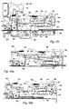
- Represented with 22 with reference to figure 1, is an equipment for the automatic deposit of banknotes.
- the banknotes to be deposited, designated with 23, are piled as sheets of a stack 24 and, after checks, are provided for transfer to a store-safe 26, whereas the respective amounts are accounted and accredited.
- the deposit equipment 22 can operate in association with a machine 27 (Fig. 2) for the withdrawal of banknotes, including a badge reader 28, a screen 29 and a keyboard 31 and connected to a banking system for on-line transactions.
- a machine 27 for the withdrawal of banknotes, including a badge reader 28, a screen 29 and a keyboard 31 and connected to a banking system for on-line transactions.
- the reader, the screen and the keyboard of the machine 27 also constitute for the customers the elements of interface with the deposit equipment 22.
- the equipment 22 comprises a containing structure 32 with a transaction port 33 to receive the stack 24, and includes a thickness control device 34, a separating device 36, a validation device 37 and a transport mechanism with two sections 38 and 39.
- An electronic processing unit 40 feeds and controls the electromechanic components and provides the input-output connections with the system for on-line transactions, specifically with the exemplary machine 27.
- the thickness control device 34 is provided to check a condition of maximum acceptable thickness of the stack 24 whilst the separating device 36 is provided to separate individually the sheets constituting the stack 24.
- the validation device 37 is provided to analyze the nature of the constituting sheets separated by the device 36, recognizing the banknotes acceptable for the deposit and the constituting sheets non-acceptable. The device 37 also recognizes the denominations of the validated banknotes and discriminates, between the non-acceptable constituting sheets, the discards to be manually re-handled and the false banknotes.
- the first section 38 is interposed between the separating device 36 and the validation device 37; the second section 39 is downstream of the device 37 and comprises a plurality of branches to guide and drag the analyzed constituting sheets according to differentiated paths.
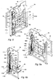
- the containing structure 32 has a substantially parallelepiped shape, with a front 41 and a base 42.
- the front 41 provides a removable panel 43, on which the transaction port 33 is lodged, whilst the base 42 has an output opening 44 of access to the store-safe 26 (Fig. 1).
- a shutter door 46 for the transaction port 33 and a servomechanism for the door 46 which are used together with other components in the thickness control device 34.
- the shutter door 46 constitutes a sensing element for the control device 34.
- the containing structure 32 is relatively narrow, vertically extended in use, and can be mounted above the store-safe 26. Further, the widths of the transaction port 33 and the output opening 44 are a few larger of the height, of smaller dimension, of the acceptable banknotes of higher amount, according to an S.E.F. (Short Edge First) insertion of the stacks 24 in the longitudinal sense of the banknotes.
- S.E.F. Short Edge First
- the equipment 22 includes, as a support for the inside components, a frame 47 having a back plate 48 and a side plate 49.
- the processing unit 40 is mounted on the back plate 48 and is protected by a removable panel.
- the devices 36 and 37 and the sections 38 and 39 of the transport mechanism are mounted on the side plate 49 and project inside the structure 32 to drag the stack 24 or the single banknotes in the longitudinal sense of the banknotes consistent with the direction of insertion.
- the equipment 22 can be easily installed side by side and without substantial increase of space in the area in which the machine 27 for the withdrawal of banknotes (Fig. 2) is already present.
- the containing structure 32 can be lodged in a seat 56, adjacent to the reader 28, the screen 29 and the keyboard 31.
- the structure 32 is removable toward the anterior by means of a handle 57, for accessing the inside components in case of jamming for operations of maintenance in general.
- the containing structure 32 defines a passage space 51 adjacent to the front 41, whilst the separating device 36 and the section 39 of the transport mechanism take up a central section adjacent to the space 51.
- a box assembly 52 is arranged in the passage space 51 with possibility of shifting in vertical.
- the assembly 52 includes a banknote storage box 53 and a discard storage box 54 to temporarily store the banknotes to be deposited and the other sheets of the stack 24 during the procedure of deposit.
- the box 53 is provided to store the stack 24 and the validated banknotes and, respectively, the box 54 can receive the constituting sheets of the separated stack as banknote sub-stack 50 and, respectively, as discard sub-stack 55.
- the separating device 36 defines an input section adjacent to the passage space 51 at the same level of the transaction port 33 and comprises a stack moving mechanism 58 and a separating mechanism 59.
- the mechanism 58 is provided for shifting the stack 24 or the sub-stacks 50, 55 whilst the mechanism 59 is provided for separating the sheets constituting the stacks 24 and the sheets constituting the sub-stacks 50 and 55.
- the banknote box 53 and the discard box 54 are arranged at different heights, high and low, respectively.
- the assembly 52 includes a moving mechanism 60 and the storage boxes 53 and 54 include two respective holding mechanisms 61 and 62 to drag the stack 24 in a step of insertion of the procedure of deposit, and to drag the sub-stacks 50 and 55 in association with the temporary store of the sheets constituting the stack 24.
- the box assembly 52 is mounted on a carriage 63 (Figs. 4 and 13) adjacent to the side plate 49 of the frame 47 and it is operatively connected to a vertical shifting mechanism 64.
- the mechanism 64 is provided for moving the assembly 52, as an elevator, among three positions or levels, namely a reference position "I", a lowest position "II” and a highest position "III".
- the reference position "I" (Figs. 2 and 8) of the assembly 52 is functional to the insertion of the stack 24 in the transaction port 33 and to a possible return of the stack to the customer.
- the lowest position “II” (Fig. 11) relates to particular steps of the procedure of deposit and the highest position "III" (Fig. 12) is functional to the return of the discards to the customer.
- the validation device 37 supplies recognition codes associated with the validated banknotes, the constituting sheets to be re-handled, and the banknotes recognized as false.
- the constitution of the device 37 relates to problems, different from those of the present invention and it is not described herein.
- the store-safe 26 can comprise an input section 65, two deposit drawers 66a and 66b, a drawer of retract 67, a drawer of false 68 and suitable diverters.
- the input section 65 is arranged directly below the output opening 44 and the diverters are servo-dependent on the codes of the validation device 37 to address for the storing the validated banknotes toward the deposit drawers 66a and 66b and, respectively, the other constituting sheets to the drawer of retract 67 for being manually re-handled or toward the drawer of false 68.
- the section 39 of the transport mechanism is provided for moving the constituting sheets emerging from the device 37 (Fig, 2) along a common path 69 and from the path 69 along a path of deposit-capture 71 or, in alternative, toward a path 72 for the recognized banknotes or toward a path 73 for the constituting sheets not recognized and to be manually re-handled.
- the path of deposit-capture 71 is directed toward the output opening 44 for transferring to and storing in the store-safe 26 the validated and accepted banknotes, the constituting sheets to be re-handled and the false banknotes.
- the path 72 for the recognized banknotes is directed toward the box 53, whereas the path 73 for the constituting sheets not recognized is directed toward the box 54 when the assembly 52 (Fig. 11) is at the lowest position "II.”
- the path 72 for the recognized banknotes and the path 73 for the constituting sheets not recognized have end portions, which define sections of output arranged at different heights underneath the section of input of the separating device 36 (Fig. 2) and in condition of substantial vertical co planarity.
- the sections of output of the paths 72 and 73 result adjacent to the banknote box 53 and, respectively, to the discard box 54.
- the box assembly 52 (Fig. 1), the separating device 36, the validation device 37 and the sections 38 and 39 of the transport mechanism include couples of photo-emitters and photo-sensors represented in schematic way by alphabetical letters, which detect the presence of the banknotes 24 at the input section and along particular portions of the various paths.
- a photoelectric couple “A” is arranged at the input section of the box assembly 52; two couples “B", “C” are provided for the box 53 and two couples “D” and “E” are provided for the box 54.
- the separating device 36 includes a couple “F” at the input section, a couple “G” at an intermediate section, and two couples “H” and “I”, at the input and the output of the separating mechanism 59.
- the section 38 of the transport mechanism includes a photoelectric couple "L” at the input section and a couple "M” at its output.
- the section 39 of the transport mechanism includes a photoelectric couple "N" at the input section and two couples “O” and “P” at two intermediate sections of the common path 69.
- Two photoelectric couples "Q", “R” are arranged at intermediate portions of the paths 72 and 73, whereas two couples "S” and “T” detect the passage of the banknotes through the output sections of the path 73 and, respectively, through the path 71 adjacent to the output opening 44.
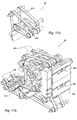
- the separating device 36, the validation device 37 and the box assembly 52 constitute functional unities which may be easily removed from the side plate 49 or from the carriage 63 (Fig. 4) in connection with operations of maintenance or for substitutions.
- the unities are connected with the electronic processing unit 40 through cables and connectors not shown in the figures.
- the components of the equipment 22 are easily accessible through the side of the containing structure 32 in the case of jamming and to free the banknotes from clogged mechanisms and devices.
- the separating device 36, the validation device 37 and the sections 38 and 39 of the transport mechanism are mounted on a plate 74 fixed not too far from the side plate 49 of the frame 47 and the vertical shifting mechanism 64 is mounted on the plate 49.
- the separating device 36 and the validation device 37 are fixed on the plate 74 by means of pivots 76a, 76b, 76c and 76d and, respectively, small-columns 77a, 77b and 77c.
- the carriage 63 (Fig. 13) includes a suitably shaped plate and the box assembly 52 is mounted on this plate by means of shims 78a, 78b, 78c and 78d.
- Figure 3 shows a flow chart 81 including the principal steps which are followed by the equipment 22 for the execution of an operation of deposit of banknotes, according to an exemplary application program.
- the operation of deposit starts with the insertion of a magnetic badge in the reader 28.
- the customer can start the procedure of deposit through the keyboard 31 and on instructions displayed on the screen 29.
- an insertion step 82 the customer inserts the stack 24 of banknotes to be deposited in the transaction port 33 with partial projection and lodging of the stack in the storage box 53.
- the detection of banknotes by the photoelectric couple "A" in the box 53 causes the actuation of the control device 34.
- the shutter door 46 will go down in contact with the upper surface of the stack 24 for the control of the thickness and a following re-opening.
- a checking step 83 If, in a checking step 83, the controlled thickness of the stack 24 is over the permissible limit, the process of deposit will be interrupted in a step of return 84 for allowing the customer to remove the stack 24 from the port 33.
- the holding mechanism 61, the moving mechanism 60 of the assembly 52 and the servomechanism for the door 46 are actuated in sequence.
- the stack 24 will be completely transferred to the storage box 53 and the door 46 will go completely down and locked.
- the stack 24 is transferred to the separating device 36, and the vertical shifting mechanism 64 is activated for positioning the box assembly 52 at the position "II".
- the banknote box 53 is now arranged in front of the section of output of the path 72 for the recognized banknotes, whilst the discard box 54 is in front of the section of output of the path 73 for the constituting sheets not recognized.
- a checking and validation step 86 the components of the stack 24 are separated and the single sheets pass one after the other in front of the validation device 37. Then, the section 39 of the transport mechanism drags the constituting sheets along the common path 69 and along the paths 71 or 72 or 73 in response to the recognition codes of the sheets.
- the false banknotes are directly addressed along the path 71 and, through the output opening 44, captured in the drawer of false 68 of the store-safe 26.
- the validated banknotes of the path 72 are piled in the storage box 53 to form a banknote sub-stack 50.
- the constituting sheets not recognized, as generic sheets or, typically, worn-out banknotes are addressed along the path 71 and are piled in the storage box 54 to form a discard sub-stack 55.
- a checking step 87 examines the presence of non-recognized constituting sheets in the discard box 54. In positive, the processing unit 40 determines a return step 88 in which the box assembly 52 is positioned at the highest position "III", the shutter door 46 opens and the discard sub-stack 55 is moved into the transaction port 33 to allow the customer the withdrawal of the sub-stack 55.
- the discard sub-stack 55 is moved into the devices 36, and 37, in a step of capture 91, and the transport mechanism finally deposits the constituting sheets in the drawer of retract 67.
- the electronic unit 40 proceeds to process the validated banknotes.
- a decision box 92 there is verified if the storage box 53 contains validated banknotes and, if there are no banknotes, the transaction is completed.
- checking step 93 the customer is allowed to interrupt the procedure of deposit.
- the mechanism 64 positions again the box assembly 52 at the position "I" in a step 94, whereas the moving mechanism 60 drags the banknote sub-stack 50 into the device 36 for another separating operation.
- a final step 96 the banknotes are validated and the respective values are accounted and accredited.
- the transport mechanism drags the banknotes along the path 71 and, through the output opening 44, to the store-safe 26 for the storage in the drawer 66a or 66b, whereby completing the transaction.
- a return step 97 is activated in which the assembly 52 is positioned at the reference position "I".
- the sub-stack 50 is moved into the transaction port 33 and the door 46 is opened for the withdrawal of the validated banknotes.
- a decision box 98 there is checked the withdrawal of the banknotes: in the positive, the transaction is completed. If, on the contrary, the customer does not takes up the banknotes, after a pre-defined period of delay, the sub-stack 50 is moved into the devices 36 and 37, in a step of capture 99, and the transport mechanism stores the banknotes in the drawer of retract 67.
- the equipment 22 allows the execution of operation of deposit different from the ones above described.
- the various devices and the component mechanisms can follow different sequences and programming, according to rules or specific needs of the management entity. This is particularly true for what it concerns the procedures of return and the processing of the discards.
- the thickness control device 34 (Figs. 4, 5, 6a and 6b) and the door actuating servomechanism include, as common components, a micro-motor 101, a transmission assembly between the micro-motor 101 and the door 46 and a sensing group, including the door 46, used as sensing element for recognizing a pre-defined thickness of the stack 24 with respect to a reference plane 102.
- the reference plane 102 constitutes a surface of support for the stack 24 to be deposited.
- the panel 43 defines a window 103 of passage for the banknotes, which is delimited in the lower part by the reference plane 102.
- the shutter door 46 is connected slidably and in contact with the panel 43, for closing and opening the window 103. In the closed position, the door 46 is in contact with the reference plane 102, can be locked in this position and, preliminarily to the opening, can be released by the servomechanism.
- the shutter door 46 is obtained from a shaped steel plate 104.
- This plate includes a side with two vertical slots 1061 and 106h and a refolded lower edge.
- the slots 1061 and 106h are lined up and arranged at different heights, whilst the lower edge is provided for contacting the reference plane 102.
- a guide side of the plate 104, opposite to the slotted side, is slidably contrasted by an iron member 107, and the slots 1061 and 106h are slidably engaged by pivots 1081 and 108h provided of contrast head.
- the iron member 107 and the pivots 1081 and 108h are firmly fixed rear to the panel 43, and the whole is sized to withstand possible burgling actions on the shutter door 46.
- the micro-motor 101 is mounted above the window 103 through a bracket 109; the transmission assembly comprises a disk 111 keyed on the output shaft of the micro-motor 101 with function of crank, a control pin 112 and a bar 113.
- the bar 113 is fulcrum-mounted on a lug of the plate 104 adjacent to the upper slot 106h. This bar has the function of a connecting rod and includes a slot 114 in which the pivot 112 is slidably engaged.
- the above described cinematic mechanism is of lost motion type, and a spring 116 operative on a lug of the plate 104 normally pushes downward the door 46.
- the control pin 112 In condition of closed door (Fig. 6b), the control pin 112 is low adjacent to the upper portion of the slot 114 and, in absence of any lock, the door 46 may be easily lifted against the action of the spring 116 through the stroke allowed by the slot 114.
- the control pin 112 In condition of open door (Figs. 5 and 6a), the control pin 112 is high, engaged with the upper portion of the slot 114.
- the sensing group of the control device 34 includes three photoelectric couples 117a, 117b and 117c and two sensing lugs 118a and 118b.
- the lugs 118a and 118b are parts of the plate 104 close to the slots 106.
- the photoelectric couples cooperate with the lugs to supply information regarding the lowest position of the door 46, of contrast with plane 102, the highest position, of opening, and the intermediate position, of reference.
- the photoelectric couples 117a and 117b are adapted to cooperate with the lug 118a in association with the closing and the opening of the door, whereas the photoelectric couple 117c can cooperate with the lug 118b in relation to the thickness control of the stack.
- An arrest tooth 119 (Figs. 5, 6a and 6b) and a hook 121 are provided for the function of locking of the door 46.
- the tooth 119 is fixed on the plate 104, close to the higher slot 106h.
- the hook 121 it is fulcrum-mounted as a bridge on a pivot of the bracket 109 and is provided of an upper inclined edge.
- the hook 121 defines a condition of lock and a condition of release of the door 26 and is urged toward the condition of lock by a spring 122.
- the hook 121 engages the tooth 119 whilst, in the condition of release, the tooth is disengaged.
- a releasing pin 123 actuatable by the micro-motor 101 and a lug 124 of the hook 121 are provided.
- the releasing pin 123 is keyed on the disk 111 on opposed sides beside the pivot 112, whilst the lug 124 is adapted to cooperate with the pivot 112 to set the hook 121 in the condition of release, in a pre-defmed position of the disk 111.
- the micro-motor 101 (Fig. 6b) initially causes the shifting of the hook 121 in the condition of release through the action of the releasing pin 123 on the lug 124.
- the arrest tooth 119 is released and the door can lift for the action of the spring 116, following the movement of the pivot 112 with the lower portion of the slot 114.
- the complete opening of the door is recognized by the obscuring of the sensor in the couple 117b by the lug 118a, with a consequent arrest of the micro-motor 101.
- the tooth 119 is above the hook 121 and does not cause any obstacle to lowering movements less than the one of contact with the plane 102.
- the arrest tooth 119 moves the hook 121 toward the condition of release by means of the inclined edge and against the action of the spring 122.
- the movement proceeds until the door 46 goes in contact with the plane 102 carrying the tooth 119 underneath the hook 121, and allowing the spring 122 to sharply move the hook 121 to the condition of lock.
- the complete closing of the door 46 is recognized by the obscuring of the sensor of the couple 117a by the lug 118a.
- the spring shifting of the door 46 prevents possible injuries, in the case a customer left the fingers in the transaction port 33 during the closing of the door. In these conditions the hook 121 does not interfere with the door 46, whereas the control through the spring 116 allows the lifting of the door and the easy releasing of the fingers against the light action of the spring.
- the reference position of the door 46 is relative to a predetermined height of its lower edge from the reference plane 102. This height corresponds to a thickness "S max" of the stack 24 to be deposited, less then the height of the window 103, for surely enabling the handling of the stack and its possible return in a reliable way.
- the thickness "S max" allows the deposit of one hundred banknotes, also under conditions of relative worn-out thereof.
- the checking step 83 provides a cycle of closing and reopening of the door 46 after the opening of the transaction port 33 and the insertion of the stack 24.
- the sensor of the photoelectric couple 117c is not darkened by the lug 118b and the electronic unit 40 interrupts the procedure of deposit at the end of the check, and displays in the screen an error of insertion for the excess of banknotes.
- the lug 118b obscures the sensor of the photoelectric couple 117c during the descent of the door 46.
- the deposit proceeds in rapids sequence, as previously described, with holding of the stack 24 by the mechanism 61 (Fig. 8), its dragging and the actuation of the micro-motor 101 for the closing and the locking of the door 46.
- the box assembly 52 (Figs. 7, 8, 9 and 10) comprises a frame 127 of substantially parallelepiped shape, vertically extended, having two sides 128 and 129.
- the respective moving mechanism 60 includes a motor 131 and three couples of endless conveyer belts 132, 133 and 134.
- the belts 132, 133 and 134 are horizontally extended and the upper and lower branches have a useful length larger than the length of the longest acceptable banknotes.
- the upper and lower branches of each couple of belts are substantially coplanar and are at such a distance suitable for cooperating with central areas of all the typologies of the banknotes of the stack 24, according to a known technique.
- the couples of conveyer belts 132 and 134 are arranged on an upper surface in the banknote box 53 and, respectively, on a lower surface in the discard box 54: the lower branches of the couple of belts 132 are arranged above the upper branches of the couple 133 and the upper branches of the couple 134 are below the lower branches of the couple of belts 133.
- the holding mechanisms 61 and 62 are provided to move up and down the couples of belts 132 and 134 relatively to the belts 133, by varying the distance of the lower branches of the belts 132 with respect to the upper branches of the belts 133 and the distance of the upper branches of the belts 134 with respect to the lower branches of the belts 133.
- the holding mechanism 61 defines three different configurations.
- the first configuration of medium distance between the belts 132 and 133 is associated to the reception of the stack 24 through the transaction port 33, jointly to the position "II" of the assembly 52.
- the space between the belts left to the stack is a little larger of "S max", for an optimal insertion of the stack. Further, there is prevented that the banknotes 23 on top of the stack can slip and get jammed in the cinematic mechanisms of the banknote box 53.
- the second configuration of minimum distance between the belts 132 and 133, is associated to the holding of the stack 24 or the sub-stack 50 for the integral shifting of the respective constituting sheets by means of the upper and lower belts.
- the third configuration, of maximum distance between the belts 132 and 133 is associated to the reception of the validated banknotes jointly with in the position "II" of the assembly 52.
- the space for the reception of the banknotes is at a maximum for an optimal formation of the banknote sub-stack 50.
- the couple of endless belts 133 is common to the storage boxes 53 and 54 and is in engagement with respective rollers.
- the rollers are supported in the rotation in a central area of the frame 127 and include a motor roller 138.
- the couples of endless belts 132 and 134 are in engagement with respective guide rollers including motor rollers 139 and 140.
- the rollers in engagement with the belts 132 and 134 are supported in the rotation, through intermediate elements, by platforms 141 and 142 provided of transversal axes 143 and 144 and shiftable by the holding mechanisms 61 and 62.
- the platforms 141 and 142 have possibility of vertical movement between the sides 128 and 129 of the frame 127.
- the axes 143 and 144 are keyed, at an end, on respective slide members 146 and the motor rollers 139 and 140 carry respective guide rollers 147.
- the slide member 146 are slidable on a guide iron member 148 mounted vertically on the side 128, whilst the two rollers 147 are slidable on two vertical slots 149 of the side 129, lined up one another.
- the holding mechanisms 61 and 62 include each one a cam mechanism connected with the motor 136, 137, an elastic joint member interconnected between the cam mechanism and the shafts 143, 144 and sensor elements to define different configurations of the cam mechanism.
- the cam mechanism For the holding mechanism 61, the cam mechanism provides three configurations associated with the above described configurations of the belts 132 and 133.
- a first configuration is associated to a maximum distance between the belts for the reception of the constituting sheets not recognized and the formation of the discard sub-stack 55 in the position "II" of the assembly 52.
- a second configuration, of holding for the sub-stack, is associated to the shifting of the sub-stack is 55 by means of the upper belts toward the transaction port 33.
- the cam mechanisms of the mechanisms 61 and 62 include respective disks 151 and 152 with a control pin 153, cam follower levers 154 and 155, each one with a slot 156 and an arm 157, and fork levers 158 and 159.
- the disks 151 and 152 are connected in the rotation with the motor 136, 137 and have function of crank, whereas the fork levers 158 and 159 are connected with the shafts 143 and 144 of the platforms 141 and 142.
- the slots 156 of the levers 154 and 155 are in engagement with the control pins 153 of the disks 151 and 152 and the arms 157 are connected with the fork levers 158 and 159 through elastic joints having respective springs 160.
- the sensor elements include three photoelectric couples 161a, 161b and 161c which detect three angular positions of the disk 151, and two photoelectric couples 162a and 162b which detect two angular positions of the disk 152.
- the positions detected by the photoelectric couples 161a, 161b and 161c respectively correspond to the distances, medium, maximum and of holding of the belts 132 with respect to the belts 133.
- the positions detected by the couples 162a and 162b correspond to the maximum distance and the distance of holding of the belts 134 with respect to the belts 133.
- the roller 138 is put in rotation by the motor 131 through a transmission belt 163 and the rollers 139 and 140 are put in synchronous rotation with the roller 138 through two cinematic chains including toothed wheels, toothed belts and two flexible belts 164 and 165.
- the flexible belts allow the transmission of the motion for the different positions of the platforms 141 and 142.
- the senses of rotation of the motor rollers 138, 139 and 140 are such that the direction of motion of the lower branches of the couple 132 is consistent with the one of the upper branches of the couple 133 and the direction of motion of the upper branches of the couple 134 is consistent with the one of the lower branches of the couple 133.
- the couple of belts 132 and 134 are spaced apart from the couple of belts 133.
- the spaces left in the boxes 53 and 54 are sufficient for free movements of a stack 24 or a banknote sub-stack 50 supported on the belts 133 and a discard sub-stack 55 supported on the belts 134.
- the couple of belts 132 or 134 is urged against the couple of belts 133 and holds the stack 24 or the sub-stack sandwiched between the couples of belts for the action of the spring 160.
- the couples of belts 132 and 133 or 133 and 134 operate, in coordinated and synchronous way, on the overlapped constituting sheets, ensuring an integral movement of the stacks 24 or the sub-stacks 50 and 55.
- the shifting mechanism 64 of the box assembly 52 (Figs. 2, 4 and 13) comprises a couple of vertical guides 176 for the carriage 63, a motor 177 and a toothed belt 178.
- the belt 178 extends vertically trough the whole stroke of the carriage 63 and is connected in the rotation with the motor 177 through a toothed transmission belt.
- the carriage 63 is fixed on a branch of the belt 178 and is connected to a couple of springs 179, of compensation for the weight of the box assembly 52.
- the banknote box 53 In the position "I" of the box assembly 52, the banknote box 53 is adjacent to the transaction port 33 and, at the moment of insertion, a stack 24 arranged on the reference plane 102 of the transaction port partially bears on the couple of belts 132.
- the holding mechanism 61 can move down the couple of upper belts 132 for holding the stack between the two couples of belts, whereas the moving mechanism can transfer the whole stack 24 on the separating device 36.
- the storage box 53 is adjacent to the end portion of the path 72 to receive the recognized banknotes.
- the storage box 54 is adjacent to the end portion of the path 73 to receive the constituting sheets not recognized, whilst the holding mechanisms 61 and 62 hold the belts 132 and 134 spaced apart from the couple of belts 133.
- the section 39 of the transport mechanism drags, at high velocity, the banknotes to the storage box 53 and the constituting sheets not recognized to the storage box 54, and form the banknote sub-stack 50 on the belts 133 and the discard sub-stack 55 on the belts 134.
- the electronic unity 40 actuates the holding mechanism 62 of the box 54, lifting the belts 134 so as to stop the discard sub-stack 55 against the belts 133. Then, the unity 40 actuates the mechanism 64, moving upwardly the assembly 52 up to the position "III.”
- the discard box 54 is adjacent to the transaction port 33, with the lower branch of the belts 132 and the upper portion of the discard sub-stack a little below the top edge of the window 103 and the higher branch of the belts 134 a little above the surface 102.
- the banknote box 53 is above the window 103.
- the unity 40 actuates in sequence the door servomechanism for its opening and the moving mechanism 60 of the assembly 52 and the holding mechanism 62 for the withdrawal of the belts 134.
- the discard sub-stack 55 can be moved on the reference plane 102 for the return, whilst the banknote sub-stack 50 of the box 53 is higher than the window 103, arrested against a wall of arrest of the front 41 during the movement of the belts 133.
- the electronic unity 40 actuates in sequence the holding mechanism 62 for the condition of holding of the belts 134 and the moving mechanism 60 to drag the sub-stack in the device 36 and the door servomechanism for its closing, starting the capture in the drawer of retract. Also in this case, the banknote sub-stack 50 of the box 53 is higher than the window 103, arrested against the wall of arrest of the device 36.
- the separating device 36 (Figs. 2 and 14) comprises a horizontal extended frame 181 with two sides 182 and 183.
- the stack moving mechanism 58 includes a motor 184, two endless conveyer belts 186 and 187 and a contrast mechanism 188.
- the conveyer belts 186 and 187 are set at different heights according to an axial surface and have horizontal extension.
- the belts 186 and 187 are in engagement with respective guide rollers and a motor roller and are arranged in an intermediate area of the frame 181 to centrally cooperate with the stack 24 or the sub-stacks 50 or 55 and according to the longitudinal axes.
- the stack moving mechanism 58 defines a movement surface 189 of the stack 24 or the sub-stack 50, 55 substantially coplanar with the surface of the transaction port 33 and comprises an input section adjacent to the box assembly 52, an intermediate section and an output section.
- the separation mechanism 59 is adjacent to the section of output and is adapted to separate the constituting sheets of a stack 24 or the sub-stack 50, 55 positioned between the sections intermediate and of output of the surface 189.
- the transport belt 186 is mounted in a lower portion of the frame 181 and its upper branch is on the movement surface 189.
- the belt 187 is mounted on a support structure 191 arranged longitudinally above of the surface 189, with the lower branch arranged directly above the upper branch of the belt 186.
- the belt 186 has a useful length greater of the longest acceptable banknotes and extends through a main portion of the frame 181 beginning from the input section.
- the conveyer belt 187 has a smaller length and extends between the input section and the intermediate section of the frame 181.
- the contrast mechanism 188 is adapted to move in height the structure 191, varying the distance of the lower branch of the conveyer belt 187 with respect to the upper branch of the belt 186.
- a stack 24 or a sub-stack 50, 55 are free of movement on the surface 189.
- the stack 24 or the sub-stack 50, 55 are opposed by the conveyer belts 186 and 187 for being moved integrally toward the separation mechanism 59.
- the motor 184 is directly connected in the rotation with the motor roller of the conveyer belt 186.
- the motor roller of the conveyer belt 187 is connected in the rotation with the motor 184 through a cinematic chain comprising an elastic belt for compensating the different heights of the parts, with synchronous and concurrent motion of the belts 186 and 187.
- the support structure 191 is connected with the frame 181 through an articulated parallelogram including an upper lever 192 and a lower lever 193, both of rocker arm type.
- the contrast mechanism 188 includes an actuating motor 194 and a crank 196 connected in the rotation with the motor 194 and adapted to cooperate, through a roller 197, with a lug 198 of the lever 192.
- a spring 199 operative on the lever 192, pushes downward the structure 191 whilst, in the condition of rest, the crank 196 holds the structure 191 in the lifted position.
- the separating mechanism 59 includes in the lower part a series of separating rollers 202, a series of counter-rollers 203, a separating motor 204 and a pressure assembly 206 for the stack 24 or the sub-stack 50, 55.
- the rollers 202 are coaxial each the other and are rotated by the motor 204 in the sense of separation.
- the counter-rollers 203 are also coaxial, interposed with interference between the rollers202 and are rotated by the motor 204 in a sense opposite to the direction of separation to avoid any double feed of the banknotes and according to a well known technique.
- the pressure assembly 206 (Figs. 15, 16a and 16b) includes a sustaining structure 207 with a lower guiding plate and two pinch rollers 208 which longitudinally extends between the sections intermediate and of output of the movement surface 189.
- the guiding plate and the rollers 208 are arranged directly above the higher branch of the belt 186 and the sustaining structure 207 is connected with the frame 181 through an articulated parallelogram.
- This parallelogram comprises an upper lever 209 and a lower lever 211 and is urged downward by a spring 212 connected to the lever 209.
- the assembly 206 is connected with the contrast mechanism 188 through a lug 213 of the lever 211 and an end 214 of the lever 193.
- the connection of the two levers 193 and 211 is such that to the lifted position and to the holding position of the belt 187 correspond a lowered position and, respectively, a lifted position of the structure 207.
- the sections 38 and 39 of the transport mechanism include two couples of endless transport belts 216 and 217 in which the belts are arranged side by side on guide rollers mounted on the plate 74.
- the banknotes 23 are held on the transport belts or followed in the movement by suitable counter-belts, also of endless type, urged against the transport belts and driven by other rollers mounted on the plate 74. Further, the banknotes are guided by guide tiles in the output areas or in the input sections of the various devices.
- the transport belts and the counter-belts are actuated in synchronism by a transport motor 218 mounted on the plate 74 and through belts not shown in the figures.
- the section 38 (Figs. 2 and 15a) of the transport mechanism includes one couple of counter-belts represented with 219.
- the section 39 (Figs. 2 and 15b) includes a couple of counter-belts 221 for the definition of the common path 69 and the path of deposit-capture 71 and two couples of counter-belts 222 and 223 which respectively define the path 72 and the path 73.
- the section 39 of the transport mechanism includes a diverter member 224 and a diverter member 226 actuatable by respective electromagnets 227 and 228, in turn servo-dependent on the validation device 37.
- the diverter 224 moves the banknotes 23 of the common path 69 along the path 72 and the diverter 226 moves the discards of the path 71 along the path 73.
- the movement of the banknotes and the discards in the output area and at the end portions of the paths 71, 72 and, respectively 73, is actuated by couples of groups of opposite rollers 229, 231 and 232 connected in the rotation with the motor 218.
- the couple of rollers 229 is arranged above the output opening 44 whilst the couples of rollers 231 and 232 are protected by a wall 233 and are arranged in front of respective windows 234 and 236, at different heights of the wall 23.
Landscapes
- Physics & Mathematics (AREA)
- General Physics & Mathematics (AREA)
- Pile Receivers (AREA)
- Financial Or Insurance-Related Operations Such As Payment And Settlement (AREA)
- Vending Machines For Individual Products (AREA)
- Pinball Game Machines (AREA)
- Control Of Vending Devices And Auxiliary Devices For Vending Devices (AREA)
Applications Claiming Priority (2)
| Application Number | Priority Date | Filing Date | Title |
|---|---|---|---|
| ITTO20031011 | 2003-12-16 | ||
| IT001011A ITTO20031011A1 (it) | 2003-12-16 | 2003-12-16 | Apparecchiatura per il deposito automatico di banconote. |
Publications (3)
| Publication Number | Publication Date |
|---|---|
| EP1544806A2 true EP1544806A2 (de) | 2005-06-22 |
| EP1544806A3 EP1544806A3 (de) | 2006-04-05 |
| EP1544806B1 EP1544806B1 (de) | 2008-02-13 |
Family
ID=34509521
Family Applications (1)
| Application Number | Title | Priority Date | Filing Date |
|---|---|---|---|
| EP04029436A Expired - Lifetime EP1544806B1 (de) | 2003-12-16 | 2004-12-13 | Ausrüstung zum automatischen Einzahlen von Banknoten |
Country Status (6)
| Country | Link |
|---|---|
| EP (1) | EP1544806B1 (de) |
| AT (1) | ATE386316T1 (de) |
| AU (1) | AU2004240170B2 (de) |
| DE (1) | DE602004011740T2 (de) |
| ES (1) | ES2301924T3 (de) |
| IT (1) | ITTO20031011A1 (de) |
Cited By (8)
| Publication number | Priority date | Publication date | Assignee | Title |
|---|---|---|---|---|
| WO2007057471A1 (en) * | 2005-11-21 | 2007-05-24 | Cts Cashpro S.P.A. | Equipment for processing banknotes in stack |
| WO2007101880A3 (en) * | 2006-03-09 | 2007-12-13 | Cts Cashpro Spa | Automatic machine for the deposit and withdrawal of cash |
| WO2008030819A1 (en) * | 2006-09-05 | 2008-03-13 | Mei, Inc. | Bulk document feeder with removable cartridge |
| WO2009083094A1 (de) * | 2007-12-21 | 2009-07-09 | Giesecke & Devrient Gmbh | Vorrichtung für die annahme und ausgabe von banknoten |
| WO2009083140A1 (de) * | 2007-12-21 | 2009-07-09 | Giesecke & Devrient Gmbh | Vorrichtung für annahme und ausgabe von banknoten |
| DE102009049516A1 (de) * | 2009-10-15 | 2011-04-21 | Giesecke & Devrient Gmbh | Vorrichtung für Einzahlung oder Auszahlung von Banknoten |
| US9357663B2 (en) | 2014-04-02 | 2016-05-31 | Buerkert Werke Gmbh | Electronic unit of a fluid sensor or valve and fluid sensor or fluid valve unit |
| CN108198330A (zh) * | 2018-03-19 | 2018-06-22 | 浙江银信博荣电子科技股份有限公司 | 双向闸门机构 |
Families Citing this family (1)
| Publication number | Priority date | Publication date | Assignee | Title |
|---|---|---|---|---|
| JP5500196B2 (ja) * | 2012-03-27 | 2014-05-21 | 沖電気工業株式会社 | 紙幣処理装置 |
Family Cites Families (5)
| Publication number | Priority date | Publication date | Assignee | Title |
|---|---|---|---|---|
| US4050562A (en) * | 1974-04-22 | 1977-09-27 | Mars, Inc. | Banknote escrow and stacker apparatus and method |
| DE3216830C2 (de) * | 1981-05-09 | 1985-11-07 | Laurel Bank Machines Co., Ltd., Tokio/Tokyo | Banknoten-Ein/Ausgabe-Vorrichtung |
| GB9323709D0 (en) * | 1993-11-15 | 1994-01-05 | Ncr Int Inc | Depository apparatus for envelopes and single sheets |
| US6607081B2 (en) * | 1996-11-15 | 2003-08-19 | Diebold, Incorporated | Automated transaction machine system |
| JPH11278665A (ja) * | 1998-03-30 | 1999-10-12 | Glory Ltd | 紙幣束収納投出装置および紙幣束入出金機 |
-
2003
- 2003-12-16 IT IT001011A patent/ITTO20031011A1/it unknown
-
2004
- 2004-12-13 ES ES04029436T patent/ES2301924T3/es not_active Expired - Lifetime
- 2004-12-13 EP EP04029436A patent/EP1544806B1/de not_active Expired - Lifetime
- 2004-12-13 DE DE602004011740T patent/DE602004011740T2/de not_active Expired - Lifetime
- 2004-12-13 AT AT04029436T patent/ATE386316T1/de not_active IP Right Cessation
- 2004-12-16 AU AU2004240170A patent/AU2004240170B2/en not_active Ceased
Cited By (13)
| Publication number | Priority date | Publication date | Assignee | Title |
|---|---|---|---|---|
| US7997576B2 (en) | 2005-11-21 | 2011-08-16 | Cts Cashpro S.P.A. | Equipment for processing banknotes in stack |
| WO2007057471A1 (en) * | 2005-11-21 | 2007-05-24 | Cts Cashpro S.P.A. | Equipment for processing banknotes in stack |
| WO2007101880A3 (en) * | 2006-03-09 | 2007-12-13 | Cts Cashpro Spa | Automatic machine for the deposit and withdrawal of cash |
| US8025282B2 (en) | 2006-03-09 | 2011-09-27 | Cts Cashpro S.P.A. | Automatic machine for the deposit and withdrawal of cash |
| WO2008030819A1 (en) * | 2006-09-05 | 2008-03-13 | Mei, Inc. | Bulk document feeder with removable cartridge |
| US8662490B2 (en) | 2006-09-05 | 2014-03-04 | Mei, Inc. | Bulk document feeder with removable cartridge |
| EP2254096A1 (de) * | 2006-09-05 | 2010-11-24 | MEI, Inc. | Mengen-dokumentzuführungsvorrichtung mit wechselbarer Kassette |
| WO2009083094A1 (de) * | 2007-12-21 | 2009-07-09 | Giesecke & Devrient Gmbh | Vorrichtung für die annahme und ausgabe von banknoten |
| WO2009083140A1 (de) * | 2007-12-21 | 2009-07-09 | Giesecke & Devrient Gmbh | Vorrichtung für annahme und ausgabe von banknoten |
| DE102009049516A1 (de) * | 2009-10-15 | 2011-04-21 | Giesecke & Devrient Gmbh | Vorrichtung für Einzahlung oder Auszahlung von Banknoten |
| US9357663B2 (en) | 2014-04-02 | 2016-05-31 | Buerkert Werke Gmbh | Electronic unit of a fluid sensor or valve and fluid sensor or fluid valve unit |
| CN108198330A (zh) * | 2018-03-19 | 2018-06-22 | 浙江银信博荣电子科技股份有限公司 | 双向闸门机构 |
| CN108198330B (zh) * | 2018-03-19 | 2024-01-30 | 浙江银信博荣电子科技股份有限公司 | 双向闸门机构 |
Also Published As
| Publication number | Publication date |
|---|---|
| DE602004011740T2 (de) | 2009-02-05 |
| ATE386316T1 (de) | 2008-03-15 |
| EP1544806A3 (de) | 2006-04-05 |
| DE602004011740D1 (de) | 2008-03-27 |
| AU2004240170A1 (en) | 2005-06-30 |
| ITTO20031011A1 (it) | 2005-06-17 |
| ES2301924T3 (es) | 2008-07-01 |
| EP1544806B1 (de) | 2008-02-13 |
| AU2004240170B2 (en) | 2010-08-19 |
Similar Documents
| Publication | Publication Date | Title |
|---|---|---|
| US7784787B2 (en) | Equipment for the automatic deposit of banknotes | |
| US7870997B2 (en) | ATM that can center different sized cash stacks in a cash outlet opening | |
| KR100417268B1 (ko) | 지폐취급장치 | |
| EP1413996B1 (de) | Maschine für die Einzahlung und Ausgabe von Banknoten | |
| US9315355B2 (en) | Paper sheet processing device | |
| EP2546809B1 (de) | Vorrichtung zur Handhabung von Geldscheinen und Verfahren zur Eingabe von Geldscheinen darin | |
| RU2632273C2 (ru) | Финансовое устройство | |
| US4890824A (en) | Recirculation-type bill receiving and dispensing machine | |
| KR920005627B1 (ko) | 지엽류 취급장치, 지엽류 취급장치의 이상처리방식 및 현금자동취급장치 | |
| JP6072631B2 (ja) | 紙葉類取扱装置 | |
| EP1544806B1 (de) | Ausrüstung zum automatischen Einzahlen von Banknoten | |
| GB2197853A (en) | Bill receiving and dispensing machine | |
| US20080061497A1 (en) | Bank bill storing machine | |
| GB2094397A (en) | Apparatus for dispensing sheets | |
| KR100526583B1 (ko) | 지폐류입출금기의 입금장치 | |
| JP2002109605A (ja) | 紙幣収納装置 | |
| JP6361112B2 (ja) | 紙葉類取扱装置 | |
| KR100610998B1 (ko) | 지폐류 입출금기에서 입금기의 입금제어장치 및 그 방법 | |
| KR100526581B1 (ko) | 지폐류입출금기의 출금장치 | |
| JP4746194B2 (ja) | 紙幣入出金装置 | |
| JP3936529B2 (ja) | 紙幣入金機 | |
| JP4265511B2 (ja) | 紙幣収納庫、紙幣処理装置および金銭処理装置 | |
| JP4647811B2 (ja) | 紙幣入出金装置 | |
| JP4746199B2 (ja) | 紙幣入出金装置 | |
| JP4745509B2 (ja) | 紙幣入出金装置 |
Legal Events
| Date | Code | Title | Description |
|---|---|---|---|
| PUAI | Public reference made under article 153(3) epc to a published international application that has entered the european phase |
Free format text: ORIGINAL CODE: 0009012 |
|
| AK | Designated contracting states |
Kind code of ref document: A2 Designated state(s): AT BE BG CH CY CZ DE DK EE ES FI FR GB GR HU IE IS IT LI LT LU MC NL PL PT RO SE SI SK TR |
|
| AX | Request for extension of the european patent |
Extension state: AL BA HR LV MK YU |
|
| PUAL | Search report despatched |
Free format text: ORIGINAL CODE: 0009013 |
|
| AK | Designated contracting states |
Kind code of ref document: A3 Designated state(s): AT BE BG CH CY CZ DE DK EE ES FI FR GB GR HU IE IS IT LI LT LU MC NL PL PT RO SE SI SK TR |
|
| AX | Request for extension of the european patent |
Extension state: AL BA HR LV MK YU |
|
| AKX | Designation fees paid | ||
| REG | Reference to a national code |
Ref country code: DE Ref legal event code: 8566 |
|
| 17P | Request for examination filed |
Effective date: 20061221 |
|
| RBV | Designated contracting states (corrected) |
Designated state(s): AT BE BG CH CY CZ DE DK EE ES FI FR GB GR HU IE IS IT LI LT LU MC NL PL PT RO SE SI SK TR |
|
| 17Q | First examination report despatched |
Effective date: 20070315 |
|
| GRAP | Despatch of communication of intention to grant a patent |
Free format text: ORIGINAL CODE: EPIDOSNIGR1 |
|
| GRAS | Grant fee paid |
Free format text: ORIGINAL CODE: EPIDOSNIGR3 |
|
| GRAA | (expected) grant |
Free format text: ORIGINAL CODE: 0009210 |
|
| AK | Designated contracting states |
Kind code of ref document: B1 Designated state(s): AT BE BG CH CY CZ DE DK EE ES FI FR GB GR HU IE IS IT LI LT LU MC NL PL PT RO SE SI SK TR |
|
| REG | Reference to a national code |
Ref country code: GB Ref legal event code: FG4D |
|
| RIN1 | Information on inventor provided before grant (corrected) |
Inventor name: CIAMPI, PAOLO Inventor name: MAGLIONE, STEFANO Inventor name: UGO, FRANCO Inventor name: GENISIO, GUIDO |
|
| REG | Reference to a national code |
Ref country code: CH Ref legal event code: EP |
|
| REG | Reference to a national code |
Ref country code: IE Ref legal event code: FG4D |
|
| REF | Corresponds to: |
Ref document number: 602004011740 Country of ref document: DE Date of ref document: 20080327 Kind code of ref document: P |
|
| REG | Reference to a national code |
Ref country code: ES Ref legal event code: FG2A Ref document number: 2301924 Country of ref document: ES Kind code of ref document: T3 |
|
| PG25 | Lapsed in a contracting state [announced via postgrant information from national office to epo] |
Ref country code: IS Free format text: LAPSE BECAUSE OF FAILURE TO SUBMIT A TRANSLATION OF THE DESCRIPTION OR TO PAY THE FEE WITHIN THE PRESCRIBED TIME-LIMIT Effective date: 20080613 Ref country code: FI Free format text: LAPSE BECAUSE OF FAILURE TO SUBMIT A TRANSLATION OF THE DESCRIPTION OR TO PAY THE FEE WITHIN THE PRESCRIBED TIME-LIMIT Effective date: 20080213 |
|
| NLV1 | Nl: lapsed or annulled due to failure to fulfill the requirements of art. 29p and 29m of the patents act | ||
| PG25 | Lapsed in a contracting state [announced via postgrant information from national office to epo] |
Ref country code: AT Free format text: LAPSE BECAUSE OF FAILURE TO SUBMIT A TRANSLATION OF THE DESCRIPTION OR TO PAY THE FEE WITHIN THE PRESCRIBED TIME-LIMIT Effective date: 20080213 |
|
| PG25 | Lapsed in a contracting state [announced via postgrant information from national office to epo] |
Ref country code: PL Free format text: LAPSE BECAUSE OF FAILURE TO SUBMIT A TRANSLATION OF THE DESCRIPTION OR TO PAY THE FEE WITHIN THE PRESCRIBED TIME-LIMIT Effective date: 20080213 Ref country code: SI Free format text: LAPSE BECAUSE OF FAILURE TO SUBMIT A TRANSLATION OF THE DESCRIPTION OR TO PAY THE FEE WITHIN THE PRESCRIBED TIME-LIMIT Effective date: 20080213 Ref country code: BE Free format text: LAPSE BECAUSE OF FAILURE TO SUBMIT A TRANSLATION OF THE DESCRIPTION OR TO PAY THE FEE WITHIN THE PRESCRIBED TIME-LIMIT Effective date: 20080213 |
|
| ET | Fr: translation filed | ||
| PG25 | Lapsed in a contracting state [announced via postgrant information from national office to epo] |
Ref country code: PT Free format text: LAPSE BECAUSE OF FAILURE TO SUBMIT A TRANSLATION OF THE DESCRIPTION OR TO PAY THE FEE WITHIN THE PRESCRIBED TIME-LIMIT Effective date: 20080714 Ref country code: SE Free format text: LAPSE BECAUSE OF FAILURE TO SUBMIT A TRANSLATION OF THE DESCRIPTION OR TO PAY THE FEE WITHIN THE PRESCRIBED TIME-LIMIT Effective date: 20080513 Ref country code: NL Free format text: LAPSE BECAUSE OF FAILURE TO SUBMIT A TRANSLATION OF THE DESCRIPTION OR TO PAY THE FEE WITHIN THE PRESCRIBED TIME-LIMIT Effective date: 20080213 Ref country code: SK Free format text: LAPSE BECAUSE OF FAILURE TO SUBMIT A TRANSLATION OF THE DESCRIPTION OR TO PAY THE FEE WITHIN THE PRESCRIBED TIME-LIMIT Effective date: 20080213 Ref country code: CZ Free format text: LAPSE BECAUSE OF FAILURE TO SUBMIT A TRANSLATION OF THE DESCRIPTION OR TO PAY THE FEE WITHIN THE PRESCRIBED TIME-LIMIT Effective date: 20080213 Ref country code: DK Free format text: LAPSE BECAUSE OF FAILURE TO SUBMIT A TRANSLATION OF THE DESCRIPTION OR TO PAY THE FEE WITHIN THE PRESCRIBED TIME-LIMIT Effective date: 20080213 |
|
| PG25 | Lapsed in a contracting state [announced via postgrant information from national office to epo] |
Ref country code: RO Free format text: LAPSE BECAUSE OF FAILURE TO SUBMIT A TRANSLATION OF THE DESCRIPTION OR TO PAY THE FEE WITHIN THE PRESCRIBED TIME-LIMIT Effective date: 20080213 |
|
| PLBE | No opposition filed within time limit |
Free format text: ORIGINAL CODE: 0009261 |
|
| STAA | Information on the status of an ep patent application or granted ep patent |
Free format text: STATUS: NO OPPOSITION FILED WITHIN TIME LIMIT |
|
| 26N | No opposition filed |
Effective date: 20081114 |
|
| PG25 | Lapsed in a contracting state [announced via postgrant information from national office to epo] |
Ref country code: LT Free format text: LAPSE BECAUSE OF FAILURE TO SUBMIT A TRANSLATION OF THE DESCRIPTION OR TO PAY THE FEE WITHIN THE PRESCRIBED TIME-LIMIT Effective date: 20080213 |
|
| PG25 | Lapsed in a contracting state [announced via postgrant information from national office to epo] |
Ref country code: BG Free format text: LAPSE BECAUSE OF FAILURE TO SUBMIT A TRANSLATION OF THE DESCRIPTION OR TO PAY THE FEE WITHIN THE PRESCRIBED TIME-LIMIT Effective date: 20080513 Ref country code: EE Free format text: LAPSE BECAUSE OF FAILURE TO SUBMIT A TRANSLATION OF THE DESCRIPTION OR TO PAY THE FEE WITHIN THE PRESCRIBED TIME-LIMIT Effective date: 20080213 |
|
| PG25 | Lapsed in a contracting state [announced via postgrant information from national office to epo] |
Ref country code: MC Free format text: LAPSE BECAUSE OF NON-PAYMENT OF DUE FEES Effective date: 20081231 Ref country code: CY Free format text: LAPSE BECAUSE OF FAILURE TO SUBMIT A TRANSLATION OF THE DESCRIPTION OR TO PAY THE FEE WITHIN THE PRESCRIBED TIME-LIMIT Effective date: 20080213 |
|
| REG | Reference to a national code |
Ref country code: CH Ref legal event code: PL |
|
| PG25 | Lapsed in a contracting state [announced via postgrant information from national office to epo] |
Ref country code: IT Free format text: LAPSE BECAUSE OF FAILURE TO SUBMIT A TRANSLATION OF THE DESCRIPTION OR TO PAY THE FEE WITHIN THE PRESCRIBED TIME-LIMIT Effective date: 20080213 |
|
| PG25 | Lapsed in a contracting state [announced via postgrant information from national office to epo] |
Ref country code: CH Free format text: LAPSE BECAUSE OF NON-PAYMENT OF DUE FEES Effective date: 20081231 Ref country code: LI Free format text: LAPSE BECAUSE OF NON-PAYMENT OF DUE FEES Effective date: 20081231 Ref country code: IE Free format text: LAPSE BECAUSE OF NON-PAYMENT OF DUE FEES Effective date: 20081215 |
|
| PG25 | Lapsed in a contracting state [announced via postgrant information from national office to epo] |
Ref country code: LU Free format text: LAPSE BECAUSE OF NON-PAYMENT OF DUE FEES Effective date: 20081213 Ref country code: HU Free format text: LAPSE BECAUSE OF FAILURE TO SUBMIT A TRANSLATION OF THE DESCRIPTION OR TO PAY THE FEE WITHIN THE PRESCRIBED TIME-LIMIT Effective date: 20080814 |
|
| PG25 | Lapsed in a contracting state [announced via postgrant information from national office to epo] |
Ref country code: TR Free format text: LAPSE BECAUSE OF FAILURE TO SUBMIT A TRANSLATION OF THE DESCRIPTION OR TO PAY THE FEE WITHIN THE PRESCRIBED TIME-LIMIT Effective date: 20080213 |
|
| PG25 | Lapsed in a contracting state [announced via postgrant information from national office to epo] |
Ref country code: GR Free format text: LAPSE BECAUSE OF FAILURE TO SUBMIT A TRANSLATION OF THE DESCRIPTION OR TO PAY THE FEE WITHIN THE PRESCRIBED TIME-LIMIT Effective date: 20080514 |
|
| PGFP | Annual fee paid to national office [announced via postgrant information from national office to epo] |
Ref country code: GB Payment date: 20101222 Year of fee payment: 7 |
|
| PGFP | Annual fee paid to national office [announced via postgrant information from national office to epo] |
Ref country code: FR Payment date: 20111227 Year of fee payment: 8 Ref country code: ES Payment date: 20111221 Year of fee payment: 8 |
|
| PGFP | Annual fee paid to national office [announced via postgrant information from national office to epo] |
Ref country code: DE Payment date: 20111227 Year of fee payment: 8 |
|
| GBPC | Gb: european patent ceased through non-payment of renewal fee |
Effective date: 20121213 |
|
| REG | Reference to a national code |
Ref country code: FR Ref legal event code: ST Effective date: 20130830 |
|
| REG | Reference to a national code |
Ref country code: DE Ref legal event code: R119 Ref document number: 602004011740 Country of ref document: DE Effective date: 20130702 |
|
| PG25 | Lapsed in a contracting state [announced via postgrant information from national office to epo] |
Ref country code: DE Free format text: LAPSE BECAUSE OF NON-PAYMENT OF DUE FEES Effective date: 20130702 |
|
| PG25 | Lapsed in a contracting state [announced via postgrant information from national office to epo] |
Ref country code: FR Free format text: LAPSE BECAUSE OF NON-PAYMENT OF DUE FEES Effective date: 20130102 Ref country code: GB Free format text: LAPSE BECAUSE OF NON-PAYMENT OF DUE FEES Effective date: 20121213 |
|
| REG | Reference to a national code |
Ref country code: ES Ref legal event code: FD2A Effective date: 20140307 |
|
| PG25 | Lapsed in a contracting state [announced via postgrant information from national office to epo] |
Ref country code: ES Free format text: LAPSE BECAUSE OF NON-PAYMENT OF DUE FEES Effective date: 20121214 |