EP1544600B1 - Cuve a circulation et procede de mesure des particules utilisant cette cuve - Google Patents
Cuve a circulation et procede de mesure des particules utilisant cette cuve Download PDFInfo
- Publication number
- EP1544600B1 EP1544600B1 EP02775255A EP02775255A EP1544600B1 EP 1544600 B1 EP1544600 B1 EP 1544600B1 EP 02775255 A EP02775255 A EP 02775255A EP 02775255 A EP02775255 A EP 02775255A EP 1544600 B1 EP1544600 B1 EP 1544600B1
- Authority
- EP
- European Patent Office
- Prior art keywords
- passage
- flow cell
- condenser lens
- scattered light
- particle
- Prior art date
- Legal status (The legal status is an assumption and is not a legal conclusion. Google has not performed a legal analysis and makes no representation as to the accuracy of the status listed.)
- Expired - Lifetime
Links
- 239000002245 particle Substances 0.000 title claims description 38
- 238000005259 measurement Methods 0.000 title 1
- 238000012544 monitoring process Methods 0.000 claims description 14
- 239000012530 fluid Substances 0.000 claims description 10
- 230000003287 optical effect Effects 0.000 claims description 6
- 230000001678 irradiating effect Effects 0.000 claims description 3
- 230000002093 peripheral effect Effects 0.000 claims 1
- 238000001514 detection method Methods 0.000 description 2
- 239000012780 transparent material Substances 0.000 description 2
Images


Classifications
-
- G—PHYSICS
- G01—MEASURING; TESTING
- G01N—INVESTIGATING OR ANALYSING MATERIALS BY DETERMINING THEIR CHEMICAL OR PHYSICAL PROPERTIES
- G01N15/00—Investigating characteristics of particles; Investigating permeability, pore-volume or surface-area of porous materials
- G01N15/10—Investigating individual particles
- G01N15/14—Optical investigation techniques, e.g. flow cytometry
- G01N15/1456—Optical investigation techniques, e.g. flow cytometry without spatial resolution of the texture or inner structure of the particle, e.g. processing of pulse signals
- G01N15/1459—Optical investigation techniques, e.g. flow cytometry without spatial resolution of the texture or inner structure of the particle, e.g. processing of pulse signals the analysis being performed on a sample stream
-
- G—PHYSICS
- G01—MEASURING; TESTING
- G01N—INVESTIGATING OR ANALYSING MATERIALS BY DETERMINING THEIR CHEMICAL OR PHYSICAL PROPERTIES
- G01N15/00—Investigating characteristics of particles; Investigating permeability, pore-volume or surface-area of porous materials
- G01N15/10—Investigating individual particles
- G01N15/14—Optical investigation techniques, e.g. flow cytometry
- G01N15/1434—Optical arrangements
-
- G—PHYSICS
- G01—MEASURING; TESTING
- G01N—INVESTIGATING OR ANALYSING MATERIALS BY DETERMINING THEIR CHEMICAL OR PHYSICAL PROPERTIES
- G01N15/00—Investigating characteristics of particles; Investigating permeability, pore-volume or surface-area of porous materials
- G01N15/10—Investigating individual particles
- G01N15/14—Optical investigation techniques, e.g. flow cytometry
- G01N2015/1493—Particle size
Definitions
- the present invention relates to a flow cell for flowing sample fluid therethrough to detect light scattered by particles contained in the sample fluid when irradiated with light so as to obtain information such as a particle diameter, and also relates to a particle measuring apparatus using the flow cell.
- a flow cell 100 used for a conventional particle measuring apparatus as shown in FIG. 6(a) is made of a transparent member, and provided with a linear passage 100a having a predetermined length, the cross-sectional shape of which is rectangular. Also, the shape of the flow cell is an L-shaped tube as a whole.
- the central axis of the linear passage 100a substantially corresponds with the axis of receiving scattered light Ls by a condenser lens system 101 (See Japanese Patent Application Publication No. 11-211650 ).
- reference number 102 refers to a laser light source
- reference number 103 refers to a photoelectric transducer element.
- inner walls b, c, d, and e unpreferably limit the path of light scattered Ls by particles passing through a particle monitoring area M, and the condensing angle of the condenser lens system 101 cannot be fully utilized.
- the present invention was made to solve the above-mentioned drawbacks, and the object of the present invention is to provide a flow cell which can detect scattered light more efficiently by fully utilizing the condensing angle of a condenser means, and also a particle measuring apparatus using the flow cell.
- FIG. 1 is a perspective view of the first embodiment of a flow cell according to the present invention
- FIG 2 (a) is a sectional view seen from direction A of FIG. 1
- FIG. 2 (b) is a sectional view seen from direction B of FIG. 1
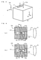
- FIG. 3 is a perspective view of the second embodiment of a flow cell according to the present invention
- FIG. 4 (a) is a sectional view seen from direction C of FIG 3
- FIG. 4 (b) is a sectional view seen from direction D of FIG. 3
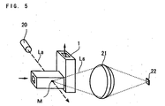
- FIG. 5 shows a schematic structure of a particle measuring apparatus according to the present invention.
- the flow cell 1 of the first embodiment is made of a transparent member, and provided with a passage 2 for flowing sample fluid therethrough in a direction of the arrow so as to form a particle monitoring area M with respect to laser light La, and another passage 3 having two exits at both ends which is perpendicular to the passage 2 and located between the passage 2 and a condenser lens L.
- the passage 2 is comprised of four inner walls 2a, 2b, 2c, and 2d, and the cross section is made rectangular.
- the passage 3 is also comprised of four inner walls 3a, 3b, 3c, and 3d, and the cross section is made rectangular.
- the particle monitoring area M is formed in a position where the four inner walls 2a, 2b, 2c, and 2d of the passage 2 do not hinder scattered light Ls from entering the outmost periphery portion of the condenser lens L for condensing the scattered light Ls so as to fully utilize the condensing angle of the condenser lens L.
- both ends of the passage 3 are opened, and thereby a portion of the inner wall c in the linear passage 100a shown in FIG. 6 (b) which limits the path of scattered light Ls is removed. Consequently, the scattered light Ls is not hindered from entering the outmost periphery portion of the condenser lens L.
- the distance between the inner wall 3c and the inner wall 3d is arranged to be greater than the distance between the inner wall 2c and the inner wall 2d so as not to hinder scattered light Ls from entering the outmost periphery portion of the condenser lens L by the inner walls 3c and 3d.
- scattered light Ls generated by particles contained in sample fluid passing through the particle monitoring area M can be condensed in a state where the condensing angle ⁇ of the condenser lens L is fully utilized
- both ends of the passage 3 are opened so as to form exits.
- the inner wall for closing the other end must be arranged so as not to hinder scattered light Ls from entering the outmost periphery portion of the condenser lens L.
- the flow cell 10 of the second embodiment is made of a transparent member, and provided with a passage 11 having a cross section of a rectangle shape, a passage 12 of a pyramidal shape, a passage 13 having a cross section of a rectangle shape, a passage 14 having a pyramidal shape, and a passage 15 having a cross section of a rectangle shape.
- the particle monitoring area M is formed within the passage 13 by irradiating sample fluid flowing through the passage 13 in a direction of the arrow with laser light La.
- the passage 13 is arranged to have a cross-sectional area and a length such that a particle monitoring area M having a desired size can be formed.
- the passages 11 and 15, and the passages 12 and 14 are positioned so as to be symmetrical with respect to the center of the passage 13, respectively.
- scattered light Ls generated by particles contained in sample fluid passing through the particle monitoring area M can be condensed in a state where the condensing angle ⁇ of the condenser lens L is fully utilized.
- the passages 12 and 14 are made in a pyramidal shape.
- a conical shape is also possible.
- another condenser lens may be provided in the opposite position with respect to the flow cell 10 so as to double the condensing angle ⁇ .
- portions of the flow cells 1 and 10 are made of a transparent material. It is possible to form the portions where light does not pass with a non-transparent material. In addition, it is not essential that the flow cells 1 and 10 are formed as a unitary member. The same function can be achieved by combing a plurality of members.
- the particle measuring apparatus is comprised of the flow cell 1, a laser light source 20, a condenser lens system 21 including the condenser lens L, and a photoelectric transducer element 22.
- the flow cell 10 shown in FIG. 3 can be used instead of the flow cell 1.
- the particle monitoring area M is formed by irradiating a predetermined area of the passage 2 of the flow cell 1 with laser light La from the laser light source 20.
- the optical axis of the laser light La is substantially perpendicular to the central axis of the passage 2 within the passage 2.
- the condenser lens system 21 has an optical axis which corresponds to the central axis of the passage 2, and condenses scattered light Ls generated by particles which has been irradiated with the laser light La in the particle monitoring area M. Incidentally, the condenser lens system 21 does not always need to be positioned in the central axis of the passage 2.
- the photoelectric transducer element 22 is provided in the optical axis of the condenser lens system 21, and receives the scattered light Ls which has been condensed by the condenser lens system 21 so as to transduce the scattered light Ls into voltage depending on the intensity.
- the condenser lens system 21 and subsequent elements are referred to as an optical detecting and processing means.
- a predetermined area of the passage 2 is irradiated with laser light La which has been emitted from the laser light source 20 so as to form a particle monitoring area M.
- the particles contained in sample fluid pass through the particle monitoring area M, the particles are irradiated with the laser light La and scattered light Ls is generated.
- the scattered light Ls is condensed by the condenser lens system 21 toward the photoelectric transducer element 22 in a state where the condensing angle of the condenser lens system 21 is fully utilized due to the shape of the passages 2 and 3.
- the scattered light Ls which has been condensed toward the photoelectric transducer element 22 is transduced into voltage depending on the intensity of the scattered light Ls.
- the detection level can be improved.
- scattered light generated by particles contained in sample fluid passing through the particle monitoring area can be condensed in a state where the condensing angle of the condenser means is fully utilized.
- the detection level can be improved.
Landscapes
- Chemical & Material Sciences (AREA)
- Dispersion Chemistry (AREA)
- Physics & Mathematics (AREA)
- Health & Medical Sciences (AREA)
- Life Sciences & Earth Sciences (AREA)
- Analytical Chemistry (AREA)
- Biochemistry (AREA)
- General Health & Medical Sciences (AREA)
- General Physics & Mathematics (AREA)
- Immunology (AREA)
- Pathology (AREA)
- Optical Measuring Cells (AREA)
- Investigating Or Analysing Materials By Optical Means (AREA)
Claims (3)
- Appareil de mesure de particules comprenant :une cuve de circulation (1) ayant un premier passage (2) et un second passage (3) s'étendant de manière continue à partir du premier passage ;une source de lumière (20) destinée à irradier un fluide d'échantillon s'écoulant à travers la cuve de circulation pour former une zone (M) de surveillance de particules,un condensateur (L), qui condense la lumière diffusée par des particules contenues dans le fluide d'échantillon passant à travers la zone de surveillance de particules afin d'obtenir des informations comprenant le diamètre des particules, dans lequel un axe central du premier passage correspond sensiblement à un axe optique du condensateur caractérisé en ce que la distance entre les parois internes du second passage (3c, 3d) soit ménagée pour être plus grande que la distance entre les parois internes du premier passage (2c, 2d) afin de ne pas empêcher la lumière diffusée d'entrer dans la partie la plus périphérique du condensateur.
- Appareil de mesure de particules selon la revendication 1,
dans lequel le second passage est sensiblement perpendiculaire au premier passage. - Appareil de mesure de particules selon la revendication 2,
dans lequel la coupe transversale du premier passage et du second passage est sensiblement de forme rectangulaire.
Applications Claiming Priority (1)
| Application Number | Priority Date | Filing Date | Title |
|---|---|---|---|
| PCT/JP2002/010104 WO2004029589A1 (fr) | 2002-09-27 | 2002-09-27 | Cuve a circulation et procede de mesure des particules utilisant cette cuve |
Publications (3)
| Publication Number | Publication Date |
|---|---|
| EP1544600A1 EP1544600A1 (fr) | 2005-06-22 |
| EP1544600A4 EP1544600A4 (fr) | 2008-09-10 |
| EP1544600B1 true EP1544600B1 (fr) | 2010-07-07 |
Family
ID=32040323
Family Applications (1)
| Application Number | Title | Priority Date | Filing Date |
|---|---|---|---|
| EP02775255A Expired - Lifetime EP1544600B1 (fr) | 2002-09-27 | 2002-09-27 | Cuve a circulation et procede de mesure des particules utilisant cette cuve |
Country Status (7)
| Country | Link |
|---|---|
| US (1) | US7170601B2 (fr) |
| EP (1) | EP1544600B1 (fr) |
| JP (1) | JP4050748B2 (fr) |
| CN (1) | CN100344956C (fr) |
| AU (1) | AU2002343929A1 (fr) |
| DE (1) | DE60236967D1 (fr) |
| WO (1) | WO2004029589A1 (fr) |
Families Citing this family (13)
| Publication number | Priority date | Publication date | Assignee | Title |
|---|---|---|---|---|
| EP1756547B1 (fr) * | 2004-03-01 | 2014-05-14 | Partec GmbH | Dispositif permettant de mesurer la lumiere emise par des cellules biologiques ou particules microscopiques |
| JP2007071794A (ja) * | 2005-09-09 | 2007-03-22 | Rion Co Ltd | 粒子検出器 |
| WO2008042199A2 (fr) | 2006-09-29 | 2008-04-10 | Cyberoptics Semiconductor, Inc. | Capteur de particules en forme de substrat |
| JP4389991B2 (ja) * | 2007-10-26 | 2009-12-24 | ソニー株式会社 | 微小粒子の光学的測定方法及び光学的測定装置 |
| JP5324598B2 (ja) | 2007-12-04 | 2013-10-23 | パーティクル・メージャーリング・システムズ・インコーポレーテッド | 非直角粒子検出システム及び方法 |
| TWI435080B (zh) | 2011-06-09 | 2014-04-21 | Univ Nat Pingtung Sci & Tech | 細胞或粒子檢測裝置 |
| CN107305177A (zh) * | 2016-04-21 | 2017-10-31 | 易幼文 | 一种微粒物可视化装置和便携式微粒物检测系统 |
| JP6549747B2 (ja) * | 2017-04-14 | 2019-07-24 | リオン株式会社 | 粒子測定装置および粒子測定方法 |
| JP7202904B2 (ja) * | 2019-01-24 | 2023-01-12 | リオン株式会社 | 粒子計数器 |
| JP7260308B2 (ja) * | 2019-01-24 | 2023-04-18 | リオン株式会社 | 流体中浮遊物質測定用フローセル及び粒子計数装置 |
| JP7339070B2 (ja) | 2019-08-29 | 2023-09-05 | リオン株式会社 | 生物粒子測定装置及び生物粒子測定方法 |
| US11442000B2 (en) * | 2019-12-16 | 2022-09-13 | Applied Materials, Inc. | In-situ, real-time detection of particulate defects in a fluid |
| DE102020001876A1 (de) * | 2020-03-23 | 2021-09-23 | Palas Gmbh Partikel- Und Lasermesstechnik | Verfahren und Aerosol-Messgerät zum Bestimmen der Partikelgeschwindigkeit eines Aerosols |
Family Cites Families (16)
| Publication number | Priority date | Publication date | Assignee | Title |
|---|---|---|---|---|
| BE793185A (fr) * | 1971-12-23 | 1973-04-16 | Atomic Energy Commission | Appareil pour analyser et trier rapidement des particules telles que des cellules biologiques |
| US4276475A (en) * | 1976-10-20 | 1981-06-30 | Waters Associates, Inc. | Novel photometric system |
| US4906094A (en) * | 1987-04-23 | 1990-03-06 | Sumitomo Chemical Co. Ltd. | Fine particle measuring method and system and a flow cell for use in the system |
| JPH0462455A (ja) * | 1990-06-29 | 1992-02-27 | Shimadzu Corp | 粒度分布測定装置 |
| JP2683172B2 (ja) * | 1991-10-01 | 1997-11-26 | キヤノン株式会社 | 検体測定方法及び検体測定装置 |
| JPH05240769A (ja) * | 1992-02-29 | 1993-09-17 | Horiba Ltd | 粒子計数装置 |
| US5371585A (en) * | 1992-11-10 | 1994-12-06 | Pacific Scientific Company | Particle detecting instrument with sapphire detecting cell defining a rectangular flow path |
| JP3328032B2 (ja) * | 1993-11-04 | 2002-09-24 | シスメックス株式会社 | 粒子分析装置 |
| JP3290786B2 (ja) * | 1993-11-26 | 2002-06-10 | シスメックス株式会社 | 粒子分析装置 |
| CN2251721Y (zh) * | 1995-08-28 | 1997-04-09 | 周定益 | 激光粒度测试仪 |
| KR100503020B1 (ko) * | 1997-03-10 | 2005-11-08 | 후지 덴키 가부시끼가이샤 | 탁도의측정방법및장치 |
| JPH1121165A (ja) * | 1997-06-30 | 1999-01-26 | Tokin Corp | フェライトコアの焼成方法及び焼成治具 |
| JP4026939B2 (ja) * | 1997-11-14 | 2007-12-26 | 日本分光株式会社 | Hplc用円二色性検出器 |
| JP3480669B2 (ja) | 1998-01-26 | 2003-12-22 | リオン株式会社 | 粒子通過位置検出装置 |
| JP3480670B2 (ja) * | 1998-01-28 | 2003-12-22 | リオン株式会社 | 光強度分布検出装置 |
| US6465802B1 (en) * | 1999-03-18 | 2002-10-15 | Rion Co., Ltd. | Particle measurement apparatus flow cell useful for sample fluids having different refractive indexes |
-
2002
- 2002-09-27 JP JP2004539450A patent/JP4050748B2/ja not_active Expired - Fee Related
- 2002-09-27 AU AU2002343929A patent/AU2002343929A1/en not_active Abandoned
- 2002-09-27 EP EP02775255A patent/EP1544600B1/fr not_active Expired - Lifetime
- 2002-09-27 CN CNB028296850A patent/CN100344956C/zh not_active Expired - Lifetime
- 2002-09-27 US US10/528,900 patent/US7170601B2/en not_active Expired - Lifetime
- 2002-09-27 WO PCT/JP2002/010104 patent/WO2004029589A1/fr active Application Filing
- 2002-09-27 DE DE60236967T patent/DE60236967D1/de not_active Expired - Lifetime
Also Published As
| Publication number | Publication date |
|---|---|
| CN100344956C (zh) | 2007-10-24 |
| US7170601B2 (en) | 2007-01-30 |
| JPWO2004029589A1 (ja) | 2006-01-26 |
| WO2004029589A1 (fr) | 2004-04-08 |
| DE60236967D1 (de) | 2010-08-19 |
| EP1544600A4 (fr) | 2008-09-10 |
| US20060001874A1 (en) | 2006-01-05 |
| JP4050748B2 (ja) | 2008-02-20 |
| CN1668910A (zh) | 2005-09-14 |
| EP1544600A1 (fr) | 2005-06-22 |
| AU2002343929A1 (en) | 2004-04-19 |
Similar Documents
| Publication | Publication Date | Title |
|---|---|---|
| EP1544600B1 (fr) | Cuve a circulation et procede de mesure des particules utilisant cette cuve | |
| US9134230B2 (en) | Microbial detection apparatus and method | |
| US7492522B2 (en) | Optical detector for a particle sorting system | |
| CA1117310A (fr) | Cellule parabolique d'analyse | |
| US7916293B2 (en) | Non-orthogonal particle detection systems and methods | |
| US7479625B2 (en) | Sensing photons from object in channels | |
| US7386199B2 (en) | Providing light to channels or portions | |
| KR102644216B1 (ko) | 입자 센싱 장치 | |
| JP4064445B1 (ja) | 粒子測定装置 | |
| JP4763159B2 (ja) | フローサイトメータ | |
| US20020030815A1 (en) | Light scattering type particle detector | |
| KR100860933B1 (ko) | 플로우 셀 및 이를 이용한 입자측정장치 | |
| EP3615915B1 (fr) | Détection latérale des propriétés d'un fluide | |
| JP2004361239A (ja) | マイクロ分析システム用光学系 | |
| JP3966851B2 (ja) | 光散乱式粒子計数装置 | |
| JPH08178831A (ja) | 光散乱式粒子検出装置 | |
| JPS59102139A (ja) | 血球カウンタ | |
| JP2000266661A (ja) | フローセル及びこのフローセルを用いた粒子測定装置 | |
| JPH0736051U (ja) | ガス分析計 | |
| Azmayesh-Fard et al. | A dynamic strategy for wavelength sensing using the diffracted orders of a grating | |
| KR0125916B1 (ko) | 휴대용 입자 분석기 | |
| JP2021056126A (ja) | 生体粒子分析用マイクロチップ、生体粒子分析装置、微小粒子分析用マイクロチップ、及び微小粒子分析装置 | |
| CN112673247A (zh) | 用于流式细胞术中的离轴照射的系统、设备以及方法 | |
| KR20200027251A (ko) | 혈구 분석 장치, 이를 이용한 혈구 분석 방법 | |
| SE429479B (sv) | Flodescell |
Legal Events
| Date | Code | Title | Description |
|---|---|---|---|
| PUAI | Public reference made under article 153(3) epc to a published international application that has entered the european phase |
Free format text: ORIGINAL CODE: 0009012 |
|
| 17P | Request for examination filed |
Effective date: 20050316 |
|
| AK | Designated contracting states |
Kind code of ref document: A1 Designated state(s): AT BE BG CH CY CZ DE DK EE ES FI FR GB GR IE IT LI LU MC NL PT SE SK TR |
|
| AX | Request for extension of the european patent |
Extension state: AL LT LV MK RO SI |
|
| DAX | Request for extension of the european patent (deleted) | ||
| RBV | Designated contracting states (corrected) |
Designated state(s): DE FR |
|
| A4 | Supplementary search report drawn up and despatched |
Effective date: 20080813 |
|
| 17Q | First examination report despatched |
Effective date: 20090324 |
|
| GRAP | Despatch of communication of intention to grant a patent |
Free format text: ORIGINAL CODE: EPIDOSNIGR1 |
|
| GRAS | Grant fee paid |
Free format text: ORIGINAL CODE: EPIDOSNIGR3 |
|
| GRAA | (expected) grant |
Free format text: ORIGINAL CODE: 0009210 |
|
| AK | Designated contracting states |
Kind code of ref document: B1 Designated state(s): DE FR |
|
| REF | Corresponds to: |
Ref document number: 60236967 Country of ref document: DE Date of ref document: 20100819 Kind code of ref document: P |
|
| PLBE | No opposition filed within time limit |
Free format text: ORIGINAL CODE: 0009261 |
|
| STAA | Information on the status of an ep patent application or granted ep patent |
Free format text: STATUS: NO OPPOSITION FILED WITHIN TIME LIMIT |
|
| 26N | No opposition filed |
Effective date: 20110408 |
|
| REG | Reference to a national code |
Ref country code: FR Ref legal event code: ST Effective date: 20110531 |
|
| REG | Reference to a national code |
Ref country code: DE Ref legal event code: R097 Ref document number: 60236967 Country of ref document: DE Effective date: 20110408 |
|
| PG25 | Lapsed in a contracting state [announced via postgrant information from national office to epo] |
Ref country code: FR Free format text: LAPSE BECAUSE OF NON-PAYMENT OF DUE FEES Effective date: 20100930 |
|
| PGFP | Annual fee paid to national office [announced via postgrant information from national office to epo] |
Ref country code: DE Payment date: 20210920 Year of fee payment: 20 |
|
| REG | Reference to a national code |
Ref country code: DE Ref legal event code: R071 Ref document number: 60236967 Country of ref document: DE |