EP1544428A1 - Apparatus and method for clarifying exhaust gas of diesel engine - Google Patents
Apparatus and method for clarifying exhaust gas of diesel engine Download PDFInfo
- Publication number
- EP1544428A1 EP1544428A1 EP03792839A EP03792839A EP1544428A1 EP 1544428 A1 EP1544428 A1 EP 1544428A1 EP 03792839 A EP03792839 A EP 03792839A EP 03792839 A EP03792839 A EP 03792839A EP 1544428 A1 EP1544428 A1 EP 1544428A1
- Authority
- EP
- European Patent Office
- Prior art keywords
- exhaust gas
- nox
- diesel engine
- temperature
- catalyst
- Prior art date
- Legal status (The legal status is an assumption and is not a legal conclusion. Google has not performed a legal analysis and makes no representation as to the accuracy of the status listed.)
- Withdrawn
Links
Images


Classifications
-
- F—MECHANICAL ENGINEERING; LIGHTING; HEATING; WEAPONS; BLASTING
- F02—COMBUSTION ENGINES; HOT-GAS OR COMBUSTION-PRODUCT ENGINE PLANTS
- F02D—CONTROLLING COMBUSTION ENGINES
- F02D41/00—Electrical control of supply of combustible mixture or its constituents
- F02D41/30—Controlling fuel injection
- F02D41/3011—Controlling fuel injection according to or using specific or several modes of combustion
-
- F—MECHANICAL ENGINEERING; LIGHTING; HEATING; WEAPONS; BLASTING
- F01—MACHINES OR ENGINES IN GENERAL; ENGINE PLANTS IN GENERAL; STEAM ENGINES
- F01N—GAS-FLOW SILENCERS OR EXHAUST APPARATUS FOR MACHINES OR ENGINES IN GENERAL; GAS-FLOW SILENCERS OR EXHAUST APPARATUS FOR INTERNAL COMBUSTION ENGINES
- F01N13/00—Exhaust or silencing apparatus characterised by constructional features ; Exhaust or silencing apparatus, or parts thereof, having pertinent characteristics not provided for in, or of interest apart from, groups F01N1/00 - F01N5/00, F01N9/00, F01N11/00
- F01N13/009—Exhaust or silencing apparatus characterised by constructional features ; Exhaust or silencing apparatus, or parts thereof, having pertinent characteristics not provided for in, or of interest apart from, groups F01N1/00 - F01N5/00, F01N9/00, F01N11/00 having two or more separate purifying devices arranged in series
- F01N13/0097—Exhaust or silencing apparatus characterised by constructional features ; Exhaust or silencing apparatus, or parts thereof, having pertinent characteristics not provided for in, or of interest apart from, groups F01N1/00 - F01N5/00, F01N9/00, F01N11/00 having two or more separate purifying devices arranged in series the purifying devices are arranged in a single housing
-
- F—MECHANICAL ENGINEERING; LIGHTING; HEATING; WEAPONS; BLASTING
- F01—MACHINES OR ENGINES IN GENERAL; ENGINE PLANTS IN GENERAL; STEAM ENGINES
- F01N—GAS-FLOW SILENCERS OR EXHAUST APPARATUS FOR MACHINES OR ENGINES IN GENERAL; GAS-FLOW SILENCERS OR EXHAUST APPARATUS FOR INTERNAL COMBUSTION ENGINES
- F01N3/00—Exhaust or silencing apparatus having means for purifying, rendering innocuous, or otherwise treating exhaust
- F01N3/02—Exhaust or silencing apparatus having means for purifying, rendering innocuous, or otherwise treating exhaust for cooling, or for removing solid constituents of, exhaust
- F01N3/021—Exhaust or silencing apparatus having means for purifying, rendering innocuous, or otherwise treating exhaust for cooling, or for removing solid constituents of, exhaust by means of filters
- F01N3/023—Exhaust or silencing apparatus having means for purifying, rendering innocuous, or otherwise treating exhaust for cooling, or for removing solid constituents of, exhaust by means of filters using means for regenerating the filters, e.g. by burning trapped particles
- F01N3/027—Exhaust or silencing apparatus having means for purifying, rendering innocuous, or otherwise treating exhaust for cooling, or for removing solid constituents of, exhaust by means of filters using means for regenerating the filters, e.g. by burning trapped particles using electric or magnetic heating means
-
- F—MECHANICAL ENGINEERING; LIGHTING; HEATING; WEAPONS; BLASTING
- F01—MACHINES OR ENGINES IN GENERAL; ENGINE PLANTS IN GENERAL; STEAM ENGINES
- F01N—GAS-FLOW SILENCERS OR EXHAUST APPARATUS FOR MACHINES OR ENGINES IN GENERAL; GAS-FLOW SILENCERS OR EXHAUST APPARATUS FOR INTERNAL COMBUSTION ENGINES
- F01N3/00—Exhaust or silencing apparatus having means for purifying, rendering innocuous, or otherwise treating exhaust
- F01N3/08—Exhaust or silencing apparatus having means for purifying, rendering innocuous, or otherwise treating exhaust for rendering innocuous
- F01N3/0807—Exhaust or silencing apparatus having means for purifying, rendering innocuous, or otherwise treating exhaust for rendering innocuous by using absorbents or adsorbents
- F01N3/0828—Exhaust or silencing apparatus having means for purifying, rendering innocuous, or otherwise treating exhaust for rendering innocuous by using absorbents or adsorbents characterised by the absorbed or adsorbed substances
- F01N3/0835—Hydrocarbons
-
- F—MECHANICAL ENGINEERING; LIGHTING; HEATING; WEAPONS; BLASTING
- F01—MACHINES OR ENGINES IN GENERAL; ENGINE PLANTS IN GENERAL; STEAM ENGINES
- F01N—GAS-FLOW SILENCERS OR EXHAUST APPARATUS FOR MACHINES OR ENGINES IN GENERAL; GAS-FLOW SILENCERS OR EXHAUST APPARATUS FOR INTERNAL COMBUSTION ENGINES
- F01N3/00—Exhaust or silencing apparatus having means for purifying, rendering innocuous, or otherwise treating exhaust
- F01N3/08—Exhaust or silencing apparatus having means for purifying, rendering innocuous, or otherwise treating exhaust for rendering innocuous
- F01N3/0807—Exhaust or silencing apparatus having means for purifying, rendering innocuous, or otherwise treating exhaust for rendering innocuous by using absorbents or adsorbents
- F01N3/0828—Exhaust or silencing apparatus having means for purifying, rendering innocuous, or otherwise treating exhaust for rendering innocuous by using absorbents or adsorbents characterised by the absorbed or adsorbed substances
- F01N3/0842—Nitrogen oxides
-
- F—MECHANICAL ENGINEERING; LIGHTING; HEATING; WEAPONS; BLASTING
- F01—MACHINES OR ENGINES IN GENERAL; ENGINE PLANTS IN GENERAL; STEAM ENGINES
- F01N—GAS-FLOW SILENCERS OR EXHAUST APPARATUS FOR MACHINES OR ENGINES IN GENERAL; GAS-FLOW SILENCERS OR EXHAUST APPARATUS FOR INTERNAL COMBUSTION ENGINES
- F01N3/00—Exhaust or silencing apparatus having means for purifying, rendering innocuous, or otherwise treating exhaust
- F01N3/08—Exhaust or silencing apparatus having means for purifying, rendering innocuous, or otherwise treating exhaust for rendering innocuous
- F01N3/10—Exhaust or silencing apparatus having means for purifying, rendering innocuous, or otherwise treating exhaust for rendering innocuous by thermal or catalytic conversion of noxious components of exhaust
- F01N3/103—Oxidation catalysts for HC and CO only
-
- F—MECHANICAL ENGINEERING; LIGHTING; HEATING; WEAPONS; BLASTING
- F01—MACHINES OR ENGINES IN GENERAL; ENGINE PLANTS IN GENERAL; STEAM ENGINES
- F01N—GAS-FLOW SILENCERS OR EXHAUST APPARATUS FOR MACHINES OR ENGINES IN GENERAL; GAS-FLOW SILENCERS OR EXHAUST APPARATUS FOR INTERNAL COMBUSTION ENGINES
- F01N9/00—Electrical control of exhaust gas treating apparatus
- F01N9/002—Electrical control of exhaust gas treating apparatus of filter regeneration, e.g. detection of clogging
-
- F—MECHANICAL ENGINEERING; LIGHTING; HEATING; WEAPONS; BLASTING
- F02—COMBUSTION ENGINES; HOT-GAS OR COMBUSTION-PRODUCT ENGINE PLANTS
- F02D—CONTROLLING COMBUSTION ENGINES
- F02D41/00—Electrical control of supply of combustible mixture or its constituents
- F02D41/02—Circuit arrangements for generating control signals
- F02D41/021—Introducing corrections for particular conditions exterior to the engine
- F02D41/0235—Introducing corrections for particular conditions exterior to the engine in relation with the state of the exhaust gas treating apparatus
- F02D41/024—Introducing corrections for particular conditions exterior to the engine in relation with the state of the exhaust gas treating apparatus to increase temperature of the exhaust gas treating apparatus
- F02D41/0245—Introducing corrections for particular conditions exterior to the engine in relation with the state of the exhaust gas treating apparatus to increase temperature of the exhaust gas treating apparatus by increasing temperature of the exhaust gas leaving the engine
-
- F—MECHANICAL ENGINEERING; LIGHTING; HEATING; WEAPONS; BLASTING
- F02—COMBUSTION ENGINES; HOT-GAS OR COMBUSTION-PRODUCT ENGINE PLANTS
- F02D—CONTROLLING COMBUSTION ENGINES
- F02D41/00—Electrical control of supply of combustible mixture or its constituents
- F02D41/02—Circuit arrangements for generating control signals
- F02D41/021—Introducing corrections for particular conditions exterior to the engine
- F02D41/0235—Introducing corrections for particular conditions exterior to the engine in relation with the state of the exhaust gas treating apparatus
- F02D41/027—Introducing corrections for particular conditions exterior to the engine in relation with the state of the exhaust gas treating apparatus to purge or regenerate the exhaust gas treating apparatus
- F02D41/0275—Introducing corrections for particular conditions exterior to the engine in relation with the state of the exhaust gas treating apparatus to purge or regenerate the exhaust gas treating apparatus the exhaust gas treating apparatus being a NOx trap or adsorbent
-
- F—MECHANICAL ENGINEERING; LIGHTING; HEATING; WEAPONS; BLASTING
- F02—COMBUSTION ENGINES; HOT-GAS OR COMBUSTION-PRODUCT ENGINE PLANTS
- F02D—CONTROLLING COMBUSTION ENGINES
- F02D41/00—Electrical control of supply of combustible mixture or its constituents
- F02D41/02—Circuit arrangements for generating control signals
- F02D41/021—Introducing corrections for particular conditions exterior to the engine
- F02D41/0235—Introducing corrections for particular conditions exterior to the engine in relation with the state of the exhaust gas treating apparatus
- F02D41/027—Introducing corrections for particular conditions exterior to the engine in relation with the state of the exhaust gas treating apparatus to purge or regenerate the exhaust gas treating apparatus
- F02D41/029—Introducing corrections for particular conditions exterior to the engine in relation with the state of the exhaust gas treating apparatus to purge or regenerate the exhaust gas treating apparatus the exhaust gas treating apparatus being a particulate filter
-
- F—MECHANICAL ENGINEERING; LIGHTING; HEATING; WEAPONS; BLASTING
- F01—MACHINES OR ENGINES IN GENERAL; ENGINE PLANTS IN GENERAL; STEAM ENGINES
- F01N—GAS-FLOW SILENCERS OR EXHAUST APPARATUS FOR MACHINES OR ENGINES IN GENERAL; GAS-FLOW SILENCERS OR EXHAUST APPARATUS FOR INTERNAL COMBUSTION ENGINES
- F01N2240/00—Combination or association of two or more different exhaust treating devices, or of at least one such device with an auxiliary device, not covered by indexing codes F01N2230/00 or F01N2250/00, one of the devices being
- F01N2240/16—Combination or association of two or more different exhaust treating devices, or of at least one such device with an auxiliary device, not covered by indexing codes F01N2230/00 or F01N2250/00, one of the devices being an electric heater, i.e. a resistance heater
-
- F—MECHANICAL ENGINEERING; LIGHTING; HEATING; WEAPONS; BLASTING
- F01—MACHINES OR ENGINES IN GENERAL; ENGINE PLANTS IN GENERAL; STEAM ENGINES
- F01N—GAS-FLOW SILENCERS OR EXHAUST APPARATUS FOR MACHINES OR ENGINES IN GENERAL; GAS-FLOW SILENCERS OR EXHAUST APPARATUS FOR INTERNAL COMBUSTION ENGINES
- F01N2250/00—Combinations of different methods of purification
- F01N2250/02—Combinations of different methods of purification filtering and catalytic conversion
-
- F—MECHANICAL ENGINEERING; LIGHTING; HEATING; WEAPONS; BLASTING
- F01—MACHINES OR ENGINES IN GENERAL; ENGINE PLANTS IN GENERAL; STEAM ENGINES
- F01N—GAS-FLOW SILENCERS OR EXHAUST APPARATUS FOR MACHINES OR ENGINES IN GENERAL; GAS-FLOW SILENCERS OR EXHAUST APPARATUS FOR INTERNAL COMBUSTION ENGINES
- F01N2250/00—Combinations of different methods of purification
- F01N2250/12—Combinations of different methods of purification absorption or adsorption, and catalytic conversion
-
- F—MECHANICAL ENGINEERING; LIGHTING; HEATING; WEAPONS; BLASTING
- F01—MACHINES OR ENGINES IN GENERAL; ENGINE PLANTS IN GENERAL; STEAM ENGINES
- F01N—GAS-FLOW SILENCERS OR EXHAUST APPARATUS FOR MACHINES OR ENGINES IN GENERAL; GAS-FLOW SILENCERS OR EXHAUST APPARATUS FOR INTERNAL COMBUSTION ENGINES
- F01N2250/00—Combinations of different methods of purification
- F01N2250/14—Combinations of different methods of purification absorption or adsorption, and filtering
-
- F—MECHANICAL ENGINEERING; LIGHTING; HEATING; WEAPONS; BLASTING
- F01—MACHINES OR ENGINES IN GENERAL; ENGINE PLANTS IN GENERAL; STEAM ENGINES
- F01N—GAS-FLOW SILENCERS OR EXHAUST APPARATUS FOR MACHINES OR ENGINES IN GENERAL; GAS-FLOW SILENCERS OR EXHAUST APPARATUS FOR INTERNAL COMBUSTION ENGINES
- F01N2430/00—Influencing exhaust purification, e.g. starting of catalytic reaction, filter regeneration, or the like, by controlling engine operating characteristics
- F01N2430/06—Influencing exhaust purification, e.g. starting of catalytic reaction, filter regeneration, or the like, by controlling engine operating characteristics by varying fuel-air ratio, e.g. by enriching fuel-air mixture
-
- F—MECHANICAL ENGINEERING; LIGHTING; HEATING; WEAPONS; BLASTING
- F01—MACHINES OR ENGINES IN GENERAL; ENGINE PLANTS IN GENERAL; STEAM ENGINES
- F01N—GAS-FLOW SILENCERS OR EXHAUST APPARATUS FOR MACHINES OR ENGINES IN GENERAL; GAS-FLOW SILENCERS OR EXHAUST APPARATUS FOR INTERNAL COMBUSTION ENGINES
- F01N2430/00—Influencing exhaust purification, e.g. starting of catalytic reaction, filter regeneration, or the like, by controlling engine operating characteristics
- F01N2430/08—Influencing exhaust purification, e.g. starting of catalytic reaction, filter regeneration, or the like, by controlling engine operating characteristics by modifying ignition or injection timing
- F01N2430/085—Influencing exhaust purification, e.g. starting of catalytic reaction, filter regeneration, or the like, by controlling engine operating characteristics by modifying ignition or injection timing at least a part of the injection taking place during expansion or exhaust stroke
-
- F—MECHANICAL ENGINEERING; LIGHTING; HEATING; WEAPONS; BLASTING
- F01—MACHINES OR ENGINES IN GENERAL; ENGINE PLANTS IN GENERAL; STEAM ENGINES
- F01N—GAS-FLOW SILENCERS OR EXHAUST APPARATUS FOR MACHINES OR ENGINES IN GENERAL; GAS-FLOW SILENCERS OR EXHAUST APPARATUS FOR INTERNAL COMBUSTION ENGINES
- F01N2570/00—Exhaust treating apparatus eliminating, absorbing or adsorbing specific elements or compounds
- F01N2570/14—Nitrogen oxides
-
- F—MECHANICAL ENGINEERING; LIGHTING; HEATING; WEAPONS; BLASTING
- F01—MACHINES OR ENGINES IN GENERAL; ENGINE PLANTS IN GENERAL; STEAM ENGINES
- F01N—GAS-FLOW SILENCERS OR EXHAUST APPARATUS FOR MACHINES OR ENGINES IN GENERAL; GAS-FLOW SILENCERS OR EXHAUST APPARATUS FOR INTERNAL COMBUSTION ENGINES
- F01N3/00—Exhaust or silencing apparatus having means for purifying, rendering innocuous, or otherwise treating exhaust
- F01N3/08—Exhaust or silencing apparatus having means for purifying, rendering innocuous, or otherwise treating exhaust for rendering innocuous
- F01N3/0807—Exhaust or silencing apparatus having means for purifying, rendering innocuous, or otherwise treating exhaust for rendering innocuous by using absorbents or adsorbents
- F01N3/0814—Exhaust or silencing apparatus having means for purifying, rendering innocuous, or otherwise treating exhaust for rendering innocuous by using absorbents or adsorbents combined with catalytic converters, e.g. NOx absorption/storage reduction catalysts
-
- F—MECHANICAL ENGINEERING; LIGHTING; HEATING; WEAPONS; BLASTING
- F01—MACHINES OR ENGINES IN GENERAL; ENGINE PLANTS IN GENERAL; STEAM ENGINES
- F01N—GAS-FLOW SILENCERS OR EXHAUST APPARATUS FOR MACHINES OR ENGINES IN GENERAL; GAS-FLOW SILENCERS OR EXHAUST APPARATUS FOR INTERNAL COMBUSTION ENGINES
- F01N3/00—Exhaust or silencing apparatus having means for purifying, rendering innocuous, or otherwise treating exhaust
- F01N3/08—Exhaust or silencing apparatus having means for purifying, rendering innocuous, or otherwise treating exhaust for rendering innocuous
- F01N3/0807—Exhaust or silencing apparatus having means for purifying, rendering innocuous, or otherwise treating exhaust for rendering innocuous by using absorbents or adsorbents
- F01N3/0821—Exhaust or silencing apparatus having means for purifying, rendering innocuous, or otherwise treating exhaust for rendering innocuous by using absorbents or adsorbents combined with particulate filters
-
- F—MECHANICAL ENGINEERING; LIGHTING; HEATING; WEAPONS; BLASTING
- F02—COMBUSTION ENGINES; HOT-GAS OR COMBUSTION-PRODUCT ENGINE PLANTS
- F02D—CONTROLLING COMBUSTION ENGINES
- F02D41/00—Electrical control of supply of combustible mixture or its constituents
- F02D41/0025—Controlling engines characterised by use of non-liquid fuels, pluralities of fuels, or non-fuel substances added to the combustible mixtures
- F02D41/0047—Controlling exhaust gas recirculation [EGR]
- F02D41/0065—Specific aspects of external EGR control
- F02D2041/0067—Determining the EGR temperature
-
- F—MECHANICAL ENGINEERING; LIGHTING; HEATING; WEAPONS; BLASTING
- F02—COMBUSTION ENGINES; HOT-GAS OR COMBUSTION-PRODUCT ENGINE PLANTS
- F02D—CONTROLLING COMBUSTION ENGINES
- F02D2200/00—Input parameters for engine control
- F02D2200/02—Input parameters for engine control the parameters being related to the engine
- F02D2200/08—Exhaust gas treatment apparatus parameters
- F02D2200/0802—Temperature of the exhaust gas treatment apparatus
-
- F—MECHANICAL ENGINEERING; LIGHTING; HEATING; WEAPONS; BLASTING
- F02—COMBUSTION ENGINES; HOT-GAS OR COMBUSTION-PRODUCT ENGINE PLANTS
- F02D—CONTROLLING COMBUSTION ENGINES
- F02D2200/00—Input parameters for engine control
- F02D2200/02—Input parameters for engine control the parameters being related to the engine
- F02D2200/08—Exhaust gas treatment apparatus parameters
- F02D2200/0806—NOx storage amount, i.e. amount of NOx stored on NOx trap
-
- F—MECHANICAL ENGINEERING; LIGHTING; HEATING; WEAPONS; BLASTING
- F02—COMBUSTION ENGINES; HOT-GAS OR COMBUSTION-PRODUCT ENGINE PLANTS
- F02D—CONTROLLING COMBUSTION ENGINES
- F02D2200/00—Input parameters for engine control
- F02D2200/02—Input parameters for engine control the parameters being related to the engine
- F02D2200/08—Exhaust gas treatment apparatus parameters
- F02D2200/0812—Particle filter loading
-
- F—MECHANICAL ENGINEERING; LIGHTING; HEATING; WEAPONS; BLASTING
- F02—COMBUSTION ENGINES; HOT-GAS OR COMBUSTION-PRODUCT ENGINE PLANTS
- F02D—CONTROLLING COMBUSTION ENGINES
- F02D41/00—Electrical control of supply of combustible mixture or its constituents
- F02D41/02—Circuit arrangements for generating control signals
- F02D41/14—Introducing closed-loop corrections
- F02D41/1438—Introducing closed-loop corrections using means for determining characteristics of the combustion gases; Sensors therefor
- F02D41/1439—Introducing closed-loop corrections using means for determining characteristics of the combustion gases; Sensors therefor characterised by the position of the sensor
- F02D41/1441—Plural sensors
-
- F—MECHANICAL ENGINEERING; LIGHTING; HEATING; WEAPONS; BLASTING
- F02—COMBUSTION ENGINES; HOT-GAS OR COMBUSTION-PRODUCT ENGINE PLANTS
- F02D—CONTROLLING COMBUSTION ENGINES
- F02D41/00—Electrical control of supply of combustible mixture or its constituents
- F02D41/02—Circuit arrangements for generating control signals
- F02D41/14—Introducing closed-loop corrections
- F02D41/1438—Introducing closed-loop corrections using means for determining characteristics of the combustion gases; Sensors therefor
- F02D41/1444—Introducing closed-loop corrections using means for determining characteristics of the combustion gases; Sensors therefor characterised by the characteristics of the combustion gases
- F02D41/1446—Introducing closed-loop corrections using means for determining characteristics of the combustion gases; Sensors therefor characterised by the characteristics of the combustion gases the characteristics being exhaust temperatures
-
- F—MECHANICAL ENGINEERING; LIGHTING; HEATING; WEAPONS; BLASTING
- F02—COMBUSTION ENGINES; HOT-GAS OR COMBUSTION-PRODUCT ENGINE PLANTS
- F02D—CONTROLLING COMBUSTION ENGINES
- F02D41/00—Electrical control of supply of combustible mixture or its constituents
- F02D41/02—Circuit arrangements for generating control signals
- F02D41/14—Introducing closed-loop corrections
- F02D41/1438—Introducing closed-loop corrections using means for determining characteristics of the combustion gases; Sensors therefor
- F02D41/1444—Introducing closed-loop corrections using means for determining characteristics of the combustion gases; Sensors therefor characterised by the characteristics of the combustion gases
- F02D41/1454—Introducing closed-loop corrections using means for determining characteristics of the combustion gases; Sensors therefor characterised by the characteristics of the combustion gases the characteristics being an oxygen content or concentration or the air-fuel ratio
-
- F—MECHANICAL ENGINEERING; LIGHTING; HEATING; WEAPONS; BLASTING
- F02—COMBUSTION ENGINES; HOT-GAS OR COMBUSTION-PRODUCT ENGINE PLANTS
- F02D—CONTROLLING COMBUSTION ENGINES
- F02D41/00—Electrical control of supply of combustible mixture or its constituents
- F02D41/02—Circuit arrangements for generating control signals
- F02D41/18—Circuit arrangements for generating control signals by measuring intake air flow
- F02D41/187—Circuit arrangements for generating control signals by measuring intake air flow using a hot wire flow sensor
-
- Y—GENERAL TAGGING OF NEW TECHNOLOGICAL DEVELOPMENTS; GENERAL TAGGING OF CROSS-SECTIONAL TECHNOLOGIES SPANNING OVER SEVERAL SECTIONS OF THE IPC; TECHNICAL SUBJECTS COVERED BY FORMER USPC CROSS-REFERENCE ART COLLECTIONS [XRACs] AND DIGESTS
- Y02—TECHNOLOGIES OR APPLICATIONS FOR MITIGATION OR ADAPTATION AGAINST CLIMATE CHANGE
- Y02A—TECHNOLOGIES FOR ADAPTATION TO CLIMATE CHANGE
- Y02A50/00—TECHNOLOGIES FOR ADAPTATION TO CLIMATE CHANGE in human health protection, e.g. against extreme weather
- Y02A50/20—Air quality improvement or preservation, e.g. vehicle emission control or emission reduction by using catalytic converters
-
- Y—GENERAL TAGGING OF NEW TECHNOLOGICAL DEVELOPMENTS; GENERAL TAGGING OF CROSS-SECTIONAL TECHNOLOGIES SPANNING OVER SEVERAL SECTIONS OF THE IPC; TECHNICAL SUBJECTS COVERED BY FORMER USPC CROSS-REFERENCE ART COLLECTIONS [XRACs] AND DIGESTS
- Y02—TECHNOLOGIES OR APPLICATIONS FOR MITIGATION OR ADAPTATION AGAINST CLIMATE CHANGE
- Y02T—CLIMATE CHANGE MITIGATION TECHNOLOGIES RELATED TO TRANSPORTATION
- Y02T10/00—Road transport of goods or passengers
- Y02T10/10—Internal combustion engine [ICE] based vehicles
- Y02T10/12—Improving ICE efficiencies
-
- Y—GENERAL TAGGING OF NEW TECHNOLOGICAL DEVELOPMENTS; GENERAL TAGGING OF CROSS-SECTIONAL TECHNOLOGIES SPANNING OVER SEVERAL SECTIONS OF THE IPC; TECHNICAL SUBJECTS COVERED BY FORMER USPC CROSS-REFERENCE ART COLLECTIONS [XRACs] AND DIGESTS
- Y02—TECHNOLOGIES OR APPLICATIONS FOR MITIGATION OR ADAPTATION AGAINST CLIMATE CHANGE
- Y02T—CLIMATE CHANGE MITIGATION TECHNOLOGIES RELATED TO TRANSPORTATION
- Y02T10/00—Road transport of goods or passengers
- Y02T10/10—Internal combustion engine [ICE] based vehicles
- Y02T10/40—Engine management systems
Definitions
- the present invention relates to an apparatus and a method for purifying (clarifying) an exhaust gas of a diesel engine, and, more particularly, relates to an exhaust gas purifying apparatus and an exhaust gas purifying method that are used in vehicles such as automobiles, and purify an exhaust gas exhausted from the diesel engine for the purpose of preventing air pollution.
- exhaust gas components such as nitrogen oxides (NOx), particulate matters (PM), hydrocarbon (HC), and carbon monoxide (CO) are subject to the exhaust emission control of a diesel engine.
- NOx nitrogen oxides
- PM particulate matters
- HC hydrocarbon
- CO carbon monoxide
- Main components of the PM are soot, that is, carbon (C), hydrocarbon, soluble organic fraction (SOF), and sulfur content.
- C carbon
- SOF soluble organic fraction
- an exhaust gas purifying apparatus for a diesel engine in which, on the way of an exhaust route of the diesel engine, an oxidation catalyst, a diesel particulate filter (DPF) that collects the particulate matters in an exhaust gas, and an NOx catalyst are provided from the upstream side, toward a flow of the exhaust gas, and, furthermore, a fuel addition apparatus (fuel addition nozzle) that injects an additive (fuel) for reducing NOx in the exhaust gas is provided between the diesel particulate filter (DPF) and the NOx catalyst.
- a fuel addition apparatus fuel addition nozzle
- an exhaust gas purifying apparatus for a diesel engine in which, on the way of an exhaust route of the diesel engine, an NOx catalyst, an oxidation catalyst, and a particulate filter are provided sequentially from the upstream side, toward a flow of an exhaust gas, and an addition apparatus that injects an additive for reducing NOx in the exhaust gas is provided on the upstream side of the NOx catalyst, then, based on information about detection from the amount of accumulation detector that detects the amount of particulate matters accumulated in the particulate filter, the additive is injected from the addition apparatus when the amount of accumulation of particulate matters is below a fixed value.
- JP-A No. 119444/1995 of the Japanese Laid-Open Patent Publication JP-A No. 295243/2002 of the Japanese Laid-Open Patent Publication, JP-A No. 349236/2002 of the Japanese Laid-Open Patent Publication, and JP-A No.
- an exhaust gas purifying apparatus in which an NOx catalyst and a particulate filter are provided sequentially from the upstream side, toward a flow of an exhaust gas, on the way of an exhaust route of a diesel engine, and fuel injection nozzle that injects an additive (fuel) for reducing NOx in the exhaust gas is provided on the upstream side of the NOx catalyst, or a copper-zeolite catalyst, a platinum catalyst, and the particulate filter are provided sequentially from the upstream side, toward the flow of the exhaust gas, on the way of the exhaust route of the diesel engine, and the fuel injection nozzle that injects the additive (fuel) for reducing the NOx in the exhaust gas is provided on the upstream side of the copper-zeolite catalyst.
- an exhaust gas purifying apparatus in which an NOx catalyst and a particulate filter are provided sequentially from the upstream side, toward a flow of an exhaust gas on the way of an exhaust route of the diesel engine, and that supplies the exhaust gas with fuel that is a reducing agent necessary for reducing NOx by performing a fuel secondary injection (post injection) that injects the fuel to an engine combustion chamber in the expansion stroke or the exhaust stroke, apart from a main injection in the compression stroke of the diesel engine.
- a fuel secondary injection post injection
- NOx catalysts used in an exhaust gas purifying apparatus many NOx catalysts are adopted in which an NOx absorbent having capability of absorbing (occluding) NOx in an oxygen presence atmosphere, and a precious metal catalyst having capability of oxidizing hydrocarbon, in other words, a catalyst having capability of reducing and purifying the occluded NOx in an excess fuel atmosphere are supported together in a honeycomb structure (carrier) of porous ceramics.
- an alkali metal such as Li, Na, K, or Cs, or an alkali earth metal such as Mg, Ca, or Ba, or a rare earth metal such as Y, La, Ce, Pr, Eu, Nd, or Dy, is enumerated as the NOx absorbent, and Pt is enumerated as the precious metal catalyst.
- the foregoing NOx catalyst used in the conventional exhaust gas purifying apparatus is an occlusion type NOx catalyst that absorbs and captures NOx in a NOx absorbent as a compound.
- NOx absorbent NOx scavenger
- NO is BaO
- NO is oxidized to NO 2 (refer to a formula (1)).
- the NO is absorbed (occluded) in the NOx absorbent using the NOx as a nitric compound Ba(NO 3 ) 2 (refer to a formula (2)).
- an occlusion type NOx catalyst is absorbed (occluded) in an NOx absorbent, the rate of reduction of captured NOx is slow, and the amount of consumption of a reducing agent is large. For this reason, the occlusion type NOx catalyst requires a long retention time of the reducing atmosphere in which much fuel is required, and is inferior in fuel economy. Moreover, the occlusion type NOx catalyst is hard to be satisfactory also with regard to durability.
- the object of the present invention is to provide an exhaust gas purifying apparatus and an exhaust gas purifying method for a diesel engine that satisfactorily purifies an exhaust gas exhausted from the diesel engine for a long period of time by suppressing the deterioration of fuel economy to the minimum.
- An exhaust gas purifying apparatus for a diesel engine sequentially arranges an NOx adsorption and reduction type catalyst that adsorbs and reduces NOx in an exhaust gas, and a diesel particulate filter that collects particulate matters in the exhaust gas, from the upstream side of the exhaust gas, in an exhaust channel that exhausts the exhaust gas of the diesel engine.
- the NOx adsorption and reduction type catalyst chemically adsorbs NOx in an NOx scavenger as it is, and includes at least one type of element chosen from potassium, sodium, magnesium, strontium, and calcium, at least one type of element chosen from a rare earth metal such as cerium, at least one type of element chosen from precious metals such as platinum, rhodium, and palladium, and at least one type of element chosen from titanium and silicon, and is a composite composed of a metal, metal oxides, or a composite oxide, and a composite in which the composite is carried in porous heat resistant metal oxides.
- the exhaust gas purifying apparatus for the diesel engine according to the present invention further allows an oxidation catalyst to be arranged on the downstream side of the diesel particulate filter viewed from a flow of the exhaust gas.
- the exhaust gas purifying apparatus for the diesel engine according to the present invention further includes heating means that heats the exhaust gas on the upstream side of the exhaust gas channel of the NOx adsorption and reduction type catalyst.
- the exhaust gas purifying apparatus for the diesel engine according to the present invention further includes heating means that heats the diesel particulate filter.
- the exhaust gas purifying apparatus for the diesel engine includes NOx amount estimation means that estimates an amount of NOx accumulated in the NOx adsorption and reduction type catalyst from a measured value of a physical quantity that stands for an operation condition of the diesel engine such as temperature, an air-fuel ratio, oxygen concentration, and a lean operation time an exhaust gas that flows into the NOx adsorption and reduction type catalyst, and a control means that, when the amount of accumulated NOx estimated by the NOx amount estimation means reaches a fixed value, performs control of increasing the temperature of the exhaust gas flowing into the NOx adsorption and reduction type catalyst to the temperature necessary for NOx reduction and purification, and supplying fuel that is a reducing agent necessary for reducing accumulated NOx into the exhaust gas.
- NOx amount estimation means that estimates an amount of NOx accumulated in the NOx adsorption and reduction type catalyst from a measured value of a physical quantity that stands for an operation condition of the diesel engine such as temperature, an air-fuel ratio, oxygen concentration, and a lean operation time an
- the exhaust gas purifying apparatus for the diesel engine according to the present invention supplies fuel that is a reducing agent necessary for reducing NOx to an exhaust gas by increasing the amount of fuel supplied to the diesel engine.
- the exhaust gas purifying apparatus for the diesel engine supplies fuel that is necessary for reducing the NOx to an exhaust gas by a fuel secondary injection that injects the fuel into an engine combustion chamber in an expansion stroke or an exhaust stroke of the diesel engine.
- the fuel emission control system of the diesel engine includes exhaust gas temperature measuring means that measures the temperature of an exhaust gas that flows into the diesel particulate filter, exhaust gas temperature judgment means that judges the exhaust gas temperature measured by the exhaust gas temperature measuring means to be lower than a predetermined temperature, particulate capture amount estimation means that estimates the amount of particulates captured by the diesel particulate filter, and heating means that heats the exhaust gas.
- the exhaust gas purifying apparatus for the diesel engine according to the present invention allows an NOx catalyst and a diesel particulate filter to be installed sequentially from the upstream side of a flow of an exhaust gas, and to use an NOx adsorption and reduction type catalyst as the NOx catalyst. Therefore, as compared with the NOx occlusion and reduction type catalyst, the speed of reduction of the captured NO 2 is fast, and the time when a stoichiometric-rich atmosphere is retained can be shortened to several seconds to several minutes.
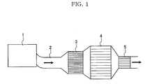
- Fig. 1 shows an outline of an exhaust gas purifying apparatus for a diesel engine according to the present invention.
- An exhaust gas exhausted from a diesel engine 1 is purified by an NOx purification catalyst 3, a diesel particulate filter (hereinafter referred to as a DPF) 4, and an oxidation catalyst 5 in the process of an exhaust gas channel 2, that is, of passing through an exhaust pipe.
- NOx purification catalyst 3 a diesel particulate filter (hereinafter referred to as a DPF) 4
- oxidation catalyst 5 in the process of an exhaust gas channel 2, that is, of passing through an exhaust pipe.
- the present invention allows the NOx purification catalyst 3 to be arranged on the upstream side of a flow of an exhaust gas than the DPF 4 or the oxidation catalyst 5 toward the flow of the exhaust gas, and because a catalyst temperature is easy to rise, and the precise control of temperature and an atmosphere is enabled, sufficient NOx purification performance can be obtained.
- Changing an exhaust gas into a reducing atmosphere is enabled by using a fuel secondary injection that injects the second fuel into an engine cylinder (combustion chamber) in the expansion stroke or the exhaust stroke in addition to a normal fuel injection (main injection) in the diesel engine 1 without providing a special reducing agent addition apparatus.
- the NOx purification catalyst 3 is provided on the upstream side than the DPF 4 toward a flow of an exhaust gas, there is no more than a small fear of the deterioration of the NOx purification catalyst 3 caused by the heat and SOx generated when PM is burned in the DPF 4.
- NOx is purified by the NOx purification catalyst 3 on the upstream side than the DPF 4, and the NOx is not used for the removal of PM, an NOx discharge is suppressed.
- the CO or HC can be oxidized and purified by allowing the oxidation catalyst 5 to be arranged on the downstream side than the DPF 4.
- the timing at which an exhaust gas or the NOx purification catalyst 3 is heated can conform to each of the following methods (1) to (5) so that the temperature at which the NOx purification catalyst 3 functions sufficiently may be reached, when:
- the time when a state in which there are many reducing agents is maintained in comparison with a lean operation or the number of reducing agents that are projected so as to be maintained can be determined considering the characteristics of the NOx purification catalyst 3 or the specifications and characteristics of the diesel engine 1 beforehand, as described previously. These can be realized by adjusting a stroke, an injection time, and injection intervals in fuel injection valve of the diesel engine 1.
- the timing at which an exhaust gas or the DPF 4 is heated can conform to each of the following methods so that temperature at which the PM starts burning may be reached, when:
- a honeycomb-shaped monolith type catalyst which is constructed by adding an alkali metal such as K or Na, an alkali earth metal, such as Ca or Ba, a transition metal, such as Ti, Mn, Fe, or Cu, a rare earth metal such as Zr or Ce, or the Zr or these optional combinations to a fire resistant inorganic material of a high ratio surface area such as alumina, in which a precious metal is carried.
- Fig. 2 shows the diesel engine 1 and its intake and exhaust system, and an engine control unit (ECU) 14.
- the exhaust gas purifying apparatus of the present invention is provided in the exhaust system.
- the exhaust gas purifying apparatus of this embodiment arranges an NOx adsorption and reduction type catalyst 6, the diesel particulate filter (DPF) 4 that oxidizes and removes particulate matters in an exhaust gas, and the oxidation catalyst 5 from the upstream side, viewed from a flow of an exhaust gas that flows in the exhaust gas channel 2 of the diesel engine 1.
- DPF diesel particulate filter
- An oxygen concentration sensor (or A/F sensor) 9 and an exhaust temperature sensor 10 are provided on the upstream side of an NOx adsorption and reduction type catalyst 6.
- a pressure sensor 11 and an exhaust temperature sensor 12 are provided on the downstream side of the NOx adsorption and reduction type catalyst 6, and on the upstream side of the DPF 4. Furthermore, a further pressure sensor 13 is provided on the downstream side of the DPF 4.
- An air flow sensor 7 that measures an intake air volume, and a throttle valve 8 that measures and controls the intake air volume are provided in the intake system of the diesel engine 1.
- the DPF 4 has a PM capture function.
- a ceramic caking body, a ceramic fiber, and a metal can be used. Filters of various forms or sizes can be selected properly in accordance with the space to be used, such as a filter around which the ceramic filter is wound in a coil form and which is molded in a cylindrical type, a filter in which the woven fiber is molded in a proper shape, and a wall flow type filter made of ceramics in which an exhaust gas route whose upstream side end is closed and whose downstream side end is opened, and an exhaust gas route whose upstream side end is opened and whose lower steam end is closed are arranged alternately, and in which a porous wall surface is formed between the adjacent exhaust gas routes.
- the wall flow type filter applies to this embodiment.
- the oxidation catalyst 5 has a function of adsorbing and oxidizing CO, HC, NOx, and SOF and accelerating the combustion of PM.
- Various catalysts including precious metals (Pt and Pd), for example, Pt/zirconia and Pd/alumina as well as Pt/alumina in which the Pt is carried in the alumina can be illustrated as these catalysts.
- a three-way catalyst having a nitrogen oxides reduction function may also be used as the oxidation catalyst 5.
- Catalysts in which precious metals (Pt, Pd, and Rh) are carried in a carrier, such as alumina, for example, the Pt/alumina, the Pd/alumina, or the Rh/alumina are enumerated as these catalysts.
- a hydrocarbon adsorption and combustion catalyst 16 can also be used as an oxidation catalyst, as shown in Fig. 3.
- a hydrocarbon adsorption and combustion catalyst 16 is an oxidation catalyst that adsorbs hydrocarbon in an exhaust gas when a catalyst temperature is low and the activity of the oxidation catalyst is low, and can burn the adsorbed hydrocarbon using the oxidation catalyst when the catalyst temperature rises and the activity of the oxidation catalyst increases.
- Catalysts consisting of an alkali metal such as Cs, having an acid carried in zeolite using the zeolite as a carrier, an alkali earth metal, such as Ca, a first metal oxide composed of a transition metal such as Cu or Ag, a rare earth metal such as Ce or La having oxygen occlusion and emission capability, or a second metal oxide such as Zr, and a precious metal carried in a porous carrier are enumerated as these catalysts.
- the NOx adsorption and reduction type catalyst 6 arranged on the upstream side of the DPF 4 chemically adsorbs NOx in an NOx scavenger.
- the catalyst 6 includes at least one type of an element chosen from potassium, sodium, magnesium, strontium, and calcium, at least one type of an element chosen from a rare earth metal such as cerium, at least one type of an element chosen from a precious metal such as platinum, rhodium, or palladium, and at least one type of an element chosen from titanium or silicon, and is a composite composed of a metal, metal oxides, or a compound oxide, or a composite in which the composite is carried in porous heat resistant metal oxides.
- the NOx adsorption and reduction type catalyst 6, as disclosed in JP-A No. 118458/1998 of the Japanese Laid-Open Patent Publication, is composed of an alkali metal and titanium, and, as disclosed in JP-A No. 10932/1998 of the Japanese Laid-Open Patent Publication, is composed of a composite of the alkali metal and the titanium.
- the mechanism of NOx capture caused by the adsorption the NOx adsorption and reduction type catalyst 6 performs chemically adsorbs the NO 2 generated on a precious metal (refer to the Formula (1)) on the surface of an NOx absorbent with the NO 2 left behind as is (refer to a formula (3)).
- the captured NOx that is, the NO 2 chemically adsorbed on the surface of an NOx absorbent is reduced and purified to N 2 using a reducing agent the HC, CO, and H 2 in an exhaust gas produce when the exhaust gas is in a stoichiometric-rich atmosphere (hereinafter referred to as an excess fuel atmosphere or a non-oxygen atmosphere as a general) (refer to a formula (4)).
- the chemical adsorption in which NO 2 is adsorbed on the surface of an NOx absorbent is fast in the rate of reduction of the captured NO 2 , and the time when a stoichiometric-rich atmosphere is retained can be shortened to several seconds to several minutes. This allows fuel economy to be improved.
- High NOx purification performance is obtained in a diesel engine by selectively obtaining a stoichiometric-rich atmosphere using this exhaust gas purifying apparatus. Because the diesel engine basically performs a lean operation, the diesel engine must be controlled so that the air-fuel ratio of an exhaust gas that flows into the NOx adsorption and reduction type catalyst 6 may be made stoichiometric-rich. This control includes a fuel secondary injection and a decrease in oxygen concentration by an intake venturi.
- the ECU 14 uses a microcomputer system, and is provided with an I/O-LSI as an input/output interface, an MPU (micro processing unit), a RAM and a ROM that store many control programs, and a timer counter.
- I/O-LSI input/output interface
- MPU micro processing unit
- RAM random access memory
- ROM read-only memory
- timer counter timer counter
- the exhaust gas exhausted from the diesel engine 1 first, flows into the NOx adsorption and reduction type catalyst 6. After the NOx adsorption and reduction type catalyst oxidizes NO in the exhaust gas to NO 2 during a normal lean operation, the catalyst chemically adsorbs this NO 2 . Before the adsorbed NO 2 reaches the amount of NO 2 equilibrium adsorption of the NOx adsorption and reduction type catalyst 6, the exhaust gas is made into a reducing atmosphere (stoichiometric-rich), and reduces and purifies the absorbed NO 2 to nitrogen (N 2 ).
- the means of changing the exhaust gas into the reducing atmosphere there are a means of increasing hydrocarbon concentration (a fuel secondary injection of an engine), and a means of reducing oxygen concentration (an intake venturi), and both the means can be used at the same time.
- the catalyst temperature of the NOx adsorption and reduction type catalyst 6 is controlled from 250 to 500 °C. This is because the NOx purification capability of the NOx adsorption and reduction type catalyst 6 is excellent at the temperatures within the foregoing range.
- the DPF 4 is a honeycomb type filter made of ceramics. Inside the DPF 4, this filter is a wall flow type filter in which an exhaust gas route whose upstream side end is closed and whose downstream side end is opened, and an exhaust gas route whose upstream side end is opened and whose lower end is closed are arranged alternately, and in which a porous wall surface is formed between the adjacent exhaust gas routes.
- the exhaust that flows into the DPF 4 flows into an exhaust gas channel whose upstream side end is opened and whose downstream side end is closed, and subsequently, from a porous wall surface provided between the adjacent exhaust gas channels, flows into an exhaust gas channel whose upstream side end is closed and whose downstream side is opened, and flows out to the downstream side.
- the PM in a diesel exhaust gas is collected by a collision onto the wall surface or adsorption.
- the PM collected by the DPF 4 is burned and removed (ashed and removed) by allowing an exhaust gas temperature to increase when a fixed amount of the PM is accumulated.
- the method for increasing the exhaust gas temperature may be either by engine control or by the heat of reaction of the catalyst arranged on the upstream side of the DPF 4.
- a part of the PM burned in the DPF 4 changes into CO by incomplete combustion, and there is a fear of even unburned HC being exhausted.
- the oxidation catalyst 5 is arranged on the downstream side of the exhaust gas channel of the DPF 4, and the oxidation catalyst 5 oxidizes and purifies the CO and unburned HC that were generated by the incomplete combustion of the PM. Moreover, the oxidation catalyst 5 is not consumed by the NOx adsorption and reduction type catalyst 6 or the DPF 4 except for the PM combustion, but oxidizes and purifies the HC or CO included in an exhaust gas.
- this oxidation catalyst 5 is obtained in the same manner even in the case of the hydrocarbon adsorption and combustion catalyst 16 shown in Fig. 3. Besides, in the case of the hydrocarbon adsorption and combustion catalyst 16, even if the catalyst temperature of an HC adsorption and combustion catalyst is low, and the HC included in the exhaust gas cannot be burned and purified such as immediately after an engine starts, the discharge of the HC can be reduced by adsorbing and retaining the HC until the temperature at which the catalyst can sufficiently burn and purify the HC is reached.
- the embodiment shown in Fig. 4 further adds a heater 17 that heats an exhaust gas that flows into the NOx adsorption and reduction type catalyst 6 and a heater 18 that heats the DPF 4.
- a heater 17 that heats an exhaust gas that flows into the NOx adsorption and reduction type catalyst 6
- a heater 18 that heats the DPF 4.
- Another configuration is the same as the embodiment shown in Fig. 2.
- an exhaust gas exhausted from the diesel engine 1 is heated by the heater 17, and the HC in the exhaust gas is dissolved.
- the hydrocarbon in the exhaust gas exhausted from the diesel engine 1 is often higher hydrocarbon whose number of carbons is 7 or more. Accordingly, the NOx reduced reaction in the NOx adsorption and reduction type catalyst 6 on the downstream side of an exhaust gas channel can be advanced by dissolving the hydrocarbon by the heater 17 and increasing a ratio of lower hydrocarbon whose number of carbons is less than 6.
- the heater 17 heats an exhaust gas according to an instruction of the ECU 4 when an exhaust temperature rise is judged to be necessary by the ECU 14 in the NOx purification in the NOx adsorption and reduction type catalyst 6 and the combustion and removal of the PM in the DPF 4.
- the heater 18 heats the DPF 4 according to an instruction of the ECU 14 when the rise of the DPF temperature is judged to be necessary by the ECU 14 in the combustion and removal of the PM in the DPF 4.
- the exhaust gas purification performance can be improved further by providing the heaters 17 and 18.
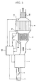
- Fig. 5 shows one embodiment of a direct injection diesel engine to which the exhaust gas purifying apparatus according to the present invention is applied.
- a fuel system of the diesel engine 1 adopts an electronically controlled common rail system.
- the fuel (diesel oil) of a fuel tank 21 is pressurized by a primary pump 22, and furthermore pressurized into the high pressure necessary for a direct injection by a high pressure pump 23.
- High pressure fuel is supplied to a common rail 24 that is an accumulated pressure volume portion.
- Fuel injection nozzle (injector) 26 for direct injection for every combustion chamber 25 of the diesel engine 1 is connected to the common rail 24.
- the fuel injection nozzle 26 directly injects high pressure fuel to the combustion chamber 24.
- the amount of fuel injection and the fuel injection timing by the fuel injection nozzle 25 are controlled by the ECU 14.
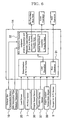
- the ECU 14 has an air-fuel ratio control unit (fuel supply-intake air volume control unit) 31 that controls the amount of fuel injection or the fuel injection time by the fuel injection nozzle 25 and the intake air volume by the motor-driven throttle valve 8, an amount of NOx estimation unit 32, an exhaust gas temperature judgment unit 33, and an amount of particulate capture estimation unit 34. These are embodied by allowing an MPU of the ECU 14 to execute a control program.
- air-fuel ratio control unit fuel supply-intake air volume control unit
- the amount of NOx estimation unit 32 estimates the amount of NOx stored in the NOx adsorption and reduction type catalyst 6 from a measured value of a physical quantity that stands for an operation condition of the diesel engine 1 such as temperature, an air-fuel ratio, oxygen concentration, a lean operation time, of an exhaust gas that flows into the NOx adsorption and reduction type catalyst 6.
- the air-fuel ratio control unit 31 When the amount of accumulated NOx estimated by the NOx amount estimation means 32 reaches a fixed value, the air-fuel ratio control unit 31 performs the control of increasing the temperature of the exhaust gas that flows into the NOx adsorption and reduction type catalyst 6 to the temperature necessary for the NOx reduction and purification, and supplying fuel that is a reducing agent necessary for reducing the accumulated NOx to the exhaust gas.
- Supplying fuel that is a reducing agent necessary for reducing NOx to an external gas can be realized by increasing the amount of fuel supplied to the diesel engine 1 by the electronically controlled injector 26 controlling an intake air volume, and performing the fuel secondary injection in which the fuel is injected to the engine combustion chamber 25 by the electronically controlled injector 26 in the expansion stroke or the exhaust stroke of the diesel engine 1.
- the exhaust gas temperature judgment unit 33 judges the exhaust gas temperature measured by the exhaust temperature sensor 12 that measures the exhaust temperature that flows into the DPF 4 is lower than a predetermined temperature.
- the amount of particulate capture estimation unit 34 estimates the amount of particulate captured by the DPF 4.
- the control of heating the exhaust gas into the predetermined temperature is performed by the heaters 17 and 18, and the particulate captured by the DPF 4 is burned and removed.
- Fuel concentration (hereinafter referred to as an air-fuel ratio) of an air-fuel mixture supplied to the diesel engine 1 is controlled as follows.
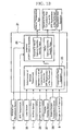
- Fig. 6 is a block diagram of the air-fuel ratio control.
- the air-fuel ratio control unit 31 of the ECU 14 determines an air-fuel ratio (A/F) from information about an output signal of a load sensor 35 that outputs a signal in accordance with the full pedal depression of an accelerator pedal, an output signal of the amount of intake measured by the air flow sensor 7, an engine speed signal detected by a crank angle sensor (engine speed sensor 36), an exhaust gas temperature signal outputted by the exhaust gas temperature sensor 10, an output signal of a throttle sensor 37 that detects a throttle opening, an engine coolant temperature signal outputted by an engine coolant temperature sensor 38, and a starter signal.
- A/F air-fuel ratio
- the air-fuel control unit 31 corrects this air-fuel ratio based on a signal fed back from the oxygen sensor 9, and determines the amount of fuel injection. Further, the control unit stops feedback control using a signal of each sensor and switch at low temperature, in an idling state, and in a high load. Moreover, an air-fuel ratio correction leaning function is used so that the air-fuel ratio correction learning function can cope with a fine change or a sudden change of an air-fuel ratio.
- the injection condition of the injector 26 is determined according to the instruction of the ECU 14, and a rich operation is performed.
- the existence of the NOx adsorption capability of the NOx adsorption and reduction type catalyst 6 is judged by the amount of NOx estimation unit 32.
- the adsorption capability exceeds the fixed specific value (for example, 50% of the amount of equilibrium adsorption)
- the amount of fuel injection is determined so as to perform the lean operation as specified.
- the adsorption capability is judged to be less than the fixed specific value, an air-fuel ratio is shifted to the rich side over a fixed period of time and the NOx adsorption and reduction type catalyst 6 is regenerated.
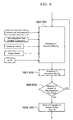
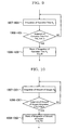
- Fig. 7 is a flowchart of air-fuel ratio control.
- a step 1002 signals that instruct various operation conditions, or detect operation conditions are read.
- a step 1003 an air-fuel ratio is determined based on these signals.
- the determined air-fuel ratio is detected.
- a step 1005 the size between the determined air-fuel ratio and a theoretical air-fuel ratio is compared.
- the theoretical air-fuel ratio to be compared here is an air-fuel ratio in which the rate of the NOx contact reduced reaction excels a capture rate caused by adsorption in the NOx adsorption and reduction type catalyst 6, to be accurate, and is determined by previously estimating the characteristics of the NOx adsorption and reduction type catalyst 6, and the air-fuel ratio in the vicinity of the theoretical air-fuel ratio is selected.
- processing advances to a step 1006, and an air-fuel ratio operation is performed as specified without performing the regeneration operation of an NOx adsorption and reduction type catalyst.
- step 1007 an estimation operation of the amount of NOx adsorption is performed.
- the estimation operation method of the amount of NOx adsorption is described later.
- a step 1008 whether the estimated amount of NOx adsorption is less than a fixed limit (there is adsorption capability) or not is judged.
- the amount of critical adsorption is set to a value in which the NOx in an exhaust gas can sufficiently be purified by estimating NOx capture characteristics of the NOx adsorption and reduction type catalyst 6 by way of experimenting previously and considering the exhaust gas temperature or the NOx adsorption and reduction type catalyst temperature.
- processing advances to the step 1006, and air-fuel ratio operation is performed as specified without performing the regeneration operation of an NOx adsorption and reduction type catalyst.
- processing advances to a step 1009, and an air-fuel ratio is shifted to the rich side.
- a rich shift time Tr is counted and integrated, and, in a step 1011, whether an elapsed time Tr exceeds a fixed time (Tr) c or not is judged. a rich shift is performed only for the fixed time (Tr) c.
- a step 1012 an integrated value of the rich shift time Tr is reset (cleared), and the rich shift is terminated.
- Fig. 8 is a flowchart of the processing that integrates and judges an NOx discharge from various operation conditions during a lean operation.
- a signal regarding the action of the NOx adsorption and reduction type catalyst 6 such as an exhaust gas temperature, and a signal regarding various engine operation conditions that affect the NOx concentration in the exhaust gas are read, and an amount of NOx E N adsorbed in a unit hour is estimated.
- a step 1007-E02 the E N is integrated, and, in a step 1008-E01, the size between an integrated value ⁇ E N and the upper limit value (E N )c of the amount of adsorption is compared. If the condition of ⁇ E N ⁇ (E N ) c is satisfied, integration is continued. If the condition of ⁇ E N > (E N )c is satisfied, in a step of 1008-E02, the integration is reset and processing advances to the step 1009.
- Fig. 9 is a flowchart of the processing that judges an operation time from the integration time of a lean operation.
- a lean operation time H L is integrated, and, in a step 1008-H01, the size between an integrated value ⁇ H L and the upper limit value (H L )c of the integration time is compared. If the condition of ⁇ H L ⁇ (H L )c is satisfied, the integration is continued. If the condition of ⁇ H L > (H L )c is satisfied, in a step 1008-H02, the integration is rest, and processing advances to the step 1009.
- Fig. 10 is a flowchart of the processing that judges an amount of oxygen using an oxygen sensor signal during a lean operation.
- a step 1007-001 an amount of oxygen Q 0 during the lean operation is integrated, and, in a step 1008-001, the size between an integrated value ⁇ Q 0 and the upper limit value (Q 0 )c of an integrated oxygen value is compared. If the condition of ⁇ Q 0 ⁇ (Q 0 )c is satisfied, integration is continued. If the condition of ⁇ Q 0 > (Q 0 )c is satisfied, in a step 1008-002, the integration is reset, and processing advances to the step 1009.
- Fig. 11 is a flowchart of the processing that judges an NOx discharge using an NOx concentration sensor signal detected at the entrance of the NOx adsorption and reduction type catalyst during a lean operation.
- a step 1007-N01 an amount of NOx Q N at the entrance of the NOx adsorption and reduction type catalyst is integrated based on an NOx concentration sensor signal.
- a step 1008-N01 an integrated value ⁇ Q N and the upper limit value (Q N )c of the amount of integrated NOx is compared. If the condition of ⁇ Q N ⁇ (Q N )c is satisfied, integration is continued. If the condition of ⁇ Q N > (Q N )c is satisfied, in a step 1008-N02, the integration is reset, and processing advances to the step 1009.
- Fig. 12 is a flowchart of the processing that judges NOx concentration using an NOx concentration sensor signal detected at the entrance of the NOx adsorption and reduction type catalyst during a lean operation.
- a step 1007-C01 an NOx concentration C N at the entrance of an NOx adsorption and reduction type catalyst is detected based on an NOx concentration sensor signal.
- a step 1008-C01 the size between C N and the upper limit (C N )c of the C N is compared. If the condition of C N ⁇ (C N )c is satisfied, detection is continued. If the condition of C N > (C N )c is satisfied, processing advances to the step 1009.
- FIG. 13 is a block diagram of the exhaust temperature control.
- the exhaust gas temperature judgment unit 33 of the ECU 14 determines an exhaust temperature from information about an output signal of a load sensor 35 that outputs a signal in accordance with the full pedal depression of an accelerator pedal, an output signal of the amount of intake measured by the air flow sensor 7, an engine speed signal detected by a crank angle sensor (engine speed sensor 36), an exhaust gas temperature signal the exhaust gas temperature sensor 12 outputs, an output signal of a throttle sensor 37 that detects a throttle opening, an engine coolant temperature signal an engine coolant temperature sensor 38 outputs, and a starter signal.
- This exhaust temperature is further corrected based on a signal fed back from the oxygen sensor 2, and determines the amount of heat supplied from the diesel engine 1. Further, at low temperature, in idling operation, and in a high load, feedback control is stopped using a signal of each sensor and switch. Moreover, an air-fuel ratio correction leaning function is used so that the air-fuel ratio correction learning function can cope with even a fine change or a sudden change of an air-fuel ratio.
- the determined exhaust temperature is PM combustion start temperature
- the amount of heat supply condition by the engine 1 is determined according to an instruction of the ECU 31, and the heating of exhaust is performed.
- Fig. 14 is a flowchart of temperature control (DPF regeneration control).
- an exhaust temperature is detected.
- the size between the exhaust temperature and PM combustion start temperature is compared.
- the PM combustion start temperature to be compared here is the temperature at which the speed of PM combustion and purification exceeds a capture speed in the DPF 4, and is determined by previously estimating the characteristics of the DPF 4.
- processing advances to a step 2006, an operation is performed as specified without performing the regeneration operation of the DPF 4.
- step 2007 the estimation operation of the amount of PM capture is performed. An estimation operation method is described later.
- a step 2008 whether the estimated amount of PM capture is below a fixed critical amount or not is judged.
- the amount of critical capture previously estimates PM capture characteristics of a DPF by means of experiment, and the PM in an exhaust gas is set in a value that can be purified sufficiently.
- processing advances to the step 2006, and an operation is performed as specified without performing the regeneration operation of the DPF.
- processing advances to a step 2009. The amount of supplied heat of the diesel engine 1 is determined, and an exhaust temperature is raised.
- an exhaust temperature rise time Th is counted and integrated, and, in a step 2011, whether an elapsed time Th exceeds a fixed time (Th)c or not is judged.
- An exhaust temperature rise is performed only for the fixed time (Th)c.
- an integrated value of the exhaust temperature rise time Th is reset (cleared), and the exhaust temperature rise is terminated.
- the amount of DPF capture estimation processing by the amount of DPF capture estimation unit 34 is described with reference to Figs. 15 to 17.
- Fig. 15 is a flowchart of the processing that integrates and judges the amount of DPF collection from various operation conditions during a lean operation.
- a signal regarding the actuation condition of a DPF such as an exhaust gas temperature, and a signal regarding various engine operation conditions that affect the PM concentration in the exhaust gas are read, and an amount of PM D N that is adsorbed in a unit hour is estimated.
- the D N is integrated, and, in a step 2008-D01, the size between an integrated value ⁇ D N and the upper limit value (D N )c of the amount of collection is compared. If the condition of ⁇ D N ⁇ (D N )c is satisfied, integration is continued. If the condition of ⁇ D N > (D N )c is satisfied, in a step of 2008-D02, the integration is reset and processing advances to the step 2009.
- Fig. 16 is a flowchart of the processing that judges an operation time from an integration time of the operation in which the temperature rise control for DPF regeneration is not performed.
- a step 2007-101 an operation time I L at which the temperature rise control for the DPF regeneration is not performed is integrated, and the size between an integrated value ⁇ I L and the upper limit value (I L )c of an integration time is compared. If the condition of ⁇ I L ⁇ (I L )c is satisfied, integration is continued. If the condition of ⁇ I L > (I L )c is satisfied, in a step 2008-102, the integration is reset, and processing advances to the step 2009.
- Fig. 17 is a flowchart of the processing that judges the amount of pressure difference integration using a pressure sensor signal during an operation in which the temperature rise control for DPF regeneration is not performed.
- a pressure difference ⁇ P 0 before and behind a DPF is integrated, and, in a step 2008-P01, an integrated value ⁇ P 0 and a specific value P 0 (c) is compared.
- the ⁇ P 0 is less than the specific value P 0 (c)
- integration is continued.
- the ⁇ P 0 exceeds the specific value P 0 (c)
- the integration is reset, and processing advances to the step 2009.
- An exhaust gas purifying apparatus can apply to a diesel engine for vehicles such as automobiles, and can reduce and purify nitrogen oxides in an exhaust gas using an NOx adsorption and reduction type catalyst, and then can capture particulate matters in the exhaust gas by a diesel particulate filter, and can burn and purify an accumulated PM. At this time, carbon monoxide in which the particulate matters burn incompletely and which was produced can be oxidized and purified using either an oxidation catalyst or an HC adsorption and combustion catalyst, and air pollution can be prevented.
Landscapes
- Engineering & Computer Science (AREA)
- Chemical & Material Sciences (AREA)
- Combustion & Propulsion (AREA)
- Mechanical Engineering (AREA)
- General Engineering & Computer Science (AREA)
- Health & Medical Sciences (AREA)
- Materials Engineering (AREA)
- Chemical Kinetics & Catalysis (AREA)
- Toxicology (AREA)
- Exhaust Gas After Treatment (AREA)
- Processes For Solid Components From Exhaust (AREA)
- Electrical Control Of Air Or Fuel Supplied To Internal-Combustion Engine (AREA)
- Exhaust Gas Treatment By Means Of Catalyst (AREA)
Applications Claiming Priority (3)
| Application Number | Priority Date | Filing Date | Title |
|---|---|---|---|
| JP2002244502 | 2002-08-26 | ||
| JP2002244502 | 2002-08-26 | ||
| PCT/JP2003/010751 WO2004018850A1 (ja) | 2002-08-26 | 2003-08-26 | ディーゼルエンジンの排気ガス浄化装置および排気ガス浄化方法 |
Publications (1)
| Publication Number | Publication Date |
|---|---|
| EP1544428A1 true EP1544428A1 (en) | 2005-06-22 |
Family
ID=31944169
Family Applications (1)
| Application Number | Title | Priority Date | Filing Date |
|---|---|---|---|
| EP03792839A Withdrawn EP1544428A1 (en) | 2002-08-26 | 2003-08-26 | Apparatus and method for clarifying exhaust gas of diesel engine |
Country Status (4)
| Country | Link |
|---|---|
| US (1) | US20060107649A1 (ja) |
| EP (1) | EP1544428A1 (ja) |
| JP (2) | JPWO2004018850A1 (ja) |
| WO (1) | WO2004018850A1 (ja) |
Cited By (7)
| Publication number | Priority date | Publication date | Assignee | Title |
|---|---|---|---|---|
| EP1728984A3 (de) * | 2005-05-30 | 2006-12-20 | J. Eberspächer GmbH & Co. KG | Abgasanlage |
| WO2008149234A2 (en) * | 2007-06-05 | 2008-12-11 | Delphi Technologies, Inc. | Internal combustion engine system |
| WO2009016822A3 (en) * | 2007-08-01 | 2009-03-19 | Nissan Motor | Exhaust gas purifying system |
| FR2928413A1 (fr) * | 2008-03-10 | 2009-09-11 | Renault Sas | Procede de gestion du fonctionnement d'au moins un convertisseur catalytique pour moteur a combustion interne |
| WO2009136029A1 (fr) * | 2008-05-07 | 2009-11-12 | Renault S.A.S | Procede de regeneration d'un systeme de post traitement par fractionnement de la richesse |
| EP2253823A3 (en) * | 2009-05-18 | 2011-11-02 | Mitsubishi Jidosha Kogyo Kabushiki Kaisha | Exhaust emission control device |
| US8437943B2 (en) | 2010-01-28 | 2013-05-07 | Deere & Company | NOx control during load increases |
Families Citing this family (23)
| Publication number | Priority date | Publication date | Assignee | Title |
|---|---|---|---|---|
| US20080256936A1 (en) * | 2007-04-17 | 2008-10-23 | Geo2 Technologies, Inc. | Selective Catalytic Reduction Filter and Method of Using Same |
| JP4103720B2 (ja) * | 2003-07-31 | 2008-06-18 | 日産自動車株式会社 | エンジンの排気浄化装置および微粒子捕集フィルタにおける微粒子堆積量状態判定方法 |
| JP4248427B2 (ja) * | 2004-03-11 | 2009-04-02 | トヨタ自動車株式会社 | 内燃機関排気浄化装置の粒子状物質再生制御装置 |
| US20080241032A1 (en) * | 2007-04-02 | 2008-10-02 | Geo2 Technologies, Inc. | Catalyzing Lean NOx Filter and Method of Using Same |
| US20080236145A1 (en) * | 2007-04-02 | 2008-10-02 | Geo2 Technologies, Inc. | Emission Control System using a Multi-Function Catalyzing Filter |
| JP2006242072A (ja) * | 2005-03-02 | 2006-09-14 | Mitsubishi Fuso Truck & Bus Corp | 内燃機関の排気浄化装置 |
| JP2007077855A (ja) * | 2005-09-13 | 2007-03-29 | Hino Motors Ltd | 排気浄化装置 |
| US7211232B1 (en) * | 2005-11-07 | 2007-05-01 | Geo2 Technologies, Inc. | Refractory exhaust filtering method and apparatus |
| JP4523911B2 (ja) * | 2005-12-14 | 2010-08-11 | 本田技研工業株式会社 | 排ガス浄化装置 |
| EP2153032B1 (en) * | 2007-05-01 | 2016-07-27 | Mack Trucks, Inc. | Method and arrangement for maintaining a diesel particulate filter in a diesel engine exhaust system |
| EP2112341B1 (en) | 2008-04-22 | 2018-07-11 | Umicore AG & Co. KG | Method for purification of an exhaust gas from a diesel engine |
| DE102008038720A1 (de) * | 2008-08-12 | 2010-02-18 | Man Nutzfahrzeuge Ag | Verfahren und Vorrichtung zur Regeneration eines im Abgasstrang einer Brennkraftmaschine angeordneten Partikelfilters |
| EP2386735B1 (en) | 2009-01-09 | 2015-09-16 | Toyota Jidosha Kabushiki Kaisha | Exhaust gas purification apparatus for an internal combustion engine |
| JP5532682B2 (ja) * | 2009-05-28 | 2014-06-25 | いすゞ自動車株式会社 | 排気浄化装置 |
| GB2475097A (en) * | 2009-11-06 | 2011-05-11 | Total Vehicle Technology Ltd | Analysing an exhaust gas using an inorganic filter |
| WO2011102487A1 (ja) * | 2010-02-22 | 2011-08-25 | 日立金属株式会社 | セラミックハニカム構造体及びその製造方法 |
| TWI390104B (zh) * | 2010-03-04 | 2013-03-21 | Nat Univ Tsing Hua | 控制廢氣排放並發電的熱活電化學暨觸媒轉化器 |
| JP5533259B2 (ja) * | 2010-05-25 | 2014-06-25 | いすゞ自動車株式会社 | 排気ガス浄化システム |
| US8444730B2 (en) * | 2010-09-27 | 2013-05-21 | Ford Global Technologies, Llc | Even-loading DPF and regeneration thereof |
| CN102322318B (zh) * | 2011-07-27 | 2014-04-30 | 江铃汽车股份有限公司 | 一种汽车尾气处理装置 |
| DE102013012566A1 (de) | 2013-07-29 | 2015-01-29 | Man Diesel & Turbo Se | Verfahren zum Betreiben einer Brennkraftmaschine |
| CN105056970B (zh) * | 2015-08-17 | 2018-12-11 | 中自环保科技股份有限公司 | 一种柴油车催化剂型颗粒物净化器的制备方法 |
| CN111828187A (zh) * | 2020-07-31 | 2020-10-27 | 江铃汽车股份有限公司 | 一种柴油氮氧化物存储及催化反应控制策略 |
Family Cites Families (12)
| Publication number | Priority date | Publication date | Assignee | Title |
|---|---|---|---|---|
| JP2675405B2 (ja) * | 1989-08-12 | 1997-11-12 | マツダ株式会社 | エンジンの排気ガス浄化装置 |
| JP2549482Y2 (ja) * | 1990-12-14 | 1997-09-30 | 三菱自動車工業株式会社 | 排気ガス処理装置 |
| JP3899534B2 (ja) * | 1995-08-14 | 2007-03-28 | トヨタ自動車株式会社 | ディーゼル機関の排気浄化方法 |
| US6293096B1 (en) * | 1999-06-23 | 2001-09-25 | Southwest Research Institute | Multiple stage aftertreatment system |
| JP2001050033A (ja) * | 1999-08-09 | 2001-02-23 | Hitachi Ltd | 排気浄化制御装置 |
| JP3642017B2 (ja) * | 2000-10-18 | 2005-04-27 | トヨタ自動車株式会社 | 内燃機関の排気浄化装置 |
| JP2003065116A (ja) * | 2001-08-24 | 2003-03-05 | Nissan Motor Co Ltd | 内燃機関の排気浄化装置 |
| US6912847B2 (en) * | 2001-12-21 | 2005-07-05 | Engelhard Corporation | Diesel engine system comprising a soot filter and low temperature NOx trap |
| US6813884B2 (en) * | 2002-01-29 | 2004-11-09 | Ford Global Technologies, Llc | Method of treating diesel exhaust gases |
| US6915629B2 (en) * | 2002-03-07 | 2005-07-12 | General Motors Corporation | After-treatment system and method for reducing emissions in diesel engine exhaust |
| US6820414B2 (en) * | 2002-07-11 | 2004-11-23 | Fleetguard, Inc. | Adsorber aftertreatment system having downstream soot filter |
| US7062904B1 (en) * | 2005-02-16 | 2006-06-20 | Eaton Corporation | Integrated NOx and PM reduction devices for the treatment of emissions from internal combustion engines |
-
2003
- 2003-08-26 EP EP03792839A patent/EP1544428A1/en not_active Withdrawn
- 2003-08-26 US US10/522,774 patent/US20060107649A1/en not_active Abandoned
- 2003-08-26 WO PCT/JP2003/010751 patent/WO2004018850A1/ja active Application Filing
- 2003-08-26 JP JP2004530622A patent/JPWO2004018850A1/ja active Pending
-
2009
- 2009-01-19 JP JP2009009314A patent/JP2009092076A/ja not_active Abandoned
Non-Patent Citations (1)
| Title |
|---|
| See references of WO2004018850A1 * |
Cited By (15)
| Publication number | Priority date | Publication date | Assignee | Title |
|---|---|---|---|---|
| EP1728984A3 (de) * | 2005-05-30 | 2006-12-20 | J. Eberspächer GmbH & Co. KG | Abgasanlage |
| WO2008149234A2 (en) * | 2007-06-05 | 2008-12-11 | Delphi Technologies, Inc. | Internal combustion engine system |
| EP2009265A1 (en) * | 2007-06-05 | 2008-12-31 | Delphi Technologies, Inc. | Internal combustion engine system |
| WO2008149234A3 (en) * | 2007-06-05 | 2009-04-02 | Delphi Tech Inc | Internal combustion engine system |
| CN101784763A (zh) * | 2007-08-01 | 2010-07-21 | 日产自动车株式会社 | 排气净化系统 |
| WO2009016822A3 (en) * | 2007-08-01 | 2009-03-19 | Nissan Motor | Exhaust gas purifying system |
| US9810120B2 (en) | 2007-08-01 | 2017-11-07 | Nissan Motor Co., Ltd. | Exhaust gas purifying system |
| CN101784763B (zh) * | 2007-08-01 | 2013-08-21 | 日产自动车株式会社 | 排气净化系统及排气净化方法 |
| WO2009115759A2 (fr) * | 2008-03-10 | 2009-09-24 | Renault S.A.S | Procede de gestion du fonctionnement d'au moins un convertisseur catalytique pour moteur a combustion interne |
| WO2009115759A3 (fr) * | 2008-03-10 | 2009-12-03 | Renault S.A.S | Procede de gestion du fonctionnement d'au moins un convertisseur catalytique pour moteur a combustion interne |
| FR2928413A1 (fr) * | 2008-03-10 | 2009-09-11 | Renault Sas | Procede de gestion du fonctionnement d'au moins un convertisseur catalytique pour moteur a combustion interne |
| FR2930968A1 (fr) * | 2008-05-07 | 2009-11-13 | Renault Sas | Procede de regeneration d'un systeme de post traitement par fractionnement de la richesse. |
| WO2009136029A1 (fr) * | 2008-05-07 | 2009-11-12 | Renault S.A.S | Procede de regeneration d'un systeme de post traitement par fractionnement de la richesse |
| EP2253823A3 (en) * | 2009-05-18 | 2011-11-02 | Mitsubishi Jidosha Kogyo Kabushiki Kaisha | Exhaust emission control device |
| US8437943B2 (en) | 2010-01-28 | 2013-05-07 | Deere & Company | NOx control during load increases |
Also Published As
| Publication number | Publication date |
|---|---|
| JP2009092076A (ja) | 2009-04-30 |
| WO2004018850A1 (ja) | 2004-03-04 |
| JPWO2004018850A1 (ja) | 2005-12-15 |
| US20060107649A1 (en) | 2006-05-25 |
Similar Documents
| Publication | Publication Date | Title |
|---|---|---|
| EP1544428A1 (en) | Apparatus and method for clarifying exhaust gas of diesel engine | |
| EP2149684B1 (en) | Method of controlling nox purification system and nox purification system | |
| JP4417878B2 (ja) | 排気ガス浄化方法及び排気ガス浄化システム | |
| EP1491735B1 (en) | Exhaust gas decontamination system and method of controlling the same | |
| EP1353048B1 (en) | An exhaust gas purification device for an internal combustion engine | |
| JP4304428B2 (ja) | 内燃機関の排気ガス浄化システム | |
| US20050109022A1 (en) | Exhaust gas purifying method and exhaust gas purifying system | |
| JP2012503735A (ja) | 複数の窒素酸化物吸蔵触媒コンバータを有する排ガス後処理のための触媒コンバータのための調整方法 | |
| JP3201237B2 (ja) | 内燃機関の排気浄化装置 | |
| JP4168781B2 (ja) | NOx浄化システムのNOx触媒再生方法及びNOx浄化システム | |
| JP2007255342A (ja) | NOx浄化システムの制御方法及びNOx浄化システム | |
| JP3885814B2 (ja) | 排気ガス浄化装置の昇温方法及び排気ガス浄化システム | |
| KR101724453B1 (ko) | 배기 가스 정화 장치 및 이를 제어하는 방법 | |
| JP2008298024A (ja) | 排ガス浄化装置 | |
| JPH11343836A (ja) | 内燃機関の排気浄化装置 | |
| JP4165085B2 (ja) | エンジンの排気浄化装置 | |
| JP3876905B2 (ja) | 排気ガス浄化システムの脱硫制御方法及び排気ガス浄化システム | |
| WO2007029339A1 (ja) | 内燃機関の排ガス浄化装置及び排ガス浄化方法 | |
| JP5332664B2 (ja) | エンジンの排気浄化装置 | |
| JP4178797B2 (ja) | 内燃機関の排気浄化装置 | |
| JP4045764B2 (ja) | エンジンの排気浄化装置 | |
| JP4019867B2 (ja) | 内燃機関の排気浄化装置 | |
| JP2006274912A (ja) | エンジンの制御装置 | |
| JP2003083028A (ja) | 内燃機関の排気浄化装置 | |
| JP4333612B2 (ja) | 排ガスの浄化装置および排ガス浄化触媒 |
Legal Events
| Date | Code | Title | Description |
|---|---|---|---|
| PUAI | Public reference made under article 153(3) epc to a published international application that has entered the european phase |
Free format text: ORIGINAL CODE: 0009012 |
|
| 17P | Request for examination filed |
Effective date: 20050317 |
|
| AK | Designated contracting states |
Kind code of ref document: A1 Designated state(s): AT BE BG CH CY CZ DE DK EE ES FI FR GB GR HU IE IT LI LU MC NL PT RO SE SI SK TR |
|
| RBV | Designated contracting states (corrected) |
Designated state(s): DE FR IT |
|
| STAA | Information on the status of an ep patent application or granted ep patent |
Free format text: STATUS: THE APPLICATION HAS BEEN WITHDRAWN |
|
| 18W | Application withdrawn |
Effective date: 20090917 |