EP1543754B1 - Appareil de cuisson - Google Patents
Appareil de cuisson Download PDFInfo
- Publication number
- EP1543754B1 EP1543754B1 EP04255510A EP04255510A EP1543754B1 EP 1543754 B1 EP1543754 B1 EP 1543754B1 EP 04255510 A EP04255510 A EP 04255510A EP 04255510 A EP04255510 A EP 04255510A EP 1543754 B1 EP1543754 B1 EP 1543754B1
- Authority
- EP
- European Patent Office
- Prior art keywords
- water feed
- feed pipe
- heating cooker
- water
- feed tank
- Prior art date
- Legal status (The legal status is an assumption and is not a legal conclusion. Google has not performed a legal analysis and makes no representation as to the accuracy of the status listed.)
- Expired - Lifetime
Links
Images


Classifications
-
- F—MECHANICAL ENGINEERING; LIGHTING; HEATING; WEAPONS; BLASTING
- F24—HEATING; RANGES; VENTILATING
- F24C—DOMESTIC STOVES OR RANGES ; DETAILS OF DOMESTIC STOVES OR RANGES, OF GENERAL APPLICATION
- F24C13/00—Stoves or ranges with additional provisions for heating water
-
- F—MECHANICAL ENGINEERING; LIGHTING; HEATING; WEAPONS; BLASTING
- F24—HEATING; RANGES; VENTILATING
- F24C—DOMESTIC STOVES OR RANGES ; DETAILS OF DOMESTIC STOVES OR RANGES, OF GENERAL APPLICATION
- F24C15/00—Details
- F24C15/32—Arrangements of ducts for hot gases, e.g. in or around baking ovens
- F24C15/322—Arrangements of ducts for hot gases, e.g. in or around baking ovens with forced circulation
- F24C15/327—Arrangements of ducts for hot gases, e.g. in or around baking ovens with forced circulation with air moisturising
Definitions
- the present invention relates, in general, to heating cookers and, more particularly, to a heating cooker having a water supplying structure in which a water feed tank is removably inserted into a front part of the heating cooker to supply water to a steam generator.
- heating cookers are cooking apparatuses which heat and cook food placed in a cooking cavity thereof.
- Exemplary conventional heating cookers include microwave ovens, electric ovens, gas ovens, etc.
- conventional heating cookers are disadvantageous in that food is cooked in a dry state while being heated in the cooking cavity, due to evaporation of water contained in the food.
- a heating cooker having a steam generator to supply moisture into food, which is placed in the cooking cavity, by discharging steam into the cooking cavity has been proposed.
- the steam generator of the conventional heating cooker includes a heater which is provided at a predetermined portion outside the cooking cavity to generate the steam, a water feed tank to supply water to the heater, and a water feed pipe to supply the water from the water feed tank to the heater, as proposed in Japan Patent Laid-open Publication No. Heisei. 08-178298 and No. sho. 56-162328 .
- the water feed tank is coupled to the water feed pipe and an inlet, provided on an end of the water feed pipe, is opened. Therefore, when the end of the water feed pipe is moved in a predetermined direction, for example, when the end of the water feed pipe is horizontally moved in the heating cooker, water may undesirably leak from the inlet of the water feed pipe.
- the water feed pipe is installed in the conventional heating cooker so that the inlet of the water feed pipe is placed upward, thus the water feed tank must be removably vertically coupled to the inlet of the water feed pipe. Therefore, where the conventional heating cooker is placed on a shelf or a table, a user must pick up and put down the heavy water feed tank onto the heating cooker to couple the water feed tank to the water feed pipe.
- EP 277,377 discloses a steam oven having a water tank connected to a steam generator with a flexible hose.
- the present invention provides a heating cooker which prevents leakage of water even when an inlet of a water feed pipe is placed in any direction in the heating cooker, and in which a water feed tank is removably coupled to the water feed pipe in any direction.
- a heating cooker including a steam generator to supply steam into a cooking cavity defined in the heating cooker, a water feed tank to supply water into the steam generator, a water feed pipe to supply the water from the water feed tank into the steam generator, with the water feed tank removably coupled to the water feed pipe, a first valve to control an outlet provided on the water feed tank to discharge the water from the water feed tank, and a second valve to control an inlet provided on the water feed pipe to draw the water discharged from the water feed tank into the water feed pipe, wherein the first valve includes a first valve body operable to control the outlet of the water feed tank by a reciprocating motion of the first valve body, and a first elastic unit to support the first valve body and the second valve includes a second valve body operable to control the inlet of the water feed pipe by a reciprocating motion of the second valve body, and a second elastic unit to support the second valve body characterised in that the first elastic unit has an elastic modulus higher than the second elastic unit.
- the first and second valves may be operable to be respectively opened while the water feed tank is coupled to the water feed pipe, and the first and second valves are operable to be respectively closed while the water feed tank is removed from the water feed pipe.
- the first and second valves may be operable to control each other to open or close the second and first valves.
- the first and second valve bodies may correspond to each other at outside ends of the first and second valve bodies.
- the first elastic unit may support the first valve body toward an outside of the water feed tank, and the second elastic unit may support the second valve body toward an outside of the water feed pipe.
- Each of the first and second elastic units may be a compression spring.
- the first valve body may include a first inside part provided at an inside of the outlet of the water feed tank, a first outside part provided at an outside of the outlet of the water feed tank, and a first intermediate part to connect the first inside part to the first outside part.
- the second valve body may include a second inside part provided at an inside of the inlet of the water feed pipe, a second outside part provided at an outside of the inlet of the water feed pipe, and a second intermediate part to connect the second inside part to the second outside part.
- the heating cooker may further include a first packing provided on the first inside part of the first valve body operable to seal the outlet of the water feed tank, and a second packing provided on the second inside part of the second valve body operable to seal the inlet of the water feed pipe.
- the heating cooker may further include a water path defined between the outlet of the water feed tank and the inlet of the water feed pipe to guide the water from the outlet to the inlet.
- the water path may be defined by an insert part extending from the water feed pipe.
- the heating cooker may further include a third packing provided on the insert part of the water feed pipe operable to seal the water path defined by the insert part.
- the water feed tank may further include a receiver to receive the insert part of the water feed pipe.
- the receiver of the water feed tank may be bent at an end thereof toward an axis of the receiver.
- the outlet of the water feed tank and the inlet of the water feed pipe may be provided to face each other in a horizontal direction, and the water feed tank may move to or away from the water feed pipe in the horizontal direction to be coupled to or removed from the water feed pipe.
- the water feed tank may be provided at a predetermined portion in a front part of the heating cooker.
- FIG. 1 is a front perspective view of a heating cooker 100, according to an embodiment of the present invention.
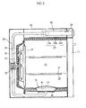
- FIG. 2 is a side sectional view of the heating cooker 100 of FIG. 1.
- the heating cooker 100 includes a casing 10, a cooking cavity 20, which is defined in the casing 10, a first heater 30 to heat food which is placed in the cooking cavity 20, a fan 31 to circulate air within the cooking cavity 20, and a fan motor 32 to drive the fan 31.
- the heating cooker 100 further includes a steam generator 40 to supply steam into the cooking cavity 20, a water feed tank 50 to supply water into the steam generator 40, and a water feed pipe 60 to supply the water from the water feed tank 50 into the steam generator 40.
- the heating cooker 100 further includes a door 11, which is attached to an open front of the casing 10, to rotate around a lower end of the door 11 so that the door 11 may be opened downward and closed upward at the open front of the casing 10.
- the heating cooker 100 further includes a controller 12 which is provided on a predetermined portion of a front surface of the casing 10 above the door 11 to allow a user to manipulate the heating cooker 100.
- the controller 12 includes a display 12a to display an operational state of the heating cooker 100 thereon, various control buttons 12b, and control switches 12c.
- the water feed tank 50 is inserted into a front of the casing 10 at a predetermined portion above the door 11 and opposite to the controller 12.
- the cooking cavity 20 is opened at a front thereof to allow the user to place foods into and remove foods from the cooking cavity 20.
- the heating cooker 100 further includes a plurality of guide rails 22 which are oppositely provided on inner surfaces of both sidewalls of the cooking cavity 20 to correspond to each other.
- the guide rails 22 support opposite edges of upper and lower racks 21, on which foods are placed, and slide along the guide rails 22.
- the casing 10 includes a cavity wall 23, which is provided in the casing 10 to be separated from the casing 10, to define the cooking cavity 20 therein.
- the cavity wall 23 includes an inner wall 23a and an outer wall 23b in a double-layered structure.
- the cavity wall 23 further includes an insulating material 23c which fills a space between the inner wall 23a and the outer wall 23b to insulate the cooking cavity 20 from an outside of the cooking cavity 20.
- the casing 10 further includes a recessed part 24, which is recessed rearward from an interior of the cooking cavity 20 to a predetermined depth on a rear wall of the cooking cavity 20.
- the first heater 30 and the fan 31 are installed in the recessed part 24.
- the heating cooker 100 further includes a perforated panel 25, which is provided at a front of the recessed part 24 to discharge heated air from the first heater 30 through the perforated panel 25 into the cooking cavity 20.
- the steam generator 40 is provided on a bottom wall of the cooking cavity 20.
- the steam generator 40 includes a steam generating vessel 41 to contain water therein, a second heater 42 to heat the water contained in the steam generating vessel 41, and a vessel cover 43 which is provided on an upper portion of the steam generating vessel 41.
- a plurality of holes provided on the vessel cover 43 discharge the steam upward from the steam generating vessel 41 into the cooking cavity 20.
- the water feed tank 50 is inserted at the predetermined portion in the front part of the casing 10 to be removably coupled to the water feed pipe 60. A construction of the water feed tank 50 will be described herein below.
- the water feed tank 50 includes a tank 51 having a cylindrical shape and containing water therein.
- the water feed tank 50 further includes a receiver 52 which is provided on a rear end of the tank 51.
- the receiver 52 receives a front end of the water feed pipe 60 to couple the water feed tank 50 to the water feed pipe 60.
- the water feed tank 50 further includes an inlet 54 which is provided on a predetermined position of an upper portion of the tank 51 to supply water into the tank 51, and an outlet 53 which is provided on the rear end of the tank 51 to discharge the water from the tank 51 to the water feed pipe 60.
- the heating cooker 100 further includes a first valve 70 to control the outlet 53 of the tank 51.
- the first valve 70 includes a first valve body 71 to control the outlet 53 of the tank 51 by a reciprocating motion of the first valve body 71.
- the first valve 70 further includes a first elastic unit 72 which is a compression spring provided at an outside of the tank 51 to elastically support the first valve body 71.
- the first valve body 71 includes a first inside part 71a which is provided at an inside of the tank 51, and a first outside part 71b which is provided at the outside of the tank 51 and is supported by the first elastic unit 72.
- the first valve body 71 further includes a first intermediate part 71c to connect the first inside part 71a to the first outside part 71b.
- the first valve body 71 further includes a first packing 73 which is provided on the first inside part 71a of the first valve body 71 to seal the outlet 53 of the tank 51.
- the water feed pipe 60 includes an inlet 62 which is provided on the front end of the water feed pipe 60 to draw the water discharged from the water feed tank 50.
- the water feed pipe 60 further includes an insert 61 which extends from the front end of the water feed pipe 60 toward the outlet 53 of the water feed tank 50.
- the insert 61 is inserted into the receiver 52 of the water feed tank 50 to define a water path between the outlet 53 of the water feed tank 50 and the inlet 62 of the water feed pipe 60.
- the heating cooker 100 further includes a second valve 80 to control the inlet 62 of the water feed pipe 60.
- the second valve 80 includes a second valve body 81, which includes a second inside part 81a, a second outside part 81b and a second intermediate part 81c, a second elastic unit 82 and a second packing 83, in a substantially similar, but oppositely facing, manner as that of the construction of the first valve 70.
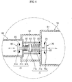
- the water feed pipe 60 further includes a third packing 90, which is provided on a front end of the insert part 61 of the water feed pipe 60, to seal the water path defined by the insert part 61 when the water feed tank 50 is securely coupled to the water feed pipe 60 as shown in FIG. 4.
- the insert part 61 of the water feed pipe 60 is inserted into the receiver 52 of the water feed tank 50, so that the first outside part 71b of the first valve 70 and the second outside part 81b of the second valve 80 are in contact with each other to be compressed in opposite directions.
- the first elastic unit 72 and the second elastic unit 82 are compressed, the first valve 70 and the second valve 80 open. Because the second elastic unit 82 has an elastic modulus lower than the first elastic unit 72, the second valve 80 is opened prior an opening of the first valve 70.
- the receiver 52 of the water feed tank 50 is bent at an end thereof toward an axis of the receiver 52 to prevent the water from leaking from the end of the receiver 52 while the water feed tank 50 is removed from the water feed pipe 60.
- the operation and effect of the heating cooker 100 of the present invention will be described herein below.
- the heating cooker 100 is operated so that the first heater 30 heats air in the cooking cavity 20.
- the air heated by the first heater 30 is circulated within the cooking cavity 20 by an operation of the fan 31 to the foods.
- the water, contained in the steam generating vessel 41 is heated by the second heater 42 of the steam generator 40 to generate steam.
- the steam generated from the steam generator 40 is supplied into the cooking cavity 20.
- the water feed tank 50 which contains water therein, is coupled to the water feed pipe 60.
- the first and second valves 71 and 81 close the outlet 53 of the water feed tank 50 and the inlet 62 of the water feed pipe 60 by restoring forces of the first and second elastic units 72 and 82, respectively.
- the first outside part 71b of the first valve 70 is in contact with the second outside part 81b of the second valve 80.
- the second valve 80 When the water feed tank 50 is further inserted into the casing 10, the second valve 80 is opened prior to the opening of the first valve 70 because the elastic modulus of the second elastic unit 82 is lower than the elastic modulus of the first elastic unit 72, as shown in FIG. 3. Thereafter, when the water feed tank 50 is still further inserted into the casing 10, the first valve 70 also opens, as shown in FIG. 4, so that the water is discharged from the water feed tank 50 into the water feed pipe 60. Where the water feed tank 50 is fully inserted into the casing 10, the front end of the insert part 61 of the water feed pipe 60 is in contact with the rear end of the tank part 51 of the water feed tank 50, so that the water path passes through the outlet 53 of the water feed tank 50 and the inlet 62 of the water feed pipe 60. Thus, the water discharged from the tank part 51 is introduced into the water feed pipe 60 through the above-mentioned water path without substantial leakage.
- the first valve 70 is primarily closed to stop the discharging of the water from the water feed tank 50.
- the second valve 80 is closed to prevent the water from flowing from the water feed pipe 60 in a reverse direction.
- a heating cooker of the present invention includes a second valve to control an inlet of a water feed pipe. Therefore, even though the inlet of the water feed pipe is placed in the heating cooker in any direction, water contained in the water feed pipe does not leak from the inlet of the water feed pipe. Furthermore, a water feed tank moves to or away from the water feed pipe in a front part of a casing to be coupled to or removed from the water feed pipe, so that the structure of the heating cooker of the present invention is more convenient to a user because the user needs not pick up and put down the heavy water feed tank onto the casing to couple the water feed tank to the water feed pipe.
Landscapes
- Engineering & Computer Science (AREA)
- Chemical & Material Sciences (AREA)
- Combustion & Propulsion (AREA)
- Mechanical Engineering (AREA)
- General Engineering & Computer Science (AREA)
- Cookers (AREA)
- Electric Ovens (AREA)
Claims (21)
- Appareil de cuisson chauffant (100), comprenant :- un générateur de vapeur (40) pour fournir de la vapeur dans une cavité de cuisson (20) définie dans l'appareil de cuisson chauffant (100) ;- un réservoir d'alimentation en eau (50) pour fournir de l'eau dans le générateur de vapeur (40) ;- un tube d'alimentation en eau (60) pour fournir de l'eau du réservoir d'alimentation en eau (50) dans le générateur de vapeur (40), le réservoir d'alimentation en eau (50) étant couplé de manière amovible au tube d'alimentation en eau (60); caractérisé en ce qu'il comprend en outre :- un premier clapet (70) pour réguler une sortie (53) prévue sur le réservoir d'alimentation en eau (50) pour évacuer l'eau du réservoir d'alimentation en eau (50) ; et- un deuxième clapet (80) pour réguler une entrée (62) prévue sur le tube d'alimentation en eau (60) pour aspirer l'eau évacuée du réservoir d'alimentation en eau (50) dans le tube d'alimentation en eau (60), le premier clapet (70) comprenant :- un premier corps de clapet (71) pour réguler la sortie (53) du réservoir d'alimentation en eau (50) ; et- une première unité élastique (72) pour supporter le premier corps de clapet (71), et- le deuxième clapet (80) comprenant :- un deuxième corps de clapet (81) pour réguler l'entrée (54) du tube d'alimentation en eau (60) ; et- une deuxième unité élastique (82) pour supporter le deuxième corps de clapet (81),
la première unité élastique (72) présentant un coefficient élastique supérieur à celui de la deuxième unité élastique (82). - Appareil de cuisson chauffant (100) selon la revendication 1, dans lequel le premier clapet (70) et le deuxième clapet (80) sont aptes à être respectivement ouverts pendant que le réservoir d'alimentation en eau (50) est couplé au tube d'alimentation en eau (60), et le premier clapet (70) et le deuxième clapet (80) sont aptes à être respectivement fermés pendant que le réservoir d'alimentation en eau (50) est déposé du tube d'alimentation en eau (60).
- Appareil de cuisson chauffant (100) selon la revendication 2, dans lequel le premier clapet (70) et le deuxième clapet (80) se régulent mutuellement pour ouvrir ou fermer le deuxième clapet (80) et le premier clapet (70).
- Appareil de cuisson chauffant (100) selon l'une quelconque des revendications précédentes, dans lequel le premier corps de clapet (71) et le deuxième corps de clapet (81) ont des emplacements correspondants respectifs aux extrémités extérieures du premier corps de clapet (71) et du deuxième corps de clapet (81).
- Appareil de cuisson chauffant (100) selon l'une quelconque des revendications précédentes, dans lequel la première unité élastique (72) supporte le premier corps de clapet (71) vers un extérieur du réservoir d'alimentation en eau (50), et la deuxième unité élastique (82) supporte le deuxième corps de clapet (81) vers un extérieur du tube d'alimentation en eau (60).
- Appareil de cuisson chauffant (100) selon l'une quelconque des revendications précédentes, dans lequel chacune parmi la première unité élastique (72) et la deuxième unité élastique (82) est un ressort de compression.
- Appareil de cuisson chauffant (100) selon la revendication 6, dans lequel le premier corps de clapet (71) comprend :- une première partie intérieure (71a) à un intérieur de la sortie (53) du réservoir d'alimentation en eau (50) ;- une première partie extérieure (71b) à un extérieur de la sortie (53) du réservoir d'alimentation en eau (50) ; et- une première partie intermédiaire (71c) pour relier la première partie intérieure (71a) à la première partie extérieure (71b), et- le deuxième corps de clapet (81) comprend:- une deuxième partie intérieure (81a) à un intérieur de l'entrée (54) du tube d'alimentation en eau (60) ;- une deuxième partie extérieure (81b) à un extérieur de l'entrée (54) du tube d'alimentation en eau (60) ; et- une deuxième partie intermédiaire (81c) pour relier la deuxième partie intérieure (81 a) à la deuxième partie extérieure (81 b).
- Appareil de cuisson chauffant (100) selon la revendication 7, comprenant en outre :- une première garniture d'étanchéité (73) sur la première partie intérieure (71a) du premier corps de clapet à déplacement alterné (71) pour assurer l'étanchéité de la sortie (53) du réservoir d'alimentation en eau (50) ; et- une deuxième garniture d'étanchéité (83) sur la deuxième partie intérieure (81a) du deuxième corps de clapet à déplacement alterné (81) pour assurer l'étanchéité de l'entrée (54) du tube d'alimentation en eau (60).
- Appareil de cuisson chauffant (100) selon l'une quelconque des revendications précédentes, comprenant en outre :- une voie d'écoulement d'eau entre la sortie (53) du réservoir d'alimentation en eau (50) et l'entrée (62) du tube d'alimentation en eau (60) pour guider l'eau de la sortie (53) vers l'entrée (62).
- Appareil de cuisson chauffant (100) selon la revendication 9, dans lequel la voie d'écoulement d'eau comprend une partie d'insert (61) s'étendant à partir du tube d'alimentation en eau (60).
- Appareil de cuisson chauffant (100) selon la revendication 10, comprenant en outre :- une troisième garniture d'étanchéité (90) prévue sur la partie d'insert (61) du tube d'alimentation en eau (60) pour assurer l'étanchéité de la voie d'écoulement d'eau.
- Appareil de cuisson chauffant (100) selon la revendication 11, dans lequel le réservoir d'alimentation en eau (50) comprend en outre un récepteur (52) pour recevoir la partie d'insert (61) du tube d'alimentation en eau (60).
- Appareil de cuisson chauffant (100) selon la revendication 12, dans lequel le récepteur (52) du réservoir d'alimentation en eau (50) est replié à l'une de ses extrémités vers un axe longitudinal du récepteur (52).
- Appareil de cuisson chauffant (100) selon la revendication 13, adapté de sorte que, lorsque le réservoir d'alimentation en eau (50) est couplé au tube d'alimentation en eau (60), la partie d'insert (61) du tube d'alimentation en eau (60) soit insérée dans le récepteur (52) de sorte que la première partie extérieure (71b) du premier clapet (70) et la deuxième partie extérieure (81b) du deuxième clapet (80) soient en contact l'une avec l'autre.
- Appareil de cuisson chauffant (100) selon la revendication 13, adapté de sorte que, lorsque le réservoir d'alimentation en eau (50) est couplé au tube d'alimentation en eau (60), la partie d'insert (61) du tube d'alimentation en eau (60) soit insérée dans le récepteur (52) de sorte que la première partie extérieure (71b) du premier clapet (70) et la deuxième partie extérieure (81b) du deuxième clapet (80) pressent le premier clapet (70) et le deuxième clapet (80) dans des directions opposées.
- Appareil de cuisson chauffant (100) selon la revendication 13, adapté de sorte que, lorsque le réservoir d'alimentation en eau (50) est séparé du tube d'alimentation en eau (60) avant que le réservoir d'alimentation en eau (50) ne soit couplé au tube d'alimentation en eau (60), le premier clapet (70) et le deuxième clapet (80) ferment la sortie (53) du réservoir d'alimentation en eau (50) et l'entrée (54) du tube d'alimentation en eau (60) en rétablissant les forces exercées par la première unité élastique (72) et par la deuxième unité élastique (82).
- Appareil de cuisson chauffant (100) selon la revendication 13, dans lequel, parce que le coefficient élastique de la deuxième unité élastique (82) est inférieur au coefficient élastique de la première unité élastique (72), lorsque le réservoir d'alimentation en eau (50) est couplé au tube d'alimentation en eau (60), le deuxième clapet (80) est apte à être ouvert avant l'instant où le premier clapet (70) s'ouvre.
- Appareil de cuisson chauffant (100) selon la revendication 15, adapté de sorte que, lorsque le réservoir d'alimentation en eau (50) est découplé du tube d'alimentation en eau (60), le premier clapet (70) est fermé avant que le deuxième clapet (80) ne soit fermé.
- Appareil de cuisson chauffant (100) selon la revendication 18, adapté de sorte que, après que le réservoir d'alimentation en eau (50) est découplé du tube d'alimentation en eau (60), l'eau restant dans la partie d'insert (61) du tube d'alimentation en eau (60) est évacuée.
- Appareil de cuisson chauffant (100) selon l'une quelconque des revendications précédentes, dans lequel la sortie (53) du réservoir d'alimentation en eau (50) et l'entrée (62) du tube d'alimentation en eau (60) se font face dans une direction horizontale, et le réservoir d'alimentation en eau (50) est apte à se déplacer pour se rapprocher ou s'éloigner du tube d'alimentation en eau (60) dans la direction horizontale pour être couplé au ou déposé du tube d'alimentation en eau (60).
- Appareil de cuisson chauffant (100) selon la revendication 20, dans lequel le réservoir d'alimentation en eau (50) est prévu à une portion prédéterminée dans une partie frontale de l'appareil de cuisson chauffant (100).
Applications Claiming Priority (2)
| Application Number | Priority Date | Filing Date | Title |
|---|---|---|---|
| KR1020030092198A KR20050060560A (ko) | 2003-12-16 | 2003-12-16 | 가열조리기 |
| KR2003092198 | 2003-12-16 |
Publications (2)
| Publication Number | Publication Date |
|---|---|
| EP1543754A1 EP1543754A1 (fr) | 2005-06-22 |
| EP1543754B1 true EP1543754B1 (fr) | 2007-08-01 |
Family
ID=34511236
Family Applications (1)
| Application Number | Title | Priority Date | Filing Date |
|---|---|---|---|
| EP04255510A Expired - Lifetime EP1543754B1 (fr) | 2003-12-16 | 2004-09-11 | Appareil de cuisson |
Country Status (5)
| Country | Link |
|---|---|
| US (1) | US6972397B2 (fr) |
| EP (1) | EP1543754B1 (fr) |
| KR (1) | KR20050060560A (fr) |
| CN (1) | CN1308626C (fr) |
| DE (1) | DE602004007867T2 (fr) |
Families Citing this family (37)
| Publication number | Priority date | Publication date | Assignee | Title |
|---|---|---|---|---|
| TWI314768B (en) * | 2003-09-04 | 2009-09-11 | United Microelectronics Corp | Method of manufacturing metal-oxide-semiconductor transistor |
| KR101132331B1 (ko) | 2004-07-14 | 2012-04-05 | 삼성전자주식회사 | 가열조리장치 및 그 제어방법 |
| US7208702B2 (en) * | 2004-11-22 | 2007-04-24 | Goodway Electrical Co., Ltd. | Steam cooker |
| US20060251785A1 (en) | 2005-05-06 | 2006-11-09 | Stefania Fraccon | Method for cooking food using steam |
| FR2887967B1 (fr) * | 2005-07-01 | 2007-08-17 | Seb Sa | Dispositif d'evaporation d'eau |
| KR101085901B1 (ko) | 2006-09-28 | 2011-11-23 | 삼성전자주식회사 | 가열조리기 |
| KR100762269B1 (ko) * | 2006-09-28 | 2007-10-01 | 삼성전자주식회사 | 가열조리장치 |
| US7867534B2 (en) * | 2006-10-18 | 2011-01-11 | Whirlpool Corporation | Cooking appliance with steam generator |
| DE102006050368B4 (de) * | 2006-10-25 | 2022-08-25 | BSH Hausgeräte GmbH | Gargerät zum Garen von Lebensmitteln mittels Dampf |
| KR100824006B1 (ko) * | 2006-12-29 | 2008-04-24 | 엘지전자 주식회사 | 스팀 오븐의 스팀 발생장치 |
| US8689462B2 (en) * | 2007-04-25 | 2014-04-08 | Lg Electronics Inc. | Steam laundry dryer |
| KR101396971B1 (ko) * | 2007-05-02 | 2014-05-20 | 엘지전자 주식회사 | 스팀건조기 |
| US20090136640A1 (en) * | 2007-11-26 | 2009-05-28 | Whirlpool Corporation | Method for Baking a Casserole Using Steam |
| EP2420732A1 (fr) * | 2009-04-16 | 2012-02-22 | Sharp Kabushiki Kaisha | Réservoir de liquide et appareil de cuisson |
| WO2011083757A1 (fr) * | 2010-01-07 | 2011-07-14 | パナソニック株式会社 | Cuiseur avec fonction de génération de vapeur |
| FR2958720B1 (fr) * | 2010-04-09 | 2014-08-29 | Fagorbrandt Sas | Four de cuisson comprenant des elements de rappel elastique de guidage d'un tiroir de remplissage d'eau. |
| EP2390579A1 (fr) * | 2010-05-28 | 2011-11-30 | Electrolux Home Products Corporation N.V. | Réservoir d'eau pour cavité de four d'un four de cuisson |
| DE102011110784A1 (de) * | 2011-01-24 | 2012-07-26 | Convotherm Elektrogeräte GmbH | Über-/Unterdruckventil für einen Stutzen an einem Gargerät, Stutzen sowie Gargerät |
| US20130264327A1 (en) * | 2012-04-05 | 2013-10-10 | Yao-Tsung Kao | Household Atomized Oven |
| ITMI20121879A1 (it) * | 2012-11-05 | 2014-05-06 | Ma Ti Ka S R L | Pannello per forno |
| EP2896737B1 (fr) | 2014-01-15 | 2017-03-22 | Electrolux Appliances Aktiebolag | Alimentation en fluide pour un appareil électroménager et ledit appareil |
| US12281801B2 (en) * | 2014-07-29 | 2025-04-22 | Conair Llc | Combination heat and steam oven |
| CN110200516A (zh) | 2017-08-09 | 2019-09-06 | 沙克忍者运营有限责任公司 | 烹饪系统 |
| CN107307727A (zh) * | 2017-08-11 | 2017-11-03 | 陕西科弘实业发展有限公司 | 屉式食品蒸釜 |
| DE102017214928A1 (de) * | 2017-08-25 | 2019-02-28 | BSH Hausgeräte GmbH | Dampfgargerät |
| DE102017214932A1 (de) * | 2017-08-25 | 2019-02-28 | BSH Hausgeräte GmbH | Dampfgargerät |
| EP3575695B1 (fr) | 2018-05-28 | 2023-05-17 | Renta Elektrikli Ev Aletleri Sanayi Ve Dis Ticaret Limited Sirketi | Charnière à couple réglable pour portes ayant différents poids |
| US10955142B2 (en) | 2018-07-03 | 2021-03-23 | Electrolux Home Products, Inc. | Cooking oven with steam generator inside cooking cavity |
| WO2020176477A1 (fr) | 2019-02-25 | 2020-09-03 | Sharkninja Operating Llc | Système de cuisson avec protection |
| US11033146B2 (en) | 2019-02-25 | 2021-06-15 | Sharkninja Operating Llc | Cooking device and components thereof |
| CN110448163B (zh) * | 2019-08-28 | 2021-03-19 | 广东美的厨房电器制造有限公司 | 水盒组件及家用电器 |
| CN112790597B (zh) * | 2019-11-14 | 2022-03-18 | 宁波方太厨具有限公司 | 一种带蒸功能的烹饪设备 |
| US11647861B2 (en) | 2020-03-30 | 2023-05-16 | Sharkninja Operating Llc | Cooking device and components thereof |
| EP4019852A1 (fr) * | 2020-12-24 | 2022-06-29 | Koninklijke Philips N.V. | Appareil de cuisson à la vapeur |
| DE102021201865A1 (de) | 2021-02-26 | 2022-09-01 | BSH Hausgeräte GmbH | Wasserführendes Haushaltsgerät und Anschlussstecker |
| EP4327026B1 (fr) * | 2021-06-21 | 2026-01-21 | Gorenje d.o.o. | Four avec un dispositif de génération de vapeur et procédé de fonctionnement d'un four |
| US12529481B2 (en) * | 2022-01-06 | 2026-01-20 | Whirlpool Corporation | Water fill drawer with structures to prevent backflow of steam |
Family Cites Families (12)
| Publication number | Priority date | Publication date | Assignee | Title |
|---|---|---|---|---|
| JPS58194747U (ja) * | 1982-06-18 | 1983-12-24 | 大畠 隆 | 加工食品保管庫 |
| EP0277337B1 (fr) * | 1987-02-05 | 1991-09-18 | Electrolux-Juno Küchentechnik GmbH | Appareil à cuire ayant un espace à cuire chauffé par électricité et procédé pour opérer cet appareil à cuire |
| JPH04123790A (ja) * | 1990-09-14 | 1992-04-23 | Mitsubishi Electric Home Appliance Co Ltd | 水蒸気発生装置付き加熱調理器 |
| JPH06272866A (ja) * | 1993-03-16 | 1994-09-27 | Fuji Mc:Kk | 複合型加熱装置 |
| US5525782A (en) * | 1993-11-11 | 1996-06-11 | Matsushita Electric Industrial Co., Ltd. | Electric combination oven with humidity conditioner |
| NO179883C (no) * | 1994-10-14 | 1997-01-08 | Ulstein Turbine As | Drivstoff-/luftblandingsanordning |
| US5515773A (en) * | 1995-02-16 | 1996-05-14 | The Rival Company | Steam oven |
| US5680810A (en) * | 1996-08-09 | 1997-10-28 | Sham; John C. K. | Steam toaster oven |
| US6232587B1 (en) * | 1996-09-03 | 2001-05-15 | Matsushita Electric Industrial Co., Ltd. | Microwave heating apparatus with a vapor generator and regenerating plates |
| US6100502A (en) * | 1998-10-28 | 2000-08-08 | Wing Shing Products (Bvi) Co. Ltd. | Toaster oven with steam |
| WO2001034008A1 (fr) * | 1999-11-12 | 2001-05-17 | Rolland Versini | Machine a cafe automatique utilisable pour le cafe moulu ou en grains |
| US6267046B1 (en) * | 2000-02-28 | 2001-07-31 | Conair Corporation | Convection steamer |
-
2003
- 2003-12-16 KR KR1020030092198A patent/KR20050060560A/ko not_active Ceased
-
2004
- 2004-08-23 US US10/923,015 patent/US6972397B2/en not_active Expired - Lifetime
- 2004-08-31 CN CNB2004100683438A patent/CN1308626C/zh not_active Expired - Fee Related
- 2004-09-11 DE DE602004007867T patent/DE602004007867T2/de not_active Expired - Lifetime
- 2004-09-11 EP EP04255510A patent/EP1543754B1/fr not_active Expired - Lifetime
Also Published As
| Publication number | Publication date |
|---|---|
| CN1629543A (zh) | 2005-06-22 |
| CN1308626C (zh) | 2007-04-04 |
| US6972397B2 (en) | 2005-12-06 |
| DE602004007867D1 (de) | 2007-09-13 |
| KR20050060560A (ko) | 2005-06-22 |
| DE602004007867T2 (de) | 2008-04-30 |
| US20050127061A1 (en) | 2005-06-16 |
| EP1543754A1 (fr) | 2005-06-22 |
Similar Documents
| Publication | Publication Date | Title |
|---|---|---|
| US6972397B2 (en) | Heating cooker | |
| EP1616516B1 (fr) | Appareil de cuisson et procédé pour sa commande | |
| EP1514475B1 (fr) | Four à vapeur | |
| US7323662B2 (en) | Heating apparatus for cooking | |
| US11078697B2 (en) | Home appliance | |
| EP2993416B1 (fr) | Appareil de cuisson | |
| EP1550828B1 (fr) | Cuisinière à chauffage avec générateur de vapeur | |
| CN101152049B (zh) | 蒸汽发生器和具有其的加热烹饪设备 | |
| EP1517092A1 (fr) | Four à vapeur surchauffée et son procédé de commande | |
| KR102133286B1 (ko) | 조리실의 자동 세척이 가능한 전자 조리 기기 | |
| EP1538396B1 (fr) | Appareil de cuisson | |
| KR101480462B1 (ko) | 스팀 오븐 | |
| CN118338819A (zh) | 具有蒸汽处理抽屉的家用蒸汽烹饪设备 | |
| US6992268B2 (en) | Steam oven having an inner casing including a vacuum | |
| KR20050019446A (ko) | 전자렌지 | |
| EP3619384B1 (fr) | Appareil ménager | |
| KR102120178B1 (ko) | 조리 장치 | |
| KR20030079527A (ko) | 스팀오븐기의 물받이장치 | |
| JP5405186B2 (ja) | 加熱調理器 | |
| KR102124104B1 (ko) | 조리기기 | |
| JP7851869B2 (ja) | 架台 | |
| KR101554041B1 (ko) | 스팀발생장치 | |
| US12546479B2 (en) | Modular steam cooking system for a home cooking appliance | |
| KR20190129632A (ko) | 조리 장치 | |
| KR100634794B1 (ko) | 가열조리장치 |
Legal Events
| Date | Code | Title | Description |
|---|---|---|---|
| PUAI | Public reference made under article 153(3) epc to a published international application that has entered the european phase |
Free format text: ORIGINAL CODE: 0009012 |
|
| AK | Designated contracting states |
Kind code of ref document: A1 Designated state(s): AT BE BG CH CY CZ DE DK EE ES FI FR GB GR HU IE IT LI LU MC NL PL PT RO SE SI SK TR |
|
| AX | Request for extension of the european patent |
Extension state: AL HR LT LV MK |
|
| 17P | Request for examination filed |
Effective date: 20051207 |
|
| AKX | Designation fees paid |
Designated state(s): DE FR GB |
|
| 17Q | First examination report despatched |
Effective date: 20051230 |
|
| GRAP | Despatch of communication of intention to grant a patent |
Free format text: ORIGINAL CODE: EPIDOSNIGR1 |
|
| GRAS | Grant fee paid |
Free format text: ORIGINAL CODE: EPIDOSNIGR3 |
|
| GRAA | (expected) grant |
Free format text: ORIGINAL CODE: 0009210 |
|
| AK | Designated contracting states |
Kind code of ref document: B1 Designated state(s): DE FR GB |
|
| REG | Reference to a national code |
Ref country code: GB Ref legal event code: FG4D |
|
| REF | Corresponds to: |
Ref document number: 602004007867 Country of ref document: DE Date of ref document: 20070913 Kind code of ref document: P |
|
| ET | Fr: translation filed | ||
| PLBE | No opposition filed within time limit |
Free format text: ORIGINAL CODE: 0009261 |
|
| STAA | Information on the status of an ep patent application or granted ep patent |
Free format text: STATUS: NO OPPOSITION FILED WITHIN TIME LIMIT |
|
| 26N | No opposition filed |
Effective date: 20080506 |
|
| PGFP | Annual fee paid to national office [announced via postgrant information from national office to epo] |
Ref country code: DE Payment date: 20130828 Year of fee payment: 10 |
|
| REG | Reference to a national code |
Ref country code: DE Ref legal event code: R119 Ref document number: 602004007867 Country of ref document: DE |
|
| REG | Reference to a national code |
Ref country code: DE Ref legal event code: R119 Ref document number: 602004007867 Country of ref document: DE Effective date: 20150401 |
|
| PG25 | Lapsed in a contracting state [announced via postgrant information from national office to epo] |
Ref country code: DE Free format text: LAPSE BECAUSE OF NON-PAYMENT OF DUE FEES Effective date: 20150401 |
|
| REG | Reference to a national code |
Ref country code: FR Ref legal event code: PLFP Year of fee payment: 13 |
|
| REG | Reference to a national code |
Ref country code: FR Ref legal event code: PLFP Year of fee payment: 14 |
|
| PGFP | Annual fee paid to national office [announced via postgrant information from national office to epo] |
Ref country code: FR Payment date: 20170824 Year of fee payment: 14 Ref country code: GB Payment date: 20170823 Year of fee payment: 14 |
|
| GBPC | Gb: european patent ceased through non-payment of renewal fee |
Effective date: 20180911 |
|
| PG25 | Lapsed in a contracting state [announced via postgrant information from national office to epo] |
Ref country code: FR Free format text: LAPSE BECAUSE OF NON-PAYMENT OF DUE FEES Effective date: 20180930 |
|
| PG25 | Lapsed in a contracting state [announced via postgrant information from national office to epo] |
Ref country code: GB Free format text: LAPSE BECAUSE OF NON-PAYMENT OF DUE FEES Effective date: 20180911 |