EP1542166A1 - Verfahren und Vorrichtung zur dreidimensionalen Rückprojektion und Röntgenstrahlencomputertomograph - Google Patents
Verfahren und Vorrichtung zur dreidimensionalen Rückprojektion und Röntgenstrahlencomputertomograph Download PDFInfo
- Publication number
- EP1542166A1 EP1542166A1 EP04257583A EP04257583A EP1542166A1 EP 1542166 A1 EP1542166 A1 EP 1542166A1 EP 04257583 A EP04257583 A EP 04257583A EP 04257583 A EP04257583 A EP 04257583A EP 1542166 A1 EP1542166 A1 EP 1542166A1
- Authority
- EP
- European Patent Office
- Prior art keywords
- plane
- projected
- data
- ray
- lines
- Prior art date
- Legal status (The legal status is an assumption and is not a legal conclusion. Google has not performed a legal analysis and makes no representation as to the accuracy of the status listed.)
- Granted
Links
Images






Classifications
-
- A—HUMAN NECESSITIES
- A61—MEDICAL OR VETERINARY SCIENCE; HYGIENE
- A61B—DIAGNOSIS; SURGERY; IDENTIFICATION
- A61B6/00—Apparatus or devices for radiation diagnosis; Apparatus or devices for radiation diagnosis combined with radiation therapy equipment
- A61B6/02—Arrangements for diagnosis sequentially in different planes; Stereoscopic radiation diagnosis
- A61B6/03—Computed tomography [CT]
-
- G—PHYSICS
- G06—COMPUTING OR CALCULATING; COUNTING
- G06T—IMAGE DATA PROCESSING OR GENERATION, IN GENERAL
- G06T12/00—Tomographic reconstruction from projections
- G06T12/20—Inverse problem, i.e. transformations from projection space into object space
Definitions
- the present invention relates to a three-dimensional back-projection method and apparatus, and an X-ray CT (computed tomography) apparatus, and to image reconstruction according to a three-dimensional back-projection method in a conventional scan (axial scan).
- Patent Document 1 Japanese Patent Application Laid Open No. 2003-225230 (pages 9 - 10, Figures 1 - 2)
- the image reconstruction based on the three-dimensional back-projection method generally poses a problem in that it requires a larger amount of calculation than that of image reconstruction based on two-dimensional back-projection, and is more time-consuming.
- the present invention seeks to provide a three-dimensional back-projection method and apparatus that requires a smaller amount of calculation and is less time-consuming, and an X-ray CT apparatus comprising such a three-dimensional back-projection apparatus.
- the number of plane-projected data lines is optimized taking image quality of an image to be reconstructed into account, so that the amount of calculation can be optimized according to target image quality.
- said projection plane is defined as the x-z plane that passes through a center of rotation for -45° ⁇ rotation angle ⁇ 45° or a rotation angle range mainly including the range and also including its vicinity and 135° ⁇ rotation angle ⁇ 225° or a rotation angle range mainly including the range and also including its vicinity, and said projection plane is defined as the y-z plane that passes through the center of rotation for 45° ⁇ rotation angle ⁇ 135° or a rotation angle range mainly including the range and also including its vicinity and 225° ⁇ rotation angle ⁇ 315° or a rotation angle range mainly including the range and also including its vicinity, so that the
- the plane-projected data D1 is projected in a direction of X-ray transmission onto pixels constituting a plurality of lines arranged successively in a direction parallel to the projection plane at spacings of a plurality of pixels on a reconstruction field, to determine back-projected pixel data D2 for pixels constituting lines on the reconstruction field for a number of plane-projected data lines that depends upon the angle formed between the plane of the reconstruction field and X-ray beam, and therefore, the number of plane-projected data lines is decreased for a smaller angle between the plane of the reconstruction field and X-ray beam, thus reducing the amount of calculation.
- a three-dimensional back-projection method and apparatus and an X-ray CT apparatus characterized in that they control or optimize the time for reconstruction by controlling or optimizing the number of lines for planar projection according to the cone angle formed between the reconstruction plane (X-Y plane) and X-ray beam.
- the time for reconstruction is reduced by decreasing the number of lines for planar projection for a smaller cone angle formed between the reconstruction plane (X-Y plane) and X-ray beam, and increasing it for a larger cone angle.
- Figure 1 shows a block diagram of an X-ray CT apparatus.
- the present apparatus is an example of the best mode for carrying out the present invention.
- the configuration of the present apparatus represents an example of the best mode for carrying out the present invention with respect to the three-dimensional back-projection apparatus or X-ray CT apparatus of the present invention.
- the operation of the present apparatus represents an example of the best mode for carrying out the present invention with respect to the three-dimensional back-projection method of the present invention.
- the X-ray CT apparatus 100 comprises an operation console 1, an imaging table 10, and a scan gantry 20.
- the operation console 1 comprises an input device 2 for accepting inputs by a human operator, a central processing apparatus 3 for executing three-dimensional back-projection processing in accordance with the present invention etc., a data collection buffer 5 for collecting projection data acquired at the scan gantry 20, a CRT 6 for displaying a CT image reconstructed from the projection data, and a storage device 7 for storing programs, data, and X-ray CT images.
- the table apparatus 10 comprises a cradle 12 for laying thereon a subject and transporting the subject into/out of a bore (cavity portion) of the scan gantry 20.
- the cradle 12 is driven by a motor built in the table apparatus 10.
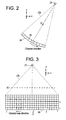
- Figures 2 and 3 are explanatory diagrams of the X-ray tube 21 and multi-row detector 24.
- the X-ray tube 21 and multi-row detector 24 rotate around a center of rotation IC. Representing the vertical direction as y-direction, the horizontal direction as x-direction, and a direction perpendicular to these directions as z-direction, the plane of rotation of the X-ray tube 21 and multi-row detector 24 is the x-y plane.
- the direction of translation of the cradle 12 is the z-direction.
- a planar X-ray detector may be employed.
- the X-ray tube 21 generates an X-ray beam generally referred to as cone beam CB.
- the multi-row detector 24 has 256 detector rows, for example. Each detector row has 1,024 channels, for example.
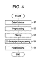
- Figure 4 is a flow chart showing the general operation of the X-ray CT apparatus 100.
- Step S1 projection data D0(z, view, j, i) represented by the table's rectilinear motion position z, view angle view, detector row index j and channel index i is collected while rotating the X-ray tube 21 and multi-row detector 24 around the subject to be imaged.
- the data collection is conducted by the scan gantry 20.
- the scan gantry 20 is an example of the scanning means of the present invention
- the projection data D0( z , view, j, i ) is subjected to pre-processing (offset correction, log correction, X-ray dose correction and sensitivity correction).
- the pre-processed projection data D0(z, view, j, i) is filtered. Specifically, the data is subjected to Fourier transformation, multiplied by a filter (reconstruction function), and then subjected to inverse Fourier transformation.
- the filtered projection data D0(z, view, j, i ) is subjected to three-dimensional back-projection processing to determine back-projected data D3( x , y).
- the three-dimensional back-projection processing will be discussed below with reference to Figure 5.
- the back-projected data D3( x , y ) is subjected to post-processing to obtain a CT image.
- Figure 6 exemplarily shows a plurality of parallel lines L0 - L8 on the reconstruction field P.
- the number of lines is 1/64 - 1/2 of the maximum number of pixels in the reconstruction field in a direction orthogonal to the lines. For example, if the number of pixels in the reconstruction field P is 512x512, the number of lines is nine.
- Figure 7 shows lines T0 - T8 formed by projecting the plurality of parallel lines L0 - L8 onto a detector plane dp in the direction of X-ray transmission.
- the direction of X-ray transmission is determined depending upon the geometrical position of the X-ray tube 21, multi-row detector 24 and lines L0 - L8 (including the distance in the z-axis direction from the x-y plane passing through the center in the z-axis direction of the multi-row detector 24 to the image reconstruction field P, and the positions of the lines L0 - L8 formed by a set of pixel points on the image reconstruction plane P); since the position z of the projection data D0(z, view, j, i ) in the direction of the table's rectilinear motion is known, the direction of X-ray transmission can be accurately determined.
- the projection data Dr corresponding to the lines L0 - L8 can be obtained by extracting projection data at the detector row j and channel i corresponding to the lines T0 - T8 projected onto the detector plane dp .
- the projection data Dr is obtained by interpolation or extrapolation, if necessary.
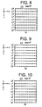
- the projection data Dr of the lines L0' - L8' are multiplied by a cone beam reconstruction weight to generate projection line data Dp as shown in Figure 9.
- the cone beam reconstruction weight is ( r 1/ r 0) 2 , where r 0 is the distance from the focal spot of the X-ray tube 21 to the j -th detector row and the i -th channel of the multi-row detector 24 corresponding to projection data Dr, and r 1 is the distance from the focal spot of the X-ray tube 21 to a point on the reconstruction field corresponding to the projection data Dr.
- the projection line data Dp are filtered. Specifically, the projection line data Dp are subjected to FFT, multiplied by a filter function (reconstruction function), and subjected to inverse FFT to generate image-positional line data Df as shown in Figure 10.
- the image-positional line data Df is interpolated in the line direction to generate high-density image-positional line data Dh as shown in Figure 11.
- the data density of the high-density image-positional line data Dh is 8 - 32 times the maximum number of pixels in the reconstruction field in the line direction. For example, if the factor is 16 and the number of pixels in the reconstruction field P is 512x512, the data density is 8,192 points/line.
- the central processing apparatus 3 conducting the processing from Step R1 to R5 is an example of the plane-projected data calculating means of the present invention.
- Step R6 the high-density image-positional line data Dh are sampled and interpolated/extrapolated, if necessary, to generate back-projected pixel data D2 for pixels on the lines L0 - L8, as shown in Figure 12.
- Step R7 the high-density image-positional line data Dh are sampled and interpolated/extrapolated to generate back-projected pixel data D2 for pixels in between the lines L0 - L8, as shown in Figure 13.
- the central processing apparatus 3 conducting the processing from Step R6 to R7 is an example of the back-projected pixel data calculating means of the present invention.
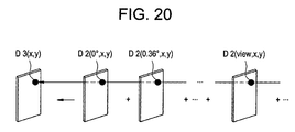
- Step R8 the back-projected pixel data D2 shown in Figure 13 or 19 are added on a pixel-by-pixel basis, as shown in Figure 20.
- Step R9 Steps R1 - R8 are repeated for all views needed in reconstruction of a CT image (i.e., views for 360° or for "180° + fan angle") to obtain back-projected data D3( x , y).
- the central processing apparatus 3 conducting the processing from Step R8 to R9 is an example of the back-projected data calculating means of the present invention.
Landscapes
- Engineering & Computer Science (AREA)
- Health & Medical Sciences (AREA)
- Life Sciences & Earth Sciences (AREA)
- Physics & Mathematics (AREA)
- Medical Informatics (AREA)
- General Physics & Mathematics (AREA)
- Theoretical Computer Science (AREA)
- Optics & Photonics (AREA)
- Heart & Thoracic Surgery (AREA)
- Nuclear Medicine, Radiotherapy & Molecular Imaging (AREA)
- Biophysics (AREA)
- Pathology (AREA)
- Radiology & Medical Imaging (AREA)
- Biomedical Technology (AREA)
- High Energy & Nuclear Physics (AREA)
- Molecular Biology (AREA)
- Surgery (AREA)
- Animal Behavior & Ethology (AREA)
- General Health & Medical Sciences (AREA)
- Public Health (AREA)
- Veterinary Medicine (AREA)
- Apparatus For Radiation Diagnosis (AREA)
Applications Claiming Priority (2)
| Application Number | Priority Date | Filing Date | Title |
|---|---|---|---|
| JP2003411283 | 2003-12-10 | ||
| JP2003411283A JP4222930B2 (ja) | 2003-12-10 | 2003-12-10 | 3次元逆投影方法および装置並びにx線ct装置 |
Publications (2)
| Publication Number | Publication Date |
|---|---|
| EP1542166A1 true EP1542166A1 (de) | 2005-06-15 |
| EP1542166B1 EP1542166B1 (de) | 2007-08-08 |
Family
ID=34510509
Family Applications (1)
| Application Number | Title | Priority Date | Filing Date |
|---|---|---|---|
| EP04257583A Expired - Lifetime EP1542166B1 (de) | 2003-12-10 | 2004-12-06 | Verfahren und Vorrichtung zur dreidimensionalen Rückprojektion und Röntgenstrahlencomputertomograph |
Country Status (6)
| Country | Link |
|---|---|
| US (1) | US20050123091A1 (de) |
| EP (1) | EP1542166B1 (de) |
| JP (1) | JP4222930B2 (de) |
| KR (1) | KR100648758B1 (de) |
| CN (1) | CN1626037A (de) |
| DE (1) | DE602004008017T2 (de) |
Cited By (2)
| Publication number | Priority date | Publication date | Assignee | Title |
|---|---|---|---|---|
| EP1555633A3 (de) * | 2003-12-22 | 2005-11-09 | GE Medical Systems Global Technology Company LLC | Verfahren und Vorrichtung zur CT Bilderzeugung in Vielfachposition |
| WO2011002442A1 (en) * | 2009-06-30 | 2011-01-06 | Analogic Corporation | Efficient quasi-exact 3d image reconstruction algorithm for ct scanners |
Families Citing this family (4)
| Publication number | Priority date | Publication date | Assignee | Title |
|---|---|---|---|---|
| JP4781024B2 (ja) * | 2005-07-08 | 2011-09-28 | 株式会社日立メディコ | X線ct装置及び逆投影演算器 |
| JP2007044207A (ja) * | 2005-08-09 | 2007-02-22 | Ge Medical Systems Global Technology Co Llc | 放射線ct撮影方法およびx線ct装置 |
| CN100464707C (zh) * | 2005-09-16 | 2009-03-04 | 北京大学 | 三维锥束ct图像重建的处理系统 |
| JP6280851B2 (ja) * | 2014-09-30 | 2018-02-14 | ジーイー・メディカル・システムズ・グローバル・テクノロジー・カンパニー・エルエルシー | 放射線断層撮影装置及びプログラム |
Citations (1)
| Publication number | Priority date | Publication date | Assignee | Title |
|---|---|---|---|---|
| EP1445735A1 (de) * | 2003-02-08 | 2004-08-11 | GE Medical Systems Global Technology Company LLC | Verfahren zur dreidimensionalen Rückprojektion und Röntgenstrahlencomputertomograph |
Family Cites Families (19)
| Publication number | Priority date | Publication date | Assignee | Title |
|---|---|---|---|---|
| US4636952A (en) * | 1984-12-03 | 1987-01-13 | General Electric Company | Method and apparatus for back projection image reconstruction using virtual equi-spaced detector array |
| US5253171A (en) * | 1990-09-21 | 1993-10-12 | General Electric Company | Parallel processing method and apparatus based on the algebra reconstruction technique for reconstructing a three-dimensional computerized tomography (CT) image from cone beam projection data |
| US5838756A (en) * | 1996-01-08 | 1998-11-17 | Kabushiki Kaisha Toshiba | Radiation computed tomography apparatus |
| JP3124254B2 (ja) * | 1997-07-24 | 2001-01-15 | ジーイー横河メディカルシステム株式会社 | 放射線断層撮影装置 |
| JP3174288B2 (ja) * | 1997-09-01 | 2001-06-11 | ジーイー横河メディカルシステム株式会社 | Ct画像作成方法およびx線ct装置 |
| US6078638A (en) * | 1998-09-30 | 2000-06-20 | Siemens Corporate Research, Inc. | Pixel grouping for filtering cone beam detector data during 3D image reconstruction |
| US6137856A (en) * | 1998-12-14 | 2000-10-24 | General Electric Company | Generic architectures for backprojection algorithm |
| DE19946092A1 (de) * | 1999-09-25 | 2001-03-29 | Philips Corp Intellectual Pty | Verfahren und Vorrichtung zur Ermittlung eines 3D-Bilddatensatzes eines sich periodisch bewegenden Körperorgans |
| JP2001187046A (ja) * | 1999-12-27 | 2001-07-10 | Ge Medical Systems Global Technology Co Llc | マルチスライスx線ct装置及びその制御方法 |
| US6301325B1 (en) * | 1999-12-22 | 2001-10-09 | Ge Medical Systems Global Technology Company Llc | Half-scan algorithm for use with a high speed multi-row fan beam helical detector |
| US6442228B1 (en) * | 2000-04-20 | 2002-08-27 | Ge Medical Systems Global Technology Company, Llc | Data acquisition modifications for improved reconstruction with conventional CT |
| US6539074B1 (en) * | 2000-08-25 | 2003-03-25 | General Electric Company | Reconstruction of multislice tomographic images from four-dimensional data |
| JP3942142B2 (ja) * | 2000-12-15 | 2007-07-11 | ジーイー・メディカル・システムズ・グローバル・テクノロジー・カンパニー・エルエルシー | 放射線断層撮影装置およびその方法 |
| US6463118B2 (en) * | 2000-12-29 | 2002-10-08 | Ge Medical Systems Global Technology Company, Llc | Computed tomography (CT) weighting for high quality image recontruction |
| JP4175791B2 (ja) * | 2001-08-20 | 2008-11-05 | ジーイー・メディカル・システムズ・グローバル・テクノロジー・カンパニー・エルエルシー | 画像生成方法およびx線ct装置 |
| JP3870105B2 (ja) * | 2002-02-22 | 2007-01-17 | ジーイー・メディカル・システムズ・グローバル・テクノロジー・カンパニー・エルエルシー | 逆投影方法およびx線ct装置 |
| US6724856B2 (en) * | 2002-04-15 | 2004-04-20 | General Electric Company | Reprojection and backprojection methods and algorithms for implementation thereof |
| JP3950782B2 (ja) * | 2002-05-22 | 2007-08-01 | ジーイー・メディカル・システムズ・グローバル・テクノロジー・カンパニー・エルエルシー | 3次元逆投影方法およびx線ct装置 |
| JP2005137390A (ja) * | 2003-11-04 | 2005-06-02 | Ge Medical Systems Global Technology Co Llc | Ct画像生成方法およびx線ct装置 |
-
2003
- 2003-12-10 JP JP2003411283A patent/JP4222930B2/ja not_active Expired - Fee Related
-
2004
- 2004-12-06 EP EP04257583A patent/EP1542166B1/de not_active Expired - Lifetime
- 2004-12-06 DE DE602004008017T patent/DE602004008017T2/de not_active Expired - Fee Related
- 2004-12-09 KR KR1020040103375A patent/KR100648758B1/ko not_active Expired - Fee Related
- 2004-12-10 CN CNA200410100266XA patent/CN1626037A/zh active Pending
- 2004-12-10 US US11/009,751 patent/US20050123091A1/en not_active Abandoned
Patent Citations (1)
| Publication number | Priority date | Publication date | Assignee | Title |
|---|---|---|---|---|
| EP1445735A1 (de) * | 2003-02-08 | 2004-08-11 | GE Medical Systems Global Technology Company LLC | Verfahren zur dreidimensionalen Rückprojektion und Röntgenstrahlencomputertomograph |
Non-Patent Citations (1)
| Title |
|---|
| HEIN I A ET AL: "Double-centering method for increasing efficiency of cone-beam X-ray CT reconstruction", 2001 IEEE NUCLEAR SCIENCE SYMPOSIUM CONFERENCE RECORD. / 2001 IEEE NUCLEAR SCIENCE SYMPOSIUM AND MEDICAL IMAGING CONFERENCE. SAN DIEGO, CA, NOV. 4 - 10, 2001, IEEE NUCLEAR SCIENCE SYMPOSIUM CONFERENCE RECORD, NEW YORK, NY : IEEE, US, vol. 3, 4 November 2001 (2001-11-04), pages 1727 - 1731, XP002278355, ISBN: 0-7803-7324-3 * |
Cited By (4)
| Publication number | Priority date | Publication date | Assignee | Title |
|---|---|---|---|---|
| EP1555633A3 (de) * | 2003-12-22 | 2005-11-09 | GE Medical Systems Global Technology Company LLC | Verfahren und Vorrichtung zur CT Bilderzeugung in Vielfachposition |
| US7519144B2 (en) | 2003-12-22 | 2009-04-14 | Ge Medical Systems Global Technology Company, Llc | Multi-positional CT image producing method and X-ray CT apparatus |
| WO2011002442A1 (en) * | 2009-06-30 | 2011-01-06 | Analogic Corporation | Efficient quasi-exact 3d image reconstruction algorithm for ct scanners |
| US9665953B2 (en) | 2009-06-30 | 2017-05-30 | Analogic Corporation | Efficient quasi-exact 3D image reconstruction algorithm for CT scanners |
Also Published As
| Publication number | Publication date |
|---|---|
| CN1626037A (zh) | 2005-06-15 |
| JP2005168691A (ja) | 2005-06-30 |
| EP1542166B1 (de) | 2007-08-08 |
| KR100648758B1 (ko) | 2006-11-23 |
| DE602004008017D1 (de) | 2007-09-20 |
| US20050123091A1 (en) | 2005-06-09 |
| KR20050056879A (ko) | 2005-06-16 |
| DE602004008017T2 (de) | 2008-04-17 |
| JP4222930B2 (ja) | 2009-02-12 |
Similar Documents
| Publication | Publication Date | Title |
|---|---|---|
| JP3950782B2 (ja) | 3次元逆投影方法およびx線ct装置 | |
| JP4147195B2 (ja) | 3次元逆投影方法およびx線ct装置 | |
| JP2007533390A (ja) | トランケートされた投影と事前に取得した3次元ct画像を用いる円錐ビームct装置 | |
| US20030161433A1 (en) | Backprojection method and X-ray CT apparatus | |
| JP4342164B2 (ja) | コンピュータ断層撮影装置 | |
| CN101401726B (zh) | X射线ct设备 | |
| US7173997B2 (en) | X-ray CT imaging method and X-ray CT apparatus | |
| JP4106251B2 (ja) | 3次元逆投影方法およびx線ct装置 | |
| US20050094760A1 (en) | CT image producing method and X-ray CT apparatus | |
| EP1542166A1 (de) | Verfahren und Vorrichtung zur dreidimensionalen Rückprojektion und Röntgenstrahlencomputertomograph | |
| US7260175B2 (en) | CT image producing method and X-ray CT apparatus | |
| US7209580B2 (en) | Fast computed tomography method | |
| JP5214110B2 (ja) | X線ct装置 | |
| DE102006055934A1 (de) | Auswertungsverfahren für eine Anzahl zweidimensionaler Projektionsbilder eines dreidimensionalen Untersuchungsobjekts | |
| US7519144B2 (en) | Multi-positional CT image producing method and X-ray CT apparatus | |
| JP4363618B2 (ja) | X線ct画像再構成計算方法およびx線ct装置 | |
| JP4156629B2 (ja) | 3次元逆投影方法およびx線ct装置 | |
| JP4884649B2 (ja) | X線ct装置 | |
| KR20070035444A (ko) | X선 ct 장치 |
Legal Events
| Date | Code | Title | Description |
|---|---|---|---|
| PUAI | Public reference made under article 153(3) epc to a published international application that has entered the european phase |
Free format text: ORIGINAL CODE: 0009012 |
|
| AK | Designated contracting states |
Kind code of ref document: A1 Designated state(s): AT BE BG CH CY CZ DE DK EE ES FI FR GB GR HU IE IS IT LI LT LU MC NL PL PT RO SE SI SK TR |
|
| AX | Request for extension of the european patent |
Extension state: AL BA HR LV MK YU |
|
| 17P | Request for examination filed |
Effective date: 20051215 |
|
| AKX | Designation fees paid |
Designated state(s): DE FR GB |
|
| 17Q | First examination report despatched |
Effective date: 20060202 |
|
| GRAP | Despatch of communication of intention to grant a patent |
Free format text: ORIGINAL CODE: EPIDOSNIGR1 |
|
| GRAS | Grant fee paid |
Free format text: ORIGINAL CODE: EPIDOSNIGR3 |
|
| GRAA | (expected) grant |
Free format text: ORIGINAL CODE: 0009210 |
|
| AK | Designated contracting states |
Kind code of ref document: B1 Designated state(s): DE FR GB |
|
| REG | Reference to a national code |
Ref country code: GB Ref legal event code: FG4D |
|
| REF | Corresponds to: |
Ref document number: 602004008017 Country of ref document: DE Date of ref document: 20070920 Kind code of ref document: P |
|
| EN | Fr: translation not filed | ||
| PLBE | No opposition filed within time limit |
Free format text: ORIGINAL CODE: 0009261 |
|
| STAA | Information on the status of an ep patent application or granted ep patent |
Free format text: STATUS: NO OPPOSITION FILED WITHIN TIME LIMIT |
|
| 26N | No opposition filed |
Effective date: 20080509 |
|
| PG25 | Lapsed in a contracting state [announced via postgrant information from national office to epo] |
Ref country code: FR Free format text: LAPSE BECAUSE OF NON-PAYMENT OF DUE FEES Effective date: 20071231 |
|
| PGFP | Annual fee paid to national office [announced via postgrant information from national office to epo] |
Ref country code: DE Payment date: 20090202 Year of fee payment: 5 |
|
| GBPC | Gb: european patent ceased through non-payment of renewal fee |
Effective date: 20081206 |
|
| PG25 | Lapsed in a contracting state [announced via postgrant information from national office to epo] |
Ref country code: GB Free format text: LAPSE BECAUSE OF NON-PAYMENT OF DUE FEES Effective date: 20081206 |
|
| PG25 | Lapsed in a contracting state [announced via postgrant information from national office to epo] |
Ref country code: DE Free format text: LAPSE BECAUSE OF NON-PAYMENT OF DUE FEES Effective date: 20100701 |