EP1541859A1 - Einspritzventil - Google Patents
Einspritzventil Download PDFInfo
- Publication number
- EP1541859A1 EP1541859A1 EP04024922A EP04024922A EP1541859A1 EP 1541859 A1 EP1541859 A1 EP 1541859A1 EP 04024922 A EP04024922 A EP 04024922A EP 04024922 A EP04024922 A EP 04024922A EP 1541859 A1 EP1541859 A1 EP 1541859A1
- Authority
- EP
- European Patent Office
- Prior art keywords
- nozzle needle
- valve
- injection valve
- injection
- pressure
- Prior art date
- Legal status (The legal status is an assumption and is not a legal conclusion. Google has not performed a legal analysis and makes no representation as to the accuracy of the status listed.)
- Granted
Links
- 238000002347 injection Methods 0.000 title claims abstract description 45
- 239000007924 injection Substances 0.000 title claims abstract description 45
- 239000012530 fluid Substances 0.000 claims abstract description 13
- 238000002485 combustion reaction Methods 0.000 description 15
- 239000000446 fuel Substances 0.000 description 14
- 238000013016 damping Methods 0.000 description 6
- 230000004913 activation Effects 0.000 description 1
- 230000000903 blocking effect Effects 0.000 description 1
- 239000002283 diesel fuel Substances 0.000 description 1
- 239000007921 spray Substances 0.000 description 1
- 238000010408 sweeping Methods 0.000 description 1
Images

Classifications
-
- F—MECHANICAL ENGINEERING; LIGHTING; HEATING; WEAPONS; BLASTING
- F02—COMBUSTION ENGINES; HOT-GAS OR COMBUSTION-PRODUCT ENGINE PLANTS
- F02M—SUPPLYING COMBUSTION ENGINES IN GENERAL WITH COMBUSTIBLE MIXTURES OR CONSTITUENTS THEREOF
- F02M45/00—Fuel-injection apparatus characterised by having a cyclic delivery of specific time/pressure or time/quantity relationship
- F02M45/02—Fuel-injection apparatus characterised by having a cyclic delivery of specific time/pressure or time/quantity relationship with each cyclic delivery being separated into two or more parts
- F02M45/04—Fuel-injection apparatus characterised by having a cyclic delivery of specific time/pressure or time/quantity relationship with each cyclic delivery being separated into two or more parts with a small initial part, e.g. initial part for partial load and initial and main part for full load
- F02M45/08—Injectors peculiar thereto
- F02M45/086—Having more than one injection-valve controlling discharge orifices
-
- F—MECHANICAL ENGINEERING; LIGHTING; HEATING; WEAPONS; BLASTING
- F02—COMBUSTION ENGINES; HOT-GAS OR COMBUSTION-PRODUCT ENGINE PLANTS
- F02M—SUPPLYING COMBUSTION ENGINES IN GENERAL WITH COMBUSTIBLE MIXTURES OR CONSTITUENTS THEREOF
- F02M47/00—Fuel-injection apparatus operated cyclically with fuel-injection valves actuated by fluid pressure
- F02M47/02—Fuel-injection apparatus operated cyclically with fuel-injection valves actuated by fluid pressure of accumulator-injector type, i.e. having fuel pressure of accumulator tending to open, and fuel pressure in other chamber tending to close, injection valves and having means for periodically releasing that closing pressure
- F02M47/027—Electrically actuated valves draining the chamber to release the closing pressure
-
- F—MECHANICAL ENGINEERING; LIGHTING; HEATING; WEAPONS; BLASTING
- F02—COMBUSTION ENGINES; HOT-GAS OR COMBUSTION-PRODUCT ENGINE PLANTS
- F02M—SUPPLYING COMBUSTION ENGINES IN GENERAL WITH COMBUSTIBLE MIXTURES OR CONSTITUENTS THEREOF
- F02M2200/00—Details of fuel-injection apparatus, not otherwise provided for
- F02M2200/46—Valves, e.g. injectors, with concentric valve bodies
Definitions
- the invention is based on an injection valve according to the Preamble of claim 1 further defined type out.
- Such an injection valve is known from DE 102 05 970 A1 known and used in particular for injecting diesel fuel in a combustion chamber of a diesel internal combustion engine a motor vehicle.
- the injection valve known from DE 102 05 970 A1 comprises a valve housing in which a nozzle module and a valve control module are arranged.
- the nozzle module comprises a first, outer nozzle needle, with a first row of holes interacts, and a second, inner nozzle needle, with a second row of holes interacts.
- the second nozzle needle is arranged coaxially with the first nozzle needle and in one guided the first nozzle needle axially cross-channel.
- Valve control module The control of the nozzle needle by means of Valve control module, in such a way that one in a valve control room prevailing fluid pressure changed so is that the two nozzle needles an axial position change experienced and depending on the in the valve control room set the pressure with the first nozzle needle cooperating row of holes and optionally with the second nozzle needle cooperating hole series released become.
- the valve control chamber is on the one hand via a so-called inlet throttle with a fuel supply line and on the other hand via a so-called outlet throttle with a valve chamber of the valve control module connected.
- Valve chamber is a cooperating with at least one valve seat Valve closure member arranged. By opening of the valve closing member becomes the valve space of the valve control module and thus also relieves the valve control room, so that at least one of the nozzle needles can open.
- the nozzle module called a coaxial vario nozzle represents and thus the control of two spray hole or injector circuits, can be designed so that the inner nozzle needle opens only when the outer nozzle needle strikes at its upper stroke stop. Because of this Concept can be a so-called boat-shaped injection achieved by fuel in the combustion chamber of the internal combustion engine become.
- the nozzle needles close when the of the Control room branching outflow throttle is locked and over the inlet throttle is a filling of the valve control chamber. This results in a pressure surplus in the valve control chamber, so the jet needles back to their respective ones Needle seat are pressed.
- the problem is that at short activation times of the injection valve, the inner nozzle needle reached its upper stop and the outer nozzle needle already closed again, so that the inner Nozzle needle closes too fast.
- causes for this are the strong rebound of the inner nozzle needle and the sudden increase of the control pressure in the valve control chamber by closing the outer nozzle needle, thereby the inlet throttle is released again.
- the map of the Injection valve then has a plateau after the jump in quantity on, which is indefinable.
- the injection valve according to the invention with the features after the preamble of claim 1, wherein the first Nozzle needle is associated with at least one driver, the one Opening and closing the second nozzle needle causes has the advantage that by the thus taking place mechanical Control of the second nozzle needle, the fluid pressure in the valve control chamber when driving the first nozzle needle and when driving the first and the second nozzle needle in Essentially remains at the same level. From these Reasons are the prevailing balance of power when opening the second nozzle needle, d. H. the inner nozzle needle, more balanced than with a hydraulic control of inner nozzle needle. Also opens the inner nozzle needle in Compared to a hydraulic control slower.
- the slower opening of the inner nozzle needle in turn leads in the Characteristic map of the injection valve to a lower slope in the area associated with the opening of the inner nozzle needle Bulk jump to the opening time of the inner Nozzle needle.
- the upper stroke stop the outer Nozzle needle be designed arbitrarily and in particular with a Be provided damping.
- the inner nozzle needle on its side facing the valve control chamber with a over the prior art enlarged attack surface be provided, which in turn good damping of the inner Nozzle needle causes.
- the injection valve according to the invention can in particular Be part of a common rail injection system and the Fuel injection into a combustion chamber of a diesel internal combustion engine serve a motor vehicle.
- Injector is the driver
- the one opening and one Close the second nozzle needle causes, from a control piston formed the first nozzle needle.
- This spool borders with its front side facing away from the injection openings to the valve control room and transfer that to him applied forces on the first nozzle needle.
- the control piston acts on Opening the first nozzle needle also on the second nozzle needle.
- the control piston acts preferably from the beginning on both nozzle needles. This excludes that the first nozzle needle before the second nozzle needle reaches its closed position.
- the second nozzle needle, d. H. the inner nozzle needle can be executed both one-piece and multi-part. So has the inner nozzle needle in particular when using the Control piston of the first nozzle needle as a driver preferably an area of reduced diameter over which the inner nozzle needle in the control piston of the outer nozzle needle is guided.
- the area of reduced diameter can be associated with a pressure pin, in particular mushroom-shaped is formed and connected to a loose connection the associated injection openings controlling closing member the inner nozzle needle attacks.
- the pressure pin of the inner nozzle needle can with a stroke stop interact, formed by a valve plate is in which an inlet throttle and an outlet throttle for Control of the pressure in the valve control chamber arranged are.
- a stroke stop please note that the outlet throttle with open inner nozzle needle not covered by the pressure pin. Rather, should the pressure pin or the inner nozzle needle in the open state above the drain throttle "float", so always a continuous flow through the outlet throttle can.
- the valve control module of the injector according to the invention is usually designed valve-like and either by means of an electromagnetically operating actuator or controlled by a piezoelectric actuator.
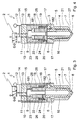
- FIGS. 1 to 4 show an injection valve 1, the component of a so-called common rail injection system is and to the injection of fuel in a combustion chamber of a diesel internal combustion engine one Motor vehicle serves.
- the injection valve 1 comprises for this purpose as essential building units a here only in principle represented, Valve-shaped valve control module 2 and a nozzle module 3.
- the nozzle module 3 is designed as a coaxial Vario nozzle and has for this purpose a needle unit, which consists of an outer Nozzle needle 4 and an inner, the outer nozzle needle. 4 sweeping nozzle needle 5 is formed.
- the outer nozzle needle 4, the axially displaceable in one Valve housing 6 is guided, is used to control the first, leading to the combustion chamber of the diesel internal combustion engine Injection openings or nozzles 7, and the inner nozzle needle 5 is used to control the second, also to the Combustion chamber of the diesel engine leading injection ports or nozzles 8.
- a valve control chamber 9 is formed, on the one hand via a with an inlet throttle 10 formed inlet channel 11 with a fuel supply line 12 and on the other hand via one with an outlet throttle 13 provided drain channel 14 with the valve-like trained valve control module 2 is connected.
- the inlet throttle 10 and the outlet throttle 13 are in a valve plate 15 formed, the valve control chamber 9 frontally limited.
- the outer nozzle needle 4 is radially of an annular trained high-pressure chamber 16 surrounded, in which a Fuel supply channel 17 opens, via the fuel supply line 12 with a so-called common rail of the injection system is connected by means of several injectors the type shown are supplied.
- the pressure room 16 can under a usual in common rail systems High pressure of, for example, up to 1.6 kbar stand.
- the outer Nozzle needle 4 In the upper region of the high-pressure chamber 16, the outer Nozzle needle 4, a pressure shoulder 17, on which a Opening the outer nozzle needle 4 supporting fluid pressure acts.
- the outer nozzle needle 4 is further a control piston 18 associated with the injection nozzles 8 facing away from it Front side adjacent to the valve control chamber 9 and the by means of a coil spring 19, which on the one hand on the Housing 6 supported and on the other hand on a collar 20th the control piston 18 acts in the closing direction of the outer Pre-stressed nozzle needle 4.
- the inner nozzle needle 5 is in an outer nozzle needle 4 axially extending channel 21 and includes a Pressure pin 22, which passes through the control piston 18 axially and is guided in this.
- the pressure pin 22 has a lower Diameter as the area of the inner nozzle needle 5, which is guided in the outer nozzle needle 4, and has a mushroom-shaped end portion 23 which in the control room 9 sticks out.
- the pressure pin 22 is located in that shown in FIG Loose position on the in the outer nozzle needle 4th guided area of the inner nozzle needle 5 at.
- the inner nozzle needle 5 further downstream of her associated injectors 8 a pressure stage 27, on the with open nozzle needle 4, an opening of the inner nozzle needle 5 supporting fluid pressure acts.
- the valve control module 2 is formed like a valve and has two switch positions. In a shown in Figures 1 and 4 Switching position, the outlet throttle 13 is locked and in the other switching position shown in Figures 2 and 3, the outlet throttle 13 is released, so that fuel can flow out of the valve control chamber 9, which leads to a pressure relief of the same.
- valve control module 2 in the present case a piezoelectric actuator, not shown on, which acts on a valve closure member, the one Fluid flow between the control chamber 9 of the nozzle module 3 and a return line of the valve control module 2 releases or locks.
- the injection valve 1 shown in Figures 1 to 4 works in the manner described below.
- FIG. 1 the closed position of the two nozzle needles 4 and FIG. 5, in which via the injection nozzles 7 and 8 no fuel enters the combustion chamber of the internal combustion engine.
- the valve control module 2 is in its blocking position, so that over the outlet throttle 13 no fuel can flow out of the control room 9.
- the in the control chamber 9 prevailing fuel pressure on the inlet throttle 10, which has a smaller diameter than the Outflow throttle 13 has provided the so-called rail pressure
- the outer nozzle needle 4 and the inner nozzle needle 5 via the valve spool 18 in the closed position holds, in the closed position on the two nozzle needles. 4 and 5 facing away from the injection nozzles 7 and 8, respectively Front side attacks.
- the pressure pin 22 is characterized by in the Control room prevailing fluid pressure against that in the outer Nozzle needle guided area of the inner nozzle needle 5 is pressed.
- valve-like design Valve control module 2 is actuated, takes place Pressure relief of the control chamber 9, causing the valve spool 18 an axial offset in the injection nozzles 7 and 8 opposite direction undergoes.
- the valve spool 18 By the at the Pressure shoulder 17 attacking fluid pressure follows the outer Nozzle needle 4 the valve spool 18, so that the outer Nozzle needle 4 associated injectors 7 released be and fuel into the combustion chamber of the internal combustion engine is injected.
- the valve control piston 18 is used when opening via a driving edge 181 as a driver for the pressure pin 22 of the inner Nozzle needle 5, so that control room side no force more on the inner nozzle needle 5 acts and the latter by acting on the front side formed pressure stage 27 Fluid pressure opens.
- the valve control piston 18 is continue to proceed to an upper stop 28, and the Push pin 22, when the control of the valve control module not terminated beforehand, by means of the over the Pressure stage 27 on the inner nozzle needle 5 acting fluid pressure proceed as far as the end-side end area 23 rests against the valve plate 15.
- the pressure pin 22 or whose end portion 23 is located on the valve plate 15th indicate that fuel is flowing through the outflow throttle 13 can. This valve position is shown in FIG.
- the control piston 18 engages in his Function as a driver via a driver edge 182 also on the injection nozzles 8 facing away from the front in the outer nozzle needle 4 guided portion of the inner nozzle needle 5, so that the inner nozzle needle 5 in the locked position is brought and the associated injectors 8 closes.
- the inner nozzle needle 5 and the outer nozzle needle 4 are thus substantially simultaneously placed in the closed position, as Figure 4 can be seen.
- the pressure pin 22 lifts when closing the nozzle needles 4 and 5 of the guided in the outer nozzle needle 4 area the inner nozzle needle 5 from. He only learns after the Closing the injectors 7 and 8 an offset in its starting position shown in Figure 1, wherein the eventual Pressure reduction in the space between the pressure pin 22 and that of the guided in the outer nozzle needle Area of the inner nozzle needle 5 a not closer illustrated discharge channel can be provided.
Landscapes
- Engineering & Computer Science (AREA)
- Chemical & Material Sciences (AREA)
- Combustion & Propulsion (AREA)
- Mechanical Engineering (AREA)
- General Engineering & Computer Science (AREA)
- Physics & Mathematics (AREA)
- Fluid Mechanics (AREA)
- Fuel-Injection Apparatus (AREA)
Abstract
Description
Claims (7)
- Einspritzventil, mit einem Düsenmodul (3), in dem eine erste, mit mindestens einer ersten Einspritzöffnung (7) zusammenwirkende Düsennadel (4) und eine zweite, mit mindestens einer zweiten Einspritzöffnung (8) zusammenwirkende, in einem die erste Düsennadel (4) axial durchgreifenden Kanal (21) geführte Düsennadel (5) axial verschieblich geführt sind, und mit einem Ventilsteuermodul (2), das einen Fluiddruck steuert, der in einem Ventilsteuerraum (9) herrscht und dessen Niveau die Lage der ersten Düsennadel (4) und der zweiten Düsennadel (5) festlegt, dadurch gekennzeichnet, dass der ersten Düsennadel (4) mindestens ein Mitnehmer (18) zugeordnet ist, der ein Öffnen und ein Schließen der zweiten Düsennadel (5) bewirkt.
- Einspritzventil nach Anspruch 1, dadurch gekennzeichnet, dass der Mitnehmer (18) von einem Steuerkolben der ersten Düsennadel (4) gebildet ist, der vorzugsweise einen Bereich verringerten Durchmessers der zweiten Düsennadel (5) umschließt.
- Einspritzventil nach Anspruch 2, dadurch gekennzeichnet, dass in dem Steuerkolben (18) ein Druckstift (22) der zweiten Düsennadel (5) geführt ist.
- Einspritzventil nach Anspruch 3, dadurch gekennzeichnet, dass der Druckstift (22) einstückiger Bestandteil der zweiten Düsennadel ist.
- Einspritzventil nach Anspruch 3 oder 4, dadurch gekennzeichnet, dass der Druckstift (22) einen pilzförmigen Endbereich (23) hat, an dem der Mitnehmer (18) beim Öffnen der ersten Düsennadel (4) angreift.
- Einspritzventil nach einem der Ansprüche 3 bis 5, dadurch gekennzeichnet, dass der Druckstift (22) mit einer als Anschlag dienenden Ventilplatte (15) zusammenwirkt, in der eine Zulaufdrossel (10) und eine Ablaufdrossel (13) zur Steuerung des Fluiddrucks in dem Ventilsteuerraum (9) angeordnet sind.
- Einspritzventil nach Anspruch 2, dadurch gekennzeichnet, dass der Steuerkolben (18) mit seiner dem Ventilsteuerraum (9) abgewandten Stirnseite mit der ersten Düsennadel (4) und der zweiten Düsennadel (5) zusammenwirkt.
Applications Claiming Priority (2)
| Application Number | Priority Date | Filing Date | Title |
|---|---|---|---|
| DE10357873 | 2003-12-11 | ||
| DE2003157873 DE10357873A1 (de) | 2003-12-11 | 2003-12-11 | Einspritzventil |
Publications (2)
| Publication Number | Publication Date |
|---|---|
| EP1541859A1 true EP1541859A1 (de) | 2005-06-15 |
| EP1541859B1 EP1541859B1 (de) | 2009-07-22 |
Family
ID=34485303
Family Applications (1)
| Application Number | Title | Priority Date | Filing Date |
|---|---|---|---|
| EP20040024922 Expired - Lifetime EP1541859B1 (de) | 2003-12-11 | 2004-10-20 | Einspritzventil |
Country Status (2)
| Country | Link |
|---|---|
| EP (1) | EP1541859B1 (de) |
| DE (2) | DE10357873A1 (de) |
Cited By (4)
| Publication number | Priority date | Publication date | Assignee | Title |
|---|---|---|---|---|
| DE102006035412B4 (de) * | 2005-11-09 | 2008-08-28 | Denso Corp., Kariya | Kraftstoffeinspritzvorrichtung |
| DE102007000095B4 (de) * | 2006-02-16 | 2009-04-16 | Denso Corp., Kariya-shi | Kraftstoffeinspritzelement |
| DE102007000037B4 (de) * | 2006-01-26 | 2010-09-02 | Toyota Jidosha Kabushiki Kaisha, Toyota-shi | Kraftstoffeinspritzsystem |
| US10454103B2 (en) | 2013-03-14 | 2019-10-22 | Group14 Technologies, Inc. | Composite carbon materials comprising lithium alloying electrochemical modifiers |
Families Citing this family (3)
| Publication number | Priority date | Publication date | Assignee | Title |
|---|---|---|---|---|
| JP4475250B2 (ja) * | 2005-06-06 | 2010-06-09 | 株式会社デンソー | 燃料噴射弁およびその製造方法 |
| DE102012002542A1 (de) | 2012-02-09 | 2013-08-14 | Volkswagen Aktiengesellschaft | Verfahren zum Einspritzen von Kraftstoff in einen Brennraum eines Zylinders |
| DE102013000048B3 (de) * | 2013-01-07 | 2014-06-12 | L'orange Gmbh | Doppelnadelinjektor |
Citations (5)
| Publication number | Priority date | Publication date | Assignee | Title |
|---|---|---|---|---|
| DE3332920A1 (de) * | 1983-09-13 | 1985-03-21 | Klöckner-Humboldt-Deutz AG, 5000 Köln | Kraftstoffeinspritzduese |
| DE4115477A1 (de) * | 1990-05-17 | 1991-11-21 | Avl Verbrennungskraft Messtech | Einspritzduese fuer eine brennkraftmaschine |
| DE10038054A1 (de) * | 1999-08-05 | 2001-02-15 | Avl List Gmbh | Nockenbetätigte Einspritzeinrichtung für eine Brennkraftmaschine |
| DE10133434A1 (de) * | 2001-07-10 | 2003-01-23 | Bosch Gmbh Robert | Kraftstoffeinspritzventil für Brennkraftmaschinen |
| DE10205970A1 (de) * | 2002-02-14 | 2003-09-04 | Bosch Gmbh Robert | Kraftstoffeinspritzventil für Brennkraftmaschinen |
-
2003
- 2003-12-11 DE DE2003157873 patent/DE10357873A1/de not_active Withdrawn
-
2004
- 2004-10-20 DE DE200450009781 patent/DE502004009781D1/de not_active Expired - Lifetime
- 2004-10-20 EP EP20040024922 patent/EP1541859B1/de not_active Expired - Lifetime
Patent Citations (5)
| Publication number | Priority date | Publication date | Assignee | Title |
|---|---|---|---|---|
| DE3332920A1 (de) * | 1983-09-13 | 1985-03-21 | Klöckner-Humboldt-Deutz AG, 5000 Köln | Kraftstoffeinspritzduese |
| DE4115477A1 (de) * | 1990-05-17 | 1991-11-21 | Avl Verbrennungskraft Messtech | Einspritzduese fuer eine brennkraftmaschine |
| DE10038054A1 (de) * | 1999-08-05 | 2001-02-15 | Avl List Gmbh | Nockenbetätigte Einspritzeinrichtung für eine Brennkraftmaschine |
| DE10133434A1 (de) * | 2001-07-10 | 2003-01-23 | Bosch Gmbh Robert | Kraftstoffeinspritzventil für Brennkraftmaschinen |
| DE10205970A1 (de) * | 2002-02-14 | 2003-09-04 | Bosch Gmbh Robert | Kraftstoffeinspritzventil für Brennkraftmaschinen |
Cited By (4)
| Publication number | Priority date | Publication date | Assignee | Title |
|---|---|---|---|---|
| DE102006035412B4 (de) * | 2005-11-09 | 2008-08-28 | Denso Corp., Kariya | Kraftstoffeinspritzvorrichtung |
| DE102007000037B4 (de) * | 2006-01-26 | 2010-09-02 | Toyota Jidosha Kabushiki Kaisha, Toyota-shi | Kraftstoffeinspritzsystem |
| DE102007000095B4 (de) * | 2006-02-16 | 2009-04-16 | Denso Corp., Kariya-shi | Kraftstoffeinspritzelement |
| US10454103B2 (en) | 2013-03-14 | 2019-10-22 | Group14 Technologies, Inc. | Composite carbon materials comprising lithium alloying electrochemical modifiers |
Also Published As
| Publication number | Publication date |
|---|---|
| DE10357873A1 (de) | 2005-07-07 |
| DE502004009781D1 (de) | 2009-09-03 |
| EP1541859B1 (de) | 2009-07-22 |
Similar Documents
| Publication | Publication Date | Title |
|---|---|---|
| EP1478840B1 (de) | Kraftstoffeinspritzventil für brennkraftmaschinen | |
| DE102007042466B3 (de) | Einspritzsystem mit reduzierter Schaltleckage und Verfahren zum Herstellen eines Einspritzsystems | |
| DE10100390A1 (de) | Einspritzventil | |
| EP1541859B1 (de) | Einspritzventil | |
| EP1925812B1 (de) | Kraftstoffeinspritzventil für Brennkraftmaschinen | |
| EP1144842B1 (de) | Injektor für ein kraftstoffeinspritzsystem für brennkraftmaschinen mit in den ventilsteuerraum ragender düsennadel | |
| EP1939441A2 (de) | Kraftstoffinjektor | |
| EP1952011B1 (de) | Kraftstoff-einspritzvorrichtung für eine brennkraftmaschine mit kraftstoff-direkteinspritzung | |
| AT501914A4 (de) | Vorrichtung zum einspritzen von kraftstoff in den brennraum einer brennkraftmaschine | |
| EP1961949B1 (de) | Injektor mit zusätzlichem Servoventil | |
| EP2022975B1 (de) | Injektor | |
| DE102007010498A1 (de) | Injektor zum Einspritzen von Kraftstoff in einen Brennraum einer Brennkraftmaschine | |
| EP1362179A1 (de) | Einspritzventil | |
| DE102007005382A1 (de) | Leckagefreier Injektor | |
| DE10320980A1 (de) | Verfahren zur Mehrfachansteuerung eines Kraftstoffinjektors mit Variodüse | |
| DE102004015746A1 (de) | Kraftstoffeinspritzventil | |
| DE102010042251A1 (de) | Kraftstoffinjektor für eine Brennkraftmaschine | |
| EP2204570B1 (de) | Kraftstoff-Injektor | |
| DE102005032464A1 (de) | Kraftstoffinjektor mit Vorsteuerraum | |
| DE102004011095A1 (de) | Kraftstoffeinspritzventil | |
| DE102019215119A1 (de) | Kraftstoffinjektor | |
| EP1719904A1 (de) | Kraftstoffeinspritzdüse | |
| DE102007001365A1 (de) | Injektor mit Steuer- und Schaltkammer | |
| EP2019198A2 (de) | Injektor | |
| DE10032924A1 (de) | Kraftstoffeinspritzvorrichtung für Brennkraftmaschinen |
Legal Events
| Date | Code | Title | Description |
|---|---|---|---|
| PUAI | Public reference made under article 153(3) epc to a published international application that has entered the european phase |
Free format text: ORIGINAL CODE: 0009012 |
|
| AK | Designated contracting states |
Kind code of ref document: A1 Designated state(s): AT BE BG CH CY CZ DE DK EE ES FI FR GB GR HU IE IT LI LU MC NL PL PT RO SE SI SK TR |
|
| AX | Request for extension of the european patent |
Extension state: AL HR LT LV MK |
|
| 17P | Request for examination filed |
Effective date: 20051215 |
|
| AKX | Designation fees paid |
Designated state(s): DE ES FR IT PL |
|
| 17Q | First examination report despatched |
Effective date: 20070824 |
|
| GRAP | Despatch of communication of intention to grant a patent |
Free format text: ORIGINAL CODE: EPIDOSNIGR1 |
|
| GRAS | Grant fee paid |
Free format text: ORIGINAL CODE: EPIDOSNIGR3 |
|
| GRAA | (expected) grant |
Free format text: ORIGINAL CODE: 0009210 |
|
| AK | Designated contracting states |
Kind code of ref document: B1 Designated state(s): DE ES FR IT PL |
|
| REF | Corresponds to: |
Ref document number: 502004009781 Country of ref document: DE Date of ref document: 20090903 Kind code of ref document: P |
|
| PG25 | Lapsed in a contracting state [announced via postgrant information from national office to epo] |
Ref country code: ES Free format text: LAPSE BECAUSE OF FAILURE TO SUBMIT A TRANSLATION OF THE DESCRIPTION OR TO PAY THE FEE WITHIN THE PRESCRIBED TIME-LIMIT Effective date: 20091102 |
|
| PG25 | Lapsed in a contracting state [announced via postgrant information from national office to epo] |
Ref country code: PL Free format text: LAPSE BECAUSE OF FAILURE TO SUBMIT A TRANSLATION OF THE DESCRIPTION OR TO PAY THE FEE WITHIN THE PRESCRIBED TIME-LIMIT Effective date: 20090722 |
|
| PLBE | No opposition filed within time limit |
Free format text: ORIGINAL CODE: 0009261 |
|
| STAA | Information on the status of an ep patent application or granted ep patent |
Free format text: STATUS: NO OPPOSITION FILED WITHIN TIME LIMIT |
|
| 26N | No opposition filed |
Effective date: 20100423 |
|
| PG25 | Lapsed in a contracting state [announced via postgrant information from national office to epo] |
Ref country code: IT Free format text: LAPSE BECAUSE OF FAILURE TO SUBMIT A TRANSLATION OF THE DESCRIPTION OR TO PAY THE FEE WITHIN THE PRESCRIBED TIME-LIMIT Effective date: 20090722 |
|
| REG | Reference to a national code |
Ref country code: FR Ref legal event code: PLFP Year of fee payment: 12 |
|
| REG | Reference to a national code |
Ref country code: FR Ref legal event code: PLFP Year of fee payment: 13 |
|
| REG | Reference to a national code |
Ref country code: FR Ref legal event code: PLFP Year of fee payment: 14 |
|
| PGFP | Annual fee paid to national office [announced via postgrant information from national office to epo] |
Ref country code: FR Payment date: 20171023 Year of fee payment: 14 |
|
| PGFP | Annual fee paid to national office [announced via postgrant information from national office to epo] |
Ref country code: DE Payment date: 20181206 Year of fee payment: 15 |
|
| PG25 | Lapsed in a contracting state [announced via postgrant information from national office to epo] |
Ref country code: FR Free format text: LAPSE BECAUSE OF NON-PAYMENT OF DUE FEES Effective date: 20181031 |
|
| REG | Reference to a national code |
Ref country code: DE Ref legal event code: R119 Ref document number: 502004009781 Country of ref document: DE |
|
| PG25 | Lapsed in a contracting state [announced via postgrant information from national office to epo] |
Ref country code: DE Free format text: LAPSE BECAUSE OF NON-PAYMENT OF DUE FEES Effective date: 20200501 |