EP1541808A1 - Turbinenbauteil mit Wärmedämmschicht und Erosionsschutzschicht - Google Patents
Turbinenbauteil mit Wärmedämmschicht und Erosionsschutzschicht Download PDFInfo
- Publication number
- EP1541808A1 EP1541808A1 EP03028576A EP03028576A EP1541808A1 EP 1541808 A1 EP1541808 A1 EP 1541808A1 EP 03028576 A EP03028576 A EP 03028576A EP 03028576 A EP03028576 A EP 03028576A EP 1541808 A1 EP1541808 A1 EP 1541808A1
- Authority
- EP
- European Patent Office
- Prior art keywords
- component according
- thermal barrier
- barrier coating
- component
- nickel
- Prior art date
- Legal status (The legal status is an assumption and is not a legal conclusion. Google has not performed a legal analysis and makes no representation as to the accuracy of the status listed.)
- Withdrawn
Links
- 230000003628 erosive effect Effects 0.000 title claims abstract description 34
- 238000000576 coating method Methods 0.000 title description 4
- 239000011248 coating agent Substances 0.000 title description 2
- 239000012720 thermal barrier coating Substances 0.000 claims description 65
- 239000010410 layer Substances 0.000 claims description 46
- PXHVJJICTQNCMI-UHFFFAOYSA-N Nickel Chemical compound [Ni] PXHVJJICTQNCMI-UHFFFAOYSA-N 0.000 claims description 36
- 239000000758 substrate Substances 0.000 claims description 30
- XEEYBQQBJWHFJM-UHFFFAOYSA-N Iron Chemical compound [Fe] XEEYBQQBJWHFJM-UHFFFAOYSA-N 0.000 claims description 20
- 239000011241 protective layer Substances 0.000 claims description 15
- UFGZSIPAQKLCGR-UHFFFAOYSA-N chromium carbide Chemical compound [Cr]#C[Cr]C#[Cr] UFGZSIPAQKLCGR-UHFFFAOYSA-N 0.000 claims description 14
- 229910052759 nickel Inorganic materials 0.000 claims description 14
- 229910003470 tongbaite Inorganic materials 0.000 claims description 14
- 239000000919 ceramic Substances 0.000 claims description 12
- 239000011651 chromium Substances 0.000 claims description 12
- 239000000463 material Substances 0.000 claims description 10
- 229910052742 iron Inorganic materials 0.000 claims description 9
- VYZAMTAEIAYCRO-UHFFFAOYSA-N Chromium Chemical compound [Cr] VYZAMTAEIAYCRO-UHFFFAOYSA-N 0.000 claims description 7
- XUIMIQQOPSSXEZ-UHFFFAOYSA-N Silicon Chemical compound [Si] XUIMIQQOPSSXEZ-UHFFFAOYSA-N 0.000 claims description 7
- 229910052804 chromium Inorganic materials 0.000 claims description 7
- 229910052710 silicon Inorganic materials 0.000 claims description 7
- 239000010703 silicon Substances 0.000 claims description 7
- VNNRSPGTAMTISX-UHFFFAOYSA-N chromium nickel Chemical compound [Cr].[Ni] VNNRSPGTAMTISX-UHFFFAOYSA-N 0.000 claims description 6
- 229910017052 cobalt Inorganic materials 0.000 claims description 6
- 239000010941 cobalt Substances 0.000 claims description 6
- GUTLYIVDDKVIGB-UHFFFAOYSA-N cobalt atom Chemical compound [Co] GUTLYIVDDKVIGB-UHFFFAOYSA-N 0.000 claims description 6
- 229910018487 Ni—Cr Inorganic materials 0.000 claims description 5
- 229910052782 aluminium Inorganic materials 0.000 claims description 5
- 239000000203 mixture Substances 0.000 claims description 5
- RVTZCBVAJQQJTK-UHFFFAOYSA-N oxygen(2-);zirconium(4+) Chemical compound [O-2].[O-2].[Zr+4] RVTZCBVAJQQJTK-UHFFFAOYSA-N 0.000 claims description 5
- 229910052727 yttrium Inorganic materials 0.000 claims description 5
- VWQVUPCCIRVNHF-UHFFFAOYSA-N yttrium atom Chemical group [Y] VWQVUPCCIRVNHF-UHFFFAOYSA-N 0.000 claims description 5
- 229910001928 zirconium oxide Inorganic materials 0.000 claims description 5
- XAGFODPZIPBFFR-UHFFFAOYSA-N aluminium Chemical compound [Al] XAGFODPZIPBFFR-UHFFFAOYSA-N 0.000 claims description 4
- UONOETXJSWQNOL-UHFFFAOYSA-N tungsten carbide Chemical compound [W+]#[C-] UONOETXJSWQNOL-UHFFFAOYSA-N 0.000 claims description 4
- GWEVSGVZZGPLCZ-UHFFFAOYSA-N Titan oxide Chemical compound O=[Ti]=O GWEVSGVZZGPLCZ-UHFFFAOYSA-N 0.000 claims description 3
- 229910045601 alloy Inorganic materials 0.000 claims description 3
- 239000000956 alloy Substances 0.000 claims description 3
- 229910001120 nichrome Inorganic materials 0.000 claims description 3
- SIWVEOZUMHYXCS-UHFFFAOYSA-N oxo(oxoyttriooxy)yttrium Chemical compound O=[Y]O[Y]=O SIWVEOZUMHYXCS-UHFFFAOYSA-N 0.000 claims description 3
- ZOXJGFHDIHLPTG-UHFFFAOYSA-N Boron Chemical compound [B] ZOXJGFHDIHLPTG-UHFFFAOYSA-N 0.000 claims description 2
- 229910000640 Fe alloy Inorganic materials 0.000 claims description 2
- NPXOKRUENSOPAO-UHFFFAOYSA-N Raney nickel Chemical compound [Al].[Ni] NPXOKRUENSOPAO-UHFFFAOYSA-N 0.000 claims description 2
- 229910052796 boron Inorganic materials 0.000 claims description 2
- 229910000531 Co alloy Inorganic materials 0.000 claims 1
- 229910000599 Cr alloy Inorganic materials 0.000 claims 1
- 229910000990 Ni alloy Inorganic materials 0.000 claims 1
- 230000002035 prolonged effect Effects 0.000 claims 1
- 229910002076 stabilized zirconia Inorganic materials 0.000 claims 1
- 238000009413 insulation Methods 0.000 abstract description 6
- 229910000831 Steel Inorganic materials 0.000 description 7
- 239000010959 steel Substances 0.000 description 7
- 229910052751 metal Inorganic materials 0.000 description 4
- 239000002184 metal Substances 0.000 description 4
- 230000003647 oxidation Effects 0.000 description 4
- 238000007254 oxidation reaction Methods 0.000 description 4
- 230000007797 corrosion Effects 0.000 description 3
- 238000005260 corrosion Methods 0.000 description 3
- 239000012535 impurity Substances 0.000 description 3
- MCMNRKCIXSYSNV-UHFFFAOYSA-N Zirconium dioxide Chemical compound O=[Zr]=O MCMNRKCIXSYSNV-UHFFFAOYSA-N 0.000 description 2
- 238000004519 manufacturing process Methods 0.000 description 2
- 238000007750 plasma spraying Methods 0.000 description 2
- 229910052706 scandium Inorganic materials 0.000 description 2
- SIXSYDAISGFNSX-UHFFFAOYSA-N scandium atom Chemical compound [Sc] SIXSYDAISGFNSX-UHFFFAOYSA-N 0.000 description 2
- 230000035939 shock Effects 0.000 description 2
- 229910000601 superalloy Inorganic materials 0.000 description 2
- OGIDPMRJRNCKJF-UHFFFAOYSA-N titanium oxide Inorganic materials [Ti]=O OGIDPMRJRNCKJF-UHFFFAOYSA-N 0.000 description 2
- 238000010290 vacuum plasma spraying Methods 0.000 description 2
- 238000006424 Flood reaction Methods 0.000 description 1
- 229910000943 NiAl Inorganic materials 0.000 description 1
- 230000004888 barrier function Effects 0.000 description 1
- 238000002485 combustion reaction Methods 0.000 description 1
- 238000009792 diffusion process Methods 0.000 description 1
- 239000012530 fluid Substances 0.000 description 1
- 238000010438 heat treatment Methods 0.000 description 1
- 238000000265 homogenisation Methods 0.000 description 1
- CPLXHLVBOLITMK-UHFFFAOYSA-N magnesium oxide Inorganic materials [Mg]=O CPLXHLVBOLITMK-UHFFFAOYSA-N 0.000 description 1
- 239000000395 magnesium oxide Substances 0.000 description 1
- AXZKOIWUVFPNLO-UHFFFAOYSA-N magnesium;oxygen(2-) Chemical compound [O-2].[Mg+2] AXZKOIWUVFPNLO-UHFFFAOYSA-N 0.000 description 1
- 238000012423 maintenance Methods 0.000 description 1
- 229910001092 metal group alloy Inorganic materials 0.000 description 1
- IKBUJAGPKSFLPB-UHFFFAOYSA-N nickel yttrium Chemical compound [Ni].[Y] IKBUJAGPKSFLPB-UHFFFAOYSA-N 0.000 description 1
- 239000002245 particle Substances 0.000 description 1
- 239000011148 porous material Substances 0.000 description 1
- 238000009419 refurbishment Methods 0.000 description 1
- 238000012958 reprocessing Methods 0.000 description 1
- 239000002356 single layer Substances 0.000 description 1
- 229910000679 solder Inorganic materials 0.000 description 1
- 229910001220 stainless steel Inorganic materials 0.000 description 1
- 238000003860 storage Methods 0.000 description 1
- 239000000126 substance Substances 0.000 description 1
- 230000000930 thermomechanical effect Effects 0.000 description 1
- 230000003313 weakening effect Effects 0.000 description 1
- 238000003466 welding Methods 0.000 description 1
Images




Classifications
-
- C—CHEMISTRY; METALLURGY
- C23—COATING METALLIC MATERIAL; COATING MATERIAL WITH METALLIC MATERIAL; CHEMICAL SURFACE TREATMENT; DIFFUSION TREATMENT OF METALLIC MATERIAL; COATING BY VACUUM EVAPORATION, BY SPUTTERING, BY ION IMPLANTATION OR BY CHEMICAL VAPOUR DEPOSITION, IN GENERAL; INHIBITING CORROSION OF METALLIC MATERIAL OR INCRUSTATION IN GENERAL
- C23C—COATING METALLIC MATERIAL; COATING MATERIAL WITH METALLIC MATERIAL; SURFACE TREATMENT OF METALLIC MATERIAL BY DIFFUSION INTO THE SURFACE, BY CHEMICAL CONVERSION OR SUBSTITUTION; COATING BY VACUUM EVAPORATION, BY SPUTTERING, BY ION IMPLANTATION OR BY CHEMICAL VAPOUR DEPOSITION, IN GENERAL
- C23C28/00—Coating for obtaining at least two superposed coatings either by methods not provided for in a single one of groups C23C2/00 - C23C26/00 or by combinations of methods provided for in subclasses C23C and C25C or C25D
- C23C28/30—Coatings combining at least one metallic layer and at least one inorganic non-metallic layer
- C23C28/32—Coatings combining at least one metallic layer and at least one inorganic non-metallic layer including at least one pure metallic layer
- C23C28/321—Coatings combining at least one metallic layer and at least one inorganic non-metallic layer including at least one pure metallic layer with at least one metal alloy layer
- C23C28/3215—Coatings combining at least one metallic layer and at least one inorganic non-metallic layer including at least one pure metallic layer with at least one metal alloy layer at least one MCrAlX layer
-
- C—CHEMISTRY; METALLURGY
- C23—COATING METALLIC MATERIAL; COATING MATERIAL WITH METALLIC MATERIAL; CHEMICAL SURFACE TREATMENT; DIFFUSION TREATMENT OF METALLIC MATERIAL; COATING BY VACUUM EVAPORATION, BY SPUTTERING, BY ION IMPLANTATION OR BY CHEMICAL VAPOUR DEPOSITION, IN GENERAL; INHIBITING CORROSION OF METALLIC MATERIAL OR INCRUSTATION IN GENERAL
- C23C—COATING METALLIC MATERIAL; COATING MATERIAL WITH METALLIC MATERIAL; SURFACE TREATMENT OF METALLIC MATERIAL BY DIFFUSION INTO THE SURFACE, BY CHEMICAL CONVERSION OR SUBSTITUTION; COATING BY VACUUM EVAPORATION, BY SPUTTERING, BY ION IMPLANTATION OR BY CHEMICAL VAPOUR DEPOSITION, IN GENERAL
- C23C28/00—Coating for obtaining at least two superposed coatings either by methods not provided for in a single one of groups C23C2/00 - C23C26/00 or by combinations of methods provided for in subclasses C23C and C25C or C25D
- C23C28/30—Coatings combining at least one metallic layer and at least one inorganic non-metallic layer
- C23C28/32—Coatings combining at least one metallic layer and at least one inorganic non-metallic layer including at least one pure metallic layer
- C23C28/321—Coatings combining at least one metallic layer and at least one inorganic non-metallic layer including at least one pure metallic layer with at least one metal alloy layer
-
- C—CHEMISTRY; METALLURGY
- C23—COATING METALLIC MATERIAL; COATING MATERIAL WITH METALLIC MATERIAL; CHEMICAL SURFACE TREATMENT; DIFFUSION TREATMENT OF METALLIC MATERIAL; COATING BY VACUUM EVAPORATION, BY SPUTTERING, BY ION IMPLANTATION OR BY CHEMICAL VAPOUR DEPOSITION, IN GENERAL; INHIBITING CORROSION OF METALLIC MATERIAL OR INCRUSTATION IN GENERAL
- C23C—COATING METALLIC MATERIAL; COATING MATERIAL WITH METALLIC MATERIAL; SURFACE TREATMENT OF METALLIC MATERIAL BY DIFFUSION INTO THE SURFACE, BY CHEMICAL CONVERSION OR SUBSTITUTION; COATING BY VACUUM EVAPORATION, BY SPUTTERING, BY ION IMPLANTATION OR BY CHEMICAL VAPOUR DEPOSITION, IN GENERAL
- C23C28/00—Coating for obtaining at least two superposed coatings either by methods not provided for in a single one of groups C23C2/00 - C23C26/00 or by combinations of methods provided for in subclasses C23C and C25C or C25D
- C23C28/30—Coatings combining at least one metallic layer and at least one inorganic non-metallic layer
- C23C28/32—Coatings combining at least one metallic layer and at least one inorganic non-metallic layer including at least one pure metallic layer
- C23C28/324—Coatings combining at least one metallic layer and at least one inorganic non-metallic layer including at least one pure metallic layer with at least one metal matrix material layer comprising a mixture of at least two metals or metal phases or a metal-matrix material with hard embedded particles, e.g. WC-Me
-
- C—CHEMISTRY; METALLURGY
- C23—COATING METALLIC MATERIAL; COATING MATERIAL WITH METALLIC MATERIAL; CHEMICAL SURFACE TREATMENT; DIFFUSION TREATMENT OF METALLIC MATERIAL; COATING BY VACUUM EVAPORATION, BY SPUTTERING, BY ION IMPLANTATION OR BY CHEMICAL VAPOUR DEPOSITION, IN GENERAL; INHIBITING CORROSION OF METALLIC MATERIAL OR INCRUSTATION IN GENERAL
- C23C—COATING METALLIC MATERIAL; COATING MATERIAL WITH METALLIC MATERIAL; SURFACE TREATMENT OF METALLIC MATERIAL BY DIFFUSION INTO THE SURFACE, BY CHEMICAL CONVERSION OR SUBSTITUTION; COATING BY VACUUM EVAPORATION, BY SPUTTERING, BY ION IMPLANTATION OR BY CHEMICAL VAPOUR DEPOSITION, IN GENERAL
- C23C28/00—Coating for obtaining at least two superposed coatings either by methods not provided for in a single one of groups C23C2/00 - C23C26/00 or by combinations of methods provided for in subclasses C23C and C25C or C25D
- C23C28/30—Coatings combining at least one metallic layer and at least one inorganic non-metallic layer
- C23C28/34—Coatings combining at least one metallic layer and at least one inorganic non-metallic layer including at least one inorganic non-metallic material layer, e.g. metal carbide, nitride, boride, silicide layer and their mixtures, enamels, phosphates and sulphates
- C23C28/345—Coatings combining at least one metallic layer and at least one inorganic non-metallic layer including at least one inorganic non-metallic material layer, e.g. metal carbide, nitride, boride, silicide layer and their mixtures, enamels, phosphates and sulphates with at least one oxide layer
-
- C—CHEMISTRY; METALLURGY
- C23—COATING METALLIC MATERIAL; COATING MATERIAL WITH METALLIC MATERIAL; CHEMICAL SURFACE TREATMENT; DIFFUSION TREATMENT OF METALLIC MATERIAL; COATING BY VACUUM EVAPORATION, BY SPUTTERING, BY ION IMPLANTATION OR BY CHEMICAL VAPOUR DEPOSITION, IN GENERAL; INHIBITING CORROSION OF METALLIC MATERIAL OR INCRUSTATION IN GENERAL
- C23C—COATING METALLIC MATERIAL; COATING MATERIAL WITH METALLIC MATERIAL; SURFACE TREATMENT OF METALLIC MATERIAL BY DIFFUSION INTO THE SURFACE, BY CHEMICAL CONVERSION OR SUBSTITUTION; COATING BY VACUUM EVAPORATION, BY SPUTTERING, BY ION IMPLANTATION OR BY CHEMICAL VAPOUR DEPOSITION, IN GENERAL
- C23C28/00—Coating for obtaining at least two superposed coatings either by methods not provided for in a single one of groups C23C2/00 - C23C26/00 or by combinations of methods provided for in subclasses C23C and C25C or C25D
- C23C28/30—Coatings combining at least one metallic layer and at least one inorganic non-metallic layer
- C23C28/34—Coatings combining at least one metallic layer and at least one inorganic non-metallic layer including at least one inorganic non-metallic material layer, e.g. metal carbide, nitride, boride, silicide layer and their mixtures, enamels, phosphates and sulphates
- C23C28/345—Coatings combining at least one metallic layer and at least one inorganic non-metallic layer including at least one inorganic non-metallic material layer, e.g. metal carbide, nitride, boride, silicide layer and their mixtures, enamels, phosphates and sulphates with at least one oxide layer
- C23C28/3455—Coatings combining at least one metallic layer and at least one inorganic non-metallic layer including at least one inorganic non-metallic material layer, e.g. metal carbide, nitride, boride, silicide layer and their mixtures, enamels, phosphates and sulphates with at least one oxide layer with a refractory ceramic layer, e.g. refractory metal oxide, ZrO2, rare earth oxides or a thermal barrier system comprising at least one refractory oxide layer
-
- C—CHEMISTRY; METALLURGY
- C23—COATING METALLIC MATERIAL; COATING MATERIAL WITH METALLIC MATERIAL; CHEMICAL SURFACE TREATMENT; DIFFUSION TREATMENT OF METALLIC MATERIAL; COATING BY VACUUM EVAPORATION, BY SPUTTERING, BY ION IMPLANTATION OR BY CHEMICAL VAPOUR DEPOSITION, IN GENERAL; INHIBITING CORROSION OF METALLIC MATERIAL OR INCRUSTATION IN GENERAL
- C23C—COATING METALLIC MATERIAL; COATING MATERIAL WITH METALLIC MATERIAL; SURFACE TREATMENT OF METALLIC MATERIAL BY DIFFUSION INTO THE SURFACE, BY CHEMICAL CONVERSION OR SUBSTITUTION; COATING BY VACUUM EVAPORATION, BY SPUTTERING, BY ION IMPLANTATION OR BY CHEMICAL VAPOUR DEPOSITION, IN GENERAL
- C23C28/00—Coating for obtaining at least two superposed coatings either by methods not provided for in a single one of groups C23C2/00 - C23C26/00 or by combinations of methods provided for in subclasses C23C and C25C or C25D
- C23C28/30—Coatings combining at least one metallic layer and at least one inorganic non-metallic layer
- C23C28/34—Coatings combining at least one metallic layer and at least one inorganic non-metallic layer including at least one inorganic non-metallic material layer, e.g. metal carbide, nitride, boride, silicide layer and their mixtures, enamels, phosphates and sulphates
- C23C28/347—Coatings combining at least one metallic layer and at least one inorganic non-metallic layer including at least one inorganic non-metallic material layer, e.g. metal carbide, nitride, boride, silicide layer and their mixtures, enamels, phosphates and sulphates with layers adapted for cutting tools or wear applications
-
- C—CHEMISTRY; METALLURGY
- C23—COATING METALLIC MATERIAL; COATING MATERIAL WITH METALLIC MATERIAL; CHEMICAL SURFACE TREATMENT; DIFFUSION TREATMENT OF METALLIC MATERIAL; COATING BY VACUUM EVAPORATION, BY SPUTTERING, BY ION IMPLANTATION OR BY CHEMICAL VAPOUR DEPOSITION, IN GENERAL; INHIBITING CORROSION OF METALLIC MATERIAL OR INCRUSTATION IN GENERAL
- C23C—COATING METALLIC MATERIAL; COATING MATERIAL WITH METALLIC MATERIAL; SURFACE TREATMENT OF METALLIC MATERIAL BY DIFFUSION INTO THE SURFACE, BY CHEMICAL CONVERSION OR SUBSTITUTION; COATING BY VACUUM EVAPORATION, BY SPUTTERING, BY ION IMPLANTATION OR BY CHEMICAL VAPOUR DEPOSITION, IN GENERAL
- C23C28/00—Coating for obtaining at least two superposed coatings either by methods not provided for in a single one of groups C23C2/00 - C23C26/00 or by combinations of methods provided for in subclasses C23C and C25C or C25D
- C23C28/30—Coatings combining at least one metallic layer and at least one inorganic non-metallic layer
- C23C28/36—Coatings combining at least one metallic layer and at least one inorganic non-metallic layer including layers graded in composition or physical properties
-
- C—CHEMISTRY; METALLURGY
- C23—COATING METALLIC MATERIAL; COATING MATERIAL WITH METALLIC MATERIAL; CHEMICAL SURFACE TREATMENT; DIFFUSION TREATMENT OF METALLIC MATERIAL; COATING BY VACUUM EVAPORATION, BY SPUTTERING, BY ION IMPLANTATION OR BY CHEMICAL VAPOUR DEPOSITION, IN GENERAL; INHIBITING CORROSION OF METALLIC MATERIAL OR INCRUSTATION IN GENERAL
- C23C—COATING METALLIC MATERIAL; COATING MATERIAL WITH METALLIC MATERIAL; SURFACE TREATMENT OF METALLIC MATERIAL BY DIFFUSION INTO THE SURFACE, BY CHEMICAL CONVERSION OR SUBSTITUTION; COATING BY VACUUM EVAPORATION, BY SPUTTERING, BY ION IMPLANTATION OR BY CHEMICAL VAPOUR DEPOSITION, IN GENERAL
- C23C30/00—Coating with metallic material characterised only by the composition of the metallic material, i.e. not characterised by the coating process
-
- F—MECHANICAL ENGINEERING; LIGHTING; HEATING; WEAPONS; BLASTING
- F01—MACHINES OR ENGINES IN GENERAL; ENGINE PLANTS IN GENERAL; STEAM ENGINES
- F01D—NON-POSITIVE DISPLACEMENT MACHINES OR ENGINES, e.g. STEAM TURBINES
- F01D25/00—Component parts, details, or accessories, not provided for in, or of interest apart from, other groups
- F01D25/08—Cooling; Heating; Heat-insulation
-
- F—MECHANICAL ENGINEERING; LIGHTING; HEATING; WEAPONS; BLASTING
- F01—MACHINES OR ENGINES IN GENERAL; ENGINE PLANTS IN GENERAL; STEAM ENGINES
- F01D—NON-POSITIVE DISPLACEMENT MACHINES OR ENGINES, e.g. STEAM TURBINES
- F01D5/00—Blades; Blade-carrying members; Heating, heat-insulating, cooling or antivibration means on the blades or the members
- F01D5/12—Blades
- F01D5/28—Selecting particular materials; Particular measures relating thereto; Measures against erosion or corrosion
- F01D5/288—Protective coatings for blades
-
- F—MECHANICAL ENGINEERING; LIGHTING; HEATING; WEAPONS; BLASTING
- F05—INDEXING SCHEMES RELATING TO ENGINES OR PUMPS IN VARIOUS SUBCLASSES OF CLASSES F01-F04
- F05D—INDEXING SCHEME FOR ASPECTS RELATING TO NON-POSITIVE-DISPLACEMENT MACHINES OR ENGINES, GAS-TURBINES OR JET-PROPULSION PLANTS
- F05D2220/00—Application
- F05D2220/30—Application in turbines
- F05D2220/31—Application in turbines in steam turbines
-
- Y—GENERAL TAGGING OF NEW TECHNOLOGICAL DEVELOPMENTS; GENERAL TAGGING OF CROSS-SECTIONAL TECHNOLOGIES SPANNING OVER SEVERAL SECTIONS OF THE IPC; TECHNICAL SUBJECTS COVERED BY FORMER USPC CROSS-REFERENCE ART COLLECTIONS [XRACs] AND DIGESTS
- Y10—TECHNICAL SUBJECTS COVERED BY FORMER USPC
- Y10T—TECHNICAL SUBJECTS COVERED BY FORMER US CLASSIFICATION
- Y10T428/00—Stock material or miscellaneous articles
- Y10T428/12—All metal or with adjacent metals
- Y10T428/12493—Composite; i.e., plural, adjacent, spatially distinct metal components [e.g., layers, joint, etc.]
- Y10T428/12535—Composite; i.e., plural, adjacent, spatially distinct metal components [e.g., layers, joint, etc.] with additional, spatially distinct nonmetal component
- Y10T428/12611—Oxide-containing component
Definitions
- the invention relates to a component with a thermal barrier coating and an erosion control layer according to claim 1.
- Thermal barrier coatings applied to components are known in the field of gas turbines, as e.g. in EP 1 029 115 are described.
- Thermal barrier coatings allow components to be used at higher temperatures than the base material allows, or to extend service life.
- Known base materials (substrates) for gas turbines allow operating temperatures of a maximum of 1000 ° C to 1100 ° C, whereas a coating with a thermal barrier coating allows operating temperatures of up to 1350 ° C.
- a metallic erosion control layer is of particular advantage because it is elastically and plastically deformable due to its ductility.
- the thermal barrier coating does not necessarily serve only the Purpose the range of service temperatures upwards but the thermal expansion due to the Temperature differences that are generated on the component or rest, is evened out in an advantageous manner and / or reduced. So can thermomechanical stresses be avoided or at least reduced.
- FIG. 1 shows a first exemplary embodiment of a component 1 designed according to the invention.
- the component 1 is a component of a gas or steam turbine 300, 303 (FIG. 8), in particular a steam inflow region 333, a turbine blade 342, 354, 357 (FIG. 8) or a housing part 334, 335, 366 (FIG. 8) , 9) and consists of a substrate 4 (supporting structure) and a thermal insulation layer applied thereto 7 and an outer erosion protection layer 13.
- the erosion protection layer 13 can also act simultaneously as a thermal barrier coating, so that then physically only a single layer on the substrate 4 would be present.
- the erosion protection layer 13 is preferably made of a metal or a metal alloy and protects the component from erosion and / or wear, as is the case in particular with steam turbines 300, 303 (FIG. 8) subject to scaling, and at the mean flow velocities from about 50m / s (ie 20m / s - 100m / s) and pressures of 350 to 400 bar.
- the erosion protection layer 13 of a component 1 of a steam turbine 300, 303 may also consist of other materials (eg ceramic).
- the substrate 4 is for example a steel or a other iron-based alloy (for example 1% CrMoV or 10 - 12% chromium steels or IN617) or a nickel or cobalt-based superalloy.
- a steel or a other iron-based alloy for example 1% CrMoV or 10 - 12% chromium steels or IN617) or a nickel or cobalt-based superalloy.
- the heat-insulating layer 7 is in particular a ceramic layer, which consists for example at least partially of zirconium oxide (partially stabilized or fully stabilized by yttrium oxide and / or magnesium oxide) and / or at least partially of titanium oxide and is for example thicker than 0.1 mm.
- thermal barrier coatings 7 consisting of 100% of either zirconia or titanium oxide can be used.
- the ceramic layer 7 can by means of known Coating methods such as atmospheric plasma spraying (APS), vacuum plasma spraying (VPS), low pressure plasma spraying (LPPS) as well as by chemical or physical coating methods be applied (CVD, PVD).
- Coating methods such as atmospheric plasma spraying (APS), vacuum plasma spraying (VPS), low pressure plasma spraying (LPPS) as well as by chemical or physical coating methods be applied (CVD, PVD).
- FIG. 2 shows a further embodiment of the component 1 designed according to the invention.
- the intermediate protective layer 10 serves to protect against corrosion and / or oxidation of the substrate 4 and / or for better bonding of the thermal barrier coating 7 to the substrate 4. This is the case in particular if the thermal barrier coating 7 consists of ceramic and the substrate 4 consists of a metal.
- the intermediate protective layer 10 for protecting a substrate 4 against corrosion and oxidation at a high temperature has, for example, essentially the following elements (indication of the percentages by weight): 11.5 to 20.0 wt% chromium, 0.3 to 1.5 wt% silicon, 0.0 to 1.0 wt% aluminum, 0.0 to 0.7% by weight of yttrium and / or at least one equivalent metal from the group comprising scandium and the elements of the rare earths, Remainder iron, cobalt and / or nickel as well as production-related impurities.
- the metallic intermediate protective layer 10 is made 12.5 to 14.0 wt% Chrome, 0.5 to 1.0 wt% Silicon, 0.1 to 0.5 wt% Aluminum, 0.0 to 0.7 wt% Yttrium and / or at least an equivalent Metal from the group comprising Scandium and the elements of the rare earths, Remainder iron and / or cobalt and / or nickel as well as production-related impurities.
- the composition of the iron-based intermediate protective layer 10 exhibits particularly good properties, so that the intermediate protective layer 10 is outstandingly suitable for application to ferritic substrates 4.
- the coefficients of thermal expansion of substrate 4 and intermediate protective layer 10 can be matched to each other very well (up to 10% difference) or even equal, so that there is no thermally induced stress build-up between substrate 4 and intermediate protective layer 10 (thermal mismatch) could cause flaking of the intermediate protective layer 10.
- the substrate 4 is a ferritic Base alloy, a steel or a nickel or cobalt-based superalloy, in particular a 1% CrMoV steel or a 10 to 12 percent chromium steel.
- the thermal barrier coating 7 at least partially a certain open and / or closed porosity.
- the wear / erosion protective layer 13 a higher density than the thermal barrier coating 7 and exists for example, based on iron alloys, Chromium, nickel and / or cobalt or, for example, NiCr 80/20 or NiCrSiB with admixtures of boron (B) and silicon (Si) or NiAl (eg: Ni: 95wt%, Al 5wt%).
- a metallic erosion protection layer 13 used in steam turbines 300, 303, as the Operating temperatures in steam turbines at Steam inlet area 333 maximum at 450 ° C, 550 ° C, 650 ° C or 850 ° C lie. There are for such temperature ranges enough metallic layers that have a sufficiently large necessary erosion protection over the service life of the component 1 while having good oxidation resistance.
- Metallic erosion protection layers 13 in gas turbines a ceramic thermal barrier coating 7 within the first Stage of the turbine or inside the combustion chamber are not possible because metallic erosion protection layers 13 as outer Do not coat the application temperatures of up to 1350 ° C can withstand.
- a ceramic erosion protection layer 13 exists for example, partially or 100% chromium carbide.
- Other materials for the erosion protection layer 13 are, for example, a mixture of tungsten carbide, chromium carbide and nickel (WC, CrC-Ni), for example, with the weight percentages 73 wt% for tungsten carbide, 20 wt% for chromium carbide and 7 wt% for nickel, also chromium carbide with the Admixing of nickel (Cr 3 C 2 -Ni), for example, with a proportion of 83 wt% chromium carbide and 17 wt% nickel and a mixture of chromium carbide and nickel chromium (Cr 3 C 2 -NiCr), for example, with a share of 75 wt% Chromium carbide and 25 wt% nickel chromium and yttrium-stabilized zirconium oxide, for example, with a weight fraction of 80 wt% zirconium oxide and 20 wt% yttrium oxide.
- WC, CrC-Ni chromium
- the thermal barrier coating 7 is porous, for example.
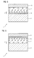
- FIG. 5 shows a porous thermal barrier coating 7 with a gradient of porosity.
- the layer 7 can be used in the region of greater porosity for thermal insulation and, where appropriate, for erosion protection in the area of lower porosity.
- the substrate 4 or one, if necessary existing intermediate protective layer 10 out preferably one greater porosity than in the area of an outer surface or the contact surface with the erosion control layer 13.
- the erosion protection layer 13 preferably has a higher Density than the thermal barrier coating 7, so they 13 a has higher strength.
- FIGS. 7 a, 7 b show the influence of the thermal barrier coating 7 on the thermal deformation behavior of the component. 1
- FIG. 7a shows a component without a thermal barrier coating.
- a higher temperature T max and a lower temperature T min which gives a temperature difference dT (4).
- the temperature difference dT (4) can be at least 200 ° C.
- the higher temperature T max is, for example, at least 450 ° C., in particular even up to 850 ° C.
- the substrate 4 as indicated by dashed lines, expands significantly more in the region of the higher temperature T max due to the thermal expansion than in the region of the lower temperature T min . This differential expansion causes an undesirable deformation of the component (housing).
- a thermal barrier coating 7 is present on the substrate 4, wherein the substrate 4 and the thermal barrier coating 7 together are for example just as thick as the substrate 4 in FIG. 7a.
- the thermal barrier coating 7 reduces the maximum temperature at the surface of the substrate 4 disproportionately to a temperature T ' max , although the external temperature T max is the same as in FIG. 7 a. This results not only from the distance of the surface of the substrate 4 to the higher temperature, but in particular by the lower thermal conductivity of the thermal barrier coating 7.
- the erosion protection layer 13 is here for the sake of simplicity not shown.
- FIG. 8 shows an example of a steam turbine 300, 303 one extending along a rotation axis 306 Turbine shaft 309 shown.
- the steam turbine has a high pressure turbine part 300 and a medium-pressure turbine section 303, each with a Inner housing 312 and a surrounding this outer housing 315 on.
- the high pressure turbine part 300 is, for example, in Pot type executed.
- the medium-pressure turbine section 303 is double-flowed. It is also possible that the Medium-pressure turbine section 303 is designed to be single-entry.
- Along the axis of rotation 306 is between the high pressure turbine part 300 and the medium pressure turbine section 303 a bearing 318th arranged, wherein the turbine shaft 309 in the bearing 318th has a storage area 321.
- the turbine shaft 309 is on another camp 324 next to the high-pressure turbine section 300 superimposed.
- this camp 324 has the High pressure turbine part 300 a shaft seal 345 on.
- the Turbine shaft 309 is opposite to the outer housing 315 of Medium-pressure turbine section 303 by two more Shaft seals 345 sealed.
- These High-pressure blading 354, 357 provides with the associated, not shown blades one first blading area 360.
- the medium-pressure turbine section 303 has a central steam inflow area 333 on.
- the Turbine shaft 309 Associated with the steam inflow region 333, the Turbine shaft 309 a radially symmetric shaft shield 363, a cover plate, on the one hand to the division of Steam flow in the two floods of the medium-pressure turbine section 303 and to prevent direct contact of the hot steam with the turbine shaft 309 on.
- the Turbine shaft 309 points in the medium-pressure turbine section 303 a second blading area 366 with the medium pressure blades 354, 342 on.
- the second Blading region 366 flowing hot steam flows out the medium-pressure turbine section 303 from a discharge nozzle 369th to a flow downstream, not illustrated low-pressure turbine section.
- the turbine shaft 309 is composed of two turbine shafts 309a and 309b which are fixed in the area of the bearing 318 connected to each other.
- the steam inflow region 333 has a Thermal insulation layer 7 and an erosion protection layer 13 on.
- FIG. 9 shows an enlarged illustration of a region of the steam turbine 300, 303.
- the steam turbine 300, 303 consists of an outer housing 334, against which temperatures between 250 ° and 350 ° C. are applied. Temperatures of 450 ° to 800 ° C. prevail at the inflow region 333 as part of an inner housing 335. This results in a temperature difference of at least 200 ° C.
- the heat-insulating layer 7 is applied to the inside 336 (on the outside 337, for example, not).
- the thermal barrier coating 7 is present locally only on the inner housing 335 (and not in the blading area 366, for example).
- the heat input into the inner housing 335 is reduced, so that the thermal expansion behavior is influenced.
- the entire deformation behavior of the inner housing 335 and the Dampfeinström Anlagens 333 can be controlled. This can be done by a variation of the thickness of the thermal barrier coating 7 or the application of different materials at different locations of the surface of the inner housing 335th Likewise, the porosity at different locations of the inner housing 335 may be different.
- the thermal barrier coating 7 may be applied locally, for example in the inner housing 335 in the region of the inflow region 333. Likewise, the thermal barrier coating 7 can be applied locally only in the blading area 366 (FIG. 3). Especially in the inflow region 333, the use of an erosion protection layer 13 is required.
- FIG. 4 shows a further exemplary embodiment of a component 1 according to the invention.
- the thickness of the thermal barrier coating 7 in the inflow region 333 is made thicker than in the blading region 366 of the steam turbine 300, 303. Due to the locally different thickness of the thermal barrier coating 7, the heat input and thus the thermal expansion and thus the expansion behavior of the inner housing 334, consisting of the inflow region 333 and the blading region 366, controlled. Since higher temperatures prevail in the inflow region 333 than in the blading region 366, the thicker heat-insulating layer 7 in the inflow region 333 reduces the heat input into the substrate 4 more than in the blading region 366, where lower temperatures prevail. Thus, the heat input in both the inflow region 333 and subsequent blading region 366 can be kept approximately equal so that the thermal expansion is approximately equal.
- thermal barrier coating 7 is here in the entire hot area, so applied globally.
- FIG. 11 shows another application example for the Use of a thermal barrier coating 7.
- the component 1, in particular a housing part, is here a valve housing 31, into which a hot steam flows through an inlet channel 46.
- the inflow passage 46 causes a mechanical weakening of the valve housing.
- the valve housing 31 consists for example of a cup-shaped housing part 34 and a lid 37th Within the housing part 31, a valve consisting of a valve plug 40 and a spindle 43 is present.
- the valve housing 31 would expand axially more strongly in the region of the channel 46, so that tilting of the cover with the spindle 43 occurs, as indicated by dashed lines.
- the valve cone 34 no longer sits properly, so that the tightness of the valve is reduced.
- a thermal barrier coating 7 on an inner side 49 of the housing 31, a homogenization of the deformation behavior is achieved, so that both ends 52, 55 of the housing 31 and the cover 37 expand uniformly.
- thermal barrier coating is used to Control deformation behavior and thus the tightness to ensure the valve.
- FIG. 10 shows the influence of the application of a Thermal insulation layer 7 on a remanufactured component.
- Refurbishment means that components 1 that were in use are reused and possibly repaired beforehand, ie that they are freed from corrosion and oxidation products and cracks are possibly detected and repaired, for example, by filling with solder or by welding. Each component 1 has a certain life until it is 100% damaged.
- the component 1 for example a turbine blade 342, 254, 357 or an inner housing 334 is inspected at a time t s and, if necessary, worked up again, a certain percentage S s of the damage has been reached.
- the time course of the damage of the component 1 is indicated by the reference numeral 22.
- the damage curve would continue without reprocessing using the dashed line 25 and increase sharply, since the component despite maintenance does not have the same mechanical properties as a newly manufactured component. The remaining operating time would be relatively short.
- the deformation behavior of components 1 is made uniform by the heat-insulating layer 7, so that, for example, less stress is generated, which could lead to damage of the component 1. This also increases the service life of the component 1. The life is thus extended by equalizing the deformation behavior of the component and / or by reducing the heat input into the component. 1
Landscapes
- Chemical & Material Sciences (AREA)
- Engineering & Computer Science (AREA)
- Mechanical Engineering (AREA)
- Inorganic Chemistry (AREA)
- Materials Engineering (AREA)
- Metallurgy (AREA)
- Chemical Kinetics & Catalysis (AREA)
- Organic Chemistry (AREA)
- General Engineering & Computer Science (AREA)
- Ceramic Engineering (AREA)
- Turbine Rotor Nozzle Sealing (AREA)
- Coating By Spraying Or Casting (AREA)
- Other Surface Treatments For Metallic Materials (AREA)
Abstract
Die Erfindung betrifft Bauteile (333, 366) einer Dampfturbine
(300, 303) mit einer Wärmdämmschicht (7) und einer
Erosionsschutzschicht (13).
Description
Die Erfindung betrifft ein Bauteil mit einer Wärmedämmschicht
und einer Erosionsschutzschicht nach Anspruch 1.
Wärmedämmschichten, die auf Bauteilen aufgebracht werden,
sind aus dem Bereich der Gasturbinen bekannt, wie sie z.B. in
der EP 1 029 115 beschrieben sind.
Wärmedämmschichten erlauben es, Bauteile bei höheren
Temperaturen einzusetzen, als es der Grundwerkstoff zulässt,
oder die Einsatzdauer zu verlängern.
Bekannte Grundwerkstoffe (Substrate) für Gasturbinen ermöglichen Einsatztemperaturen von maximal 1000°C bis 1100°C, wohingegen eine Beschichtung mit einer Wärmedämmschicht Einsatztemperaturen von bis zu 1350°C ermöglicht.
Bekannte Grundwerkstoffe (Substrate) für Gasturbinen ermöglichen Einsatztemperaturen von maximal 1000°C bis 1100°C, wohingegen eine Beschichtung mit einer Wärmedämmschicht Einsatztemperaturen von bis zu 1350°C ermöglicht.
Die Einsatztemperaturen von Bauteilen in einer Dampfturbine
sind deutlich niedriger, so dass dort solche Anforderungen
nicht gestellt werden.
Aus der EP 1 029 104 A ist bekannt, eine keramische
Erosionsschutzschicht auf eine keramische Wärmedämmschicht
einer Gasturbinenschaufel aufzubringen.
Aus der DE 195 35 227 A1 ist bekannt, eine Wärmedämmschicht
in einer Dampfturbine vorzusehen, um Werkstoffe mit
schlechteren mechanischen Eigenschaften, die aber
kostengünstiger sind, für das Substrat, auf das die
Wärmedämmschicht aufgebracht wird, verwenden zu können.
Aufgrund von Verunreinigungen in einem Medium und/oder hohen
Strömungsgeschwindigkeiten des strömenden Mediums, das an
Bauteilen mit einer Wärmedämmschicht vorbeiströmt, kommt es
zu einer starken Erosion der Wärmedämmschicht.
Daher ist es Aufgabe der Erfindung ein Bauteil aufzuzeigen,
das dieses Problem überwindet.
Die Aufgabe wird gelöst durch ein Bauteil für
Einsatztemperaturen kleiner 850°C gemäss Anspruch 1.
In den Unteransprüchen sind weitere vorteilhafte
Ausgestaltungen der erfindungsgemäßen Bauteile aufgelistet.
Die in den Unteransprüchen aufgelisteten Maßnahmen können in
vorteilhafter Art und Weise miteinander verknüpft werden.
Insbesondere bei Bauteilen von Turbinen, die zum Antrieb
heißen Fluiden ausgesetzt sind, kommt es häufig durch
Verzunderungen zu einem mechanischen Einschlag von abgelösten
Zunder-Teilchen auf eine spröde keramische Schicht, was zum
Ausbrechen von Material, also zur Erosion führen könnte.
Obwohl die keramische Schicht dafür ausgelegt ist,
Thermoschocks zu überstehen, ist sie anfällig gegenüber der
lokal sehr begrenzt auftretenden mechanischen Beanspruchung,
da ein Thermoschock globaler auf die gesamte Schicht
einwirkt.
Daher ist eine metallische Erosionsschutzschicht von besonderem Vorteil, da sie aufgrund ihrer Duktilität elastisch und plastisch verformbar ist.
Daher ist eine metallische Erosionsschutzschicht von besonderem Vorteil, da sie aufgrund ihrer Duktilität elastisch und plastisch verformbar ist.
Die Wärmedämmschicht dient nicht notwendigerweise nur dem
Zweck den Bereich der Einsatztemperaturen nach oben zu
verschieben, sondern die thermische Dehnung aufgrund der
Temperaturunterschiede, die an dem Bauteil erzeugt werden
bzw. anliegen, wird in vorteilhafter Weise vergleichmäßigt
und/oder reduziert. So können thermomechanischen Spannungen
vermieden bzw. zumindest reduziert werden.
Ausführungsbeispiele sind in den Figuren dargestellt.
Es zeigen
- Figur 1, 2
- Anordnungsmöglichkeiten einer erfindungsgemäßen Wärmedämmschicht eines Bauteils,
- Figur 3, 4, 9, 11
- weitere Ausführungsbeispiele eines erfindungsgemäßen ausgebildeten Bauteils,
- Figur 5, 6
- einen Gradienten der Porosität innerhalb der Wärmedämmschicht eines erfindungsgemäß ausgebildeten Bauteils,
- Figur 7
- der Einfluss eines Temperaturunterschieds auf ein Bauteil,
- Figur 8
- eine Dampfturbine und
- Figur 10
- den Einfluss einer Wärmedämmschicht auf die Lebensdauer eines wieder aufgearbeiteten Bauteils.
Figur 1 zeigt ein erstes Ausführungsbeispiel eines
erfindungsgemäß ausgebildeten Bauteils 1.
Das Bauteil 1 ist ein Bauteil einer Gas- oder einer Dampfturbine 300, 303 (Fig. 8), insbesondere ein Dampfeinströmbereich 333, eine Turbinenschaufel 342, 354, 357 (Fig. 8) oder ein Gehäuseteil 334, 335, 366 (Fig. 8, 9) und besteht aus einem Substrat 4 (Tragstruktur) und einer darauf aufgebrachten Wärmedämmschicht 7 sowie einer äußeren Erosionsschutzschicht 13. Die Erosionsschutzschutzschicht 13 kann auch gleichzeitig als Wärmedämmschicht wirken, so dass dann körperlich nur eine einzige Schicht auf dem Substrat 4 vorhanden wäre.
Die Erosionsschutzschicht 13 besteht vorzugsweise aus einem Metall oder einer Metalllegierung und schützt das Bauteil vor Erosion und/oder Verschleiß, wie es insbesondere bei Dampfturbinen 300, 303 (Fig. 8), die einer Verzunderung unterliegen, der Fall ist, und bei der mittlere Strömungsgeschwindigkeiten von etwa 50m/s (d.h. 20m/s - 100 m/s) und Drücke von 350 bis 400 bar auftreten.
Die Erosionsschutzschicht 13 eines Bauteils 1 einer Dampfturbine 300, 303 kann auch aus anderen Materialien bestehen (z.B. Keramik).
Das Bauteil 1 ist ein Bauteil einer Gas- oder einer Dampfturbine 300, 303 (Fig. 8), insbesondere ein Dampfeinströmbereich 333, eine Turbinenschaufel 342, 354, 357 (Fig. 8) oder ein Gehäuseteil 334, 335, 366 (Fig. 8, 9) und besteht aus einem Substrat 4 (Tragstruktur) und einer darauf aufgebrachten Wärmedämmschicht 7 sowie einer äußeren Erosionsschutzschicht 13. Die Erosionsschutzschutzschicht 13 kann auch gleichzeitig als Wärmedämmschicht wirken, so dass dann körperlich nur eine einzige Schicht auf dem Substrat 4 vorhanden wäre.
Die Erosionsschutzschicht 13 besteht vorzugsweise aus einem Metall oder einer Metalllegierung und schützt das Bauteil vor Erosion und/oder Verschleiß, wie es insbesondere bei Dampfturbinen 300, 303 (Fig. 8), die einer Verzunderung unterliegen, der Fall ist, und bei der mittlere Strömungsgeschwindigkeiten von etwa 50m/s (d.h. 20m/s - 100 m/s) und Drücke von 350 bis 400 bar auftreten.
Die Erosionsschutzschicht 13 eines Bauteils 1 einer Dampfturbine 300, 303 kann auch aus anderen Materialien bestehen (z.B. Keramik).
Das Substrat 4 ist beispielsweise eine Stahl- oder eine
sonstige eisenbasierte Legierung (beispielsweise 1%CrMoV oder
10 - 12% Chromstähle oder IN617) oder eine nickel- oder
kobaltbasierte Superlegierung.
Die Wärmedämmschicht 7 ist insbesondere eine keramische
Schicht, die beispielsweise zumindest teilweise aus
Zirkonoxid (teilstabilisiert oder vollstabilisiert durch
Yttriumoxid und/oder Magnesiumoxid) und/oder zumindest
teilweise aus Titanoxid besteht und beispielsweise dicker als
0.1 mm ist.
So können Wärmedämmschichten 7, die zu 100% entweder aus Zirkonoxid oder Titanoxid bestehen, verwendet werden.
So können Wärmedämmschichten 7, die zu 100% entweder aus Zirkonoxid oder Titanoxid bestehen, verwendet werden.
Die keramische Schicht 7 kann mittels bekannter
Beschichtungsverfahren wie atmosphärisches Plasmaspritzen
(APS), Vakuumplasmaspritzen (VPS), Niedrigdruckplasmaspritzen
(LPPS) sowie durch chemische oder physikalische Beschichtungsmethoden
aufgebracht werden (CVD, PVD).
Figur 2 zeigt eine weitere Ausgestaltung des erfindungsgemäß
ausgebildeten Bauteils 1.
Zwischen dem Substrat 4 und der Wärmedämmschicht 7 ist zumindest eine weitere Zwischenschutzschicht 10 angeordnet. Die Zwischenschutzschicht 10 dient zum Schutz vor Korrosion und/oder Oxidation des Substrats 4 und/oder zur besseren Anbindung der Wärmedämmschicht 7 an das Substrat 4. Dies ist insbesondere der Fall, wenn die Wärmedämmschicht 7 aus Keramik und das Substrat 4 aus einem Metall besteht.
Zwischen dem Substrat 4 und der Wärmedämmschicht 7 ist zumindest eine weitere Zwischenschutzschicht 10 angeordnet. Die Zwischenschutzschicht 10 dient zum Schutz vor Korrosion und/oder Oxidation des Substrats 4 und/oder zur besseren Anbindung der Wärmedämmschicht 7 an das Substrat 4. Dies ist insbesondere der Fall, wenn die Wärmedämmschicht 7 aus Keramik und das Substrat 4 aus einem Metall besteht.
Die Zwischenschutzschicht 10 zum Schutz eines Substrats 4
gegen Korrosion und Oxidation bei einer hohen Temperatur
weist beispielsweise im wesentlichen folgende Elemente auf
(Angabe der Anteile in Gewichtsprozent):
| 11,5 bis | 20,0 wt% Chrom, |
| 0,3 bis | 1,5 wt% Silizium, |
| 0,0 bis | 1,0 wt% Aluminium, |
| 0,0 bis | 0,7 wt% Yttrium und/oder zumindest ein äquivalentes Metall aus der Gruppe umfassend Scandium und die Elemente der Seltenen Erden, Rest Eisen, Kobalt und/oder Nickel sowie herstellungsbedingte Verunreinigungen. |
Insbesondere besteht die metallische Zwischenschutzschicht 10
aus
| 12,5 bis 14,0 wt% | Chrom, |
| 0,5 bis 1,0 wt% | Silizium, |
| 0,1 bis 0,5 wt% | Aluminium, |
| 0,0 bis 0,7 wt% | Yttrium und/oder zumindest ein äquivalentes Metall aus der Gruppe umfassend Scandium und die Elemente der Seltenen Erden, Rest Eisen und/oder Kobalt und/oder Nickel sowie herstellungsbedingte Verunreinigungen. |
Bevorzugt ist dabei, wenn der Rest nur Eisen ist.
Die Zusammensetzung der Zwischenschutzschicht 10 auf
Eisenbasis zeigt besonders gute Eigenschaften, so dass die
Zwischenschutzschicht 10 hervorragend zur Aufbringung auf
ferritischen Substraten 4 geeignet ist.
Dabei können die thermischen Ausdehnungskoeffizienten von Substrat 4 und Zwischenschutzschicht 10 sehr gut aneinander angeglichen werden (bis zu 10% Unterschied) oder sogar gleich sein, so dass es zu keinem thermisch verursachten Spannungsaufbau zwischen Substrat 4 und Zwischenschutzschicht 10 kommt (thermal mismatch), der ein Abplatzen der Zwischenschutzschicht 10 verursachen könnte.
Dabei können die thermischen Ausdehnungskoeffizienten von Substrat 4 und Zwischenschutzschicht 10 sehr gut aneinander angeglichen werden (bis zu 10% Unterschied) oder sogar gleich sein, so dass es zu keinem thermisch verursachten Spannungsaufbau zwischen Substrat 4 und Zwischenschutzschicht 10 kommt (thermal mismatch), der ein Abplatzen der Zwischenschutzschicht 10 verursachen könnte.
Dies ist besonders wichtig, da bei ferritischen Werkstoffen
oft keine Wärmebehandlung zur Diffusionsanbindung
durchgeführt wird, sondern die Zwischenschutzschicht 10
(ferritisch) größtenteils oder nur durch Adhäsion auf dem
Substrat 4 haftet.
Insbesondere ist das Substrat 4 eine ferritische
Basislegierung, ein Stahl- oder eine Nickel- oder
kobaltbasierte Superlegierung, insbesondere ein 1%CrMoV-Stahl
oder ein 10 bis 12prozentiger Chromstahl.
Weitere vorteilhafte ferritische Substrate 4 des
Schichtsystems 1 bestehen aus einem
wie z.B. 30CrMoNiV5-11 oder 23CrMoNiWV8-8,
G17CrMoV5-10 oder G17CrMo9-10,
X12CrMoWVNbN10-1-1 ,
GX12CrMoWVNbN10-1-1 oder GX12CrMoVNbN9-1.
Für eine möglichst gute Wirkungsweise der Wärmedämmschicht 7
weist die Wärmedämmschicht 7 zumindest teilweise eine gewisse
offene und/oder geschlossene Porosität auf.
Vorzugsweise weist die Verschleiß/Erosionsschutzschicht 13
eine höhere Dichte als die Wärmedämmschicht 7 auf und besteht
beispielsweise aus Legierungen auf der Basis von Eisen,
Chrom, Nickel und/oder Kobalt oder beispielsweise NiCr 80/20
oder NiCrSiB mit Beimengungen von Bor (B) und Silizium (Si)
oder NiAl (bspw.: Ni: 95wt%, Al 5wt%).
Insbesondere kann eine metallische Erosionsschutzschicht 13
bei Dampfturbinen 300, 303 eingesetzt werden, da die
Einsatztemperaturen in Dampfturbinen beim
Dampfeinströmbereich 333 maximal bei 450°C, 550°C , 650°C
oder 850°C liegen. Für solche Temperaturbereiche gibt es
genügend metallische Schichten, die einen hinreichend großen
notwendigen Erosionsschutz über die Einsatzdauer des Bauteils
1 bei gleichzeitiger guter Oxidationsbeständigkeit aufweisen.
Metallische Erosionsschutzschichten 13 in Gasturbinen auf
einer keramischen Wärmedämmschicht 7 innerhalb der ersten
Stufe der Turbine oder innerhalb der Brennkammer sind nicht
möglich, da metallische Erosionsschutzschichten 13 als äußere
Schicht die Einsatztemperaturen von bis zu 1350°C nicht
aushalten können.
Eine keramische Erosionsschutzschicht 13 besteht
beispielsweise teilweise oder zu 100% aus Chromkarbid.
Weitere Materialien für die Erosionsschutzschicht 13 sind
beispielsweise eine Mischung aus Wolframkarbid, Chromkarbid
und Nickel (WC, CrC-Ni) bspw. mit den Gewichtsanteilen 73 wt%
für Wolframkarbid, 20 wt% für Chromkarbid und 7 wt% für
Nickel, ferner Chromkarbid mit der Beimischung von Nickel
(Cr3C2-Ni) bspw. mit einem Anteil von 83 wt% Chromkarbid und
17 wt% Nickel sowie eine Mischung aus Chromkarbid und
Nickelchrom (Cr3C2-NiCr) bspw. mit einem Anteil von 75 wt%
Chromkarbid und 25 wt% Nickelchrom sowie Yttrium-stabilisiertes
Zirkonoxid bspw. mit einem Gewichtsanteil von
80 wt% Zirkonoxid und 20 wt% Yttriumoxid.
Die Wärmedämmschicht 7 ist beispielsweise porös.
Figur 5 zeigt eine poröse Wärmedämmschicht 7 mit einem Gradienten der Porosität.
Figur 5 zeigt eine poröse Wärmedämmschicht 7 mit einem Gradienten der Porosität.
In der Wärmedämmschicht 7 sind Poren 16 vorhanden. In
Richtung einer äußeren Oberfläche nimmt die Dichte ρ der
Wärmedämmschicht 7 zu.
So kann die Schicht 7 im Bereich der größeren Porosität zur Wärmedämmung und im Bereich der geringeren Porosität gegebenenfalls auch zum Erosionsschutz verwendet werden.
So kann die Schicht 7 im Bereich der größeren Porosität zur Wärmedämmung und im Bereich der geringeren Porosität gegebenenfalls auch zum Erosionsschutz verwendet werden.
Somit besteht zum Substrat 4 oder zu einer gegebenenfalls
vorhandenen Zwischenschutzschicht 10 hin vorzugsweise eine
größere Porosität als im Bereich einer äußeren Oberfläche
oder der Kontaktfläche zu der Erosionsschutzschicht 13.
In Figur 6 verläuft der Gradient in der Dichte p der
Wärmedämmschicht 7 entgegengesetzt zu dem in Figur 5.
Die Erosionsschutzschicht 13 weist vorzugsweise eine höhere
Dichte als die Wärmedämmschicht 7 auf, damit sie 13 eine
höhere Festigkeit aufweist.
Die Figuren 7a, 7b zeigen den Einfluss der Wärmedämmschicht 7
auf das thermische Verformungsverhalten des Bauteils 1.
Figur 7a zeigt ein Bauteil ohne Wärmedämmschicht.
An zwei gegenüberliegenden Seiten des Substrats 4 herrschen zwei verschiedene Temperaturen, eine höhere Temperatur Tmax und eine niedrigere Temperatur Tmin, wodurch ein Temperaturunterschied dT(4) gegeben ist.
Der Temperaturunterschied dT(4) kann mindestens 200°C betragen.
Die höhere Temperatur Tmax beträgt beispielsweise mindestes 450°C, insbesondere sogar bis 850°C.
Somit dehnt sich das Substrat 4, wie es gestrichelt angedeutet ist, im Bereich der höheren Temperatur Tmax aufgrund der thermischen Ausdehnung deutlich stärker aus als im Bereich der kleineren Temperatur Tmin. Diese unterschiedliche Ausdehnung verursacht eine unerwünschte Verformung des Bauteils (Gehäuse).
An zwei gegenüberliegenden Seiten des Substrats 4 herrschen zwei verschiedene Temperaturen, eine höhere Temperatur Tmax und eine niedrigere Temperatur Tmin, wodurch ein Temperaturunterschied dT(4) gegeben ist.
Der Temperaturunterschied dT(4) kann mindestens 200°C betragen.
Die höhere Temperatur Tmax beträgt beispielsweise mindestes 450°C, insbesondere sogar bis 850°C.
Somit dehnt sich das Substrat 4, wie es gestrichelt angedeutet ist, im Bereich der höheren Temperatur Tmax aufgrund der thermischen Ausdehnung deutlich stärker aus als im Bereich der kleineren Temperatur Tmin. Diese unterschiedliche Ausdehnung verursacht eine unerwünschte Verformung des Bauteils (Gehäuse).
Hingegen ist bei der Figur 7b auf dem Substrat 4 eine
Wärmedämmschicht 7 vorhanden, wobei das Substrat 4 und die
Wärmedämmschicht 7 zusammen beispielsweise genauso dick sind
wie das Substrat 4 in Figur 7a.
Die Wärmedämmschicht 7 reduziert die maximale Temperatur an der Oberfläche des Substrats 4 überproportional auf eine Temperatur T'max, obwohl die äußere Temperatur Tmax genauso hoch ist wie in Figur 7a. Dies ergibt sich nicht nur aus dem Abstand der Oberfläche des Substrats 4 zur höheren Temperatur, sondern insbesondere durch die geringere thermische Leitfähigkeit der Wärmedämmschicht 7. Dort ist ein sehr viel größerer Temperaturgradient vorhanden als im metallischen Substrat 4.
Dadurch wird der Temperaturunterschied dT(4,7) (= T'max - Tmin) kleiner als der Temperaturunterschied gemäß Figur 7a (dT(4) = dT(7) + dT(4,7)).
Dadurch findet eine geringere oder kaum unterschiedliche thermische Ausdehnung des Substrats 4 statt, wie es gestrichelt angedeutet ist, so dass lokal unterschiedliche Ausdehnungen zumindest vergleichmäßigt werden.
Das Substrat 4 in Figur 7b kann auch genauso dick sein wie das in Figur 7a.
Die Wärmedämmschicht 7 reduziert die maximale Temperatur an der Oberfläche des Substrats 4 überproportional auf eine Temperatur T'max, obwohl die äußere Temperatur Tmax genauso hoch ist wie in Figur 7a. Dies ergibt sich nicht nur aus dem Abstand der Oberfläche des Substrats 4 zur höheren Temperatur, sondern insbesondere durch die geringere thermische Leitfähigkeit der Wärmedämmschicht 7. Dort ist ein sehr viel größerer Temperaturgradient vorhanden als im metallischen Substrat 4.
Dadurch wird der Temperaturunterschied dT(4,7) (= T'max - Tmin) kleiner als der Temperaturunterschied gemäß Figur 7a (dT(4) = dT(7) + dT(4,7)).
Dadurch findet eine geringere oder kaum unterschiedliche thermische Ausdehnung des Substrats 4 statt, wie es gestrichelt angedeutet ist, so dass lokal unterschiedliche Ausdehnungen zumindest vergleichmäßigt werden.
Das Substrat 4 in Figur 7b kann auch genauso dick sein wie das in Figur 7a.
Die Erosionsschutzschicht 13 ist hier der Vereinfachung wegen
nicht dargestellt.
In Figur 8 ist beispielhaft eine Dampfturbine 300, 303 mit
einer sich entlang einer Rotationsachse 306 erstreckenden
Turbinenwelle 309 dargestellt.
Die Dampfturbine weist eine Hochdruck-Teilturbine 300 und
eine Mitteldruck-Teilturbine 303 mit jeweils einem
Innengehäuse 312 und einem dieses umschließendes Außengehäuse
315 auf. Die Hochdruck-Teilturbine 300 ist beispielsweise in
Topfbauart ausgeführt. Die Mitteldruck-Teilturbine 303 ist
zweiflutig ausgeführt. Es ist ebenfalls möglich, dass die
Mitteldruck-Teilturbine 303 einflutig ausgeführt ist. Entlang
der Rotationsachse 306 ist zwischen der Hochdruck-Teilturbine
300 und der Mitteldruck-Teilturbine 303 ein Lager 318
angeordnet, wobei die Turbinenwelle 309 in dem Lager 318
einen Lagerbereich 321 aufweist. Die Turbinenwelle 309 ist
auf einem weiteren Lager 324 neben der Hochdruck-Teilturbine
300 aufgelagert. Im Bereich dieses Lagers 324 weist die
Hochdruck-Teilturbine 300 eine Wellendichtung 345 auf. Die
Turbinenwelle 309 ist gegenüber dem Außengehäuse 315 der
Mitteldruck-Teilturbine 303 durch zwei weitere
Wellendichtungen 345 abgedichtet. Zwischen einem Hochdruck-Dampfeinströmbereich
348 und einem Dampfaustrittsbereich 351
weist die Turbinenwelle 309 in der Hochdruck-Teilturbine 300
die Hochdruck-Laufbeschaufelung 354, 357 auf. Diese
Hochdruck-Laufbeschaufelung 354, 357 stellt mit den
zugehörigen, nicht näher dargestellten Laufschaufeln einen
ersten Beschaufelungsbereich 360 dar. Die Mitteldruck-Teilturbine
303 weist einen zentralen Dampfeinströmbereich
333 auf. Dem Dampfeinströmbereich 333 zugeordnet weist die
Turbinenwelle 309 eine radialsymmetrische Wellenabschirmung
363, eine Abdeckplatte, einerseits zur Teilung des
Dampfstromes in die beiden Fluten der Mitteldruck-Teilturbine
303 sowie zur Verhinderung eines direkten Kontaktes des
heißen Dampfes mit der Turbinenwelle 309 auf. Die
Turbinenwelle 309 weist in der Mitteldruck-Teilturbine 303
einen zweiten Beschaufelungsbereich 366 mit den Mitteldruck-Laufschaufeln
354, 342 auf. Der durch den zweiten
Beschaufelungsbereich 366 strömende heiße Dampf strömt aus
der Mitteldruck-Teilturbine 303 aus einem Abströmstutzen 369
zu einer strömungstechnisch nachgeschalteten, nicht
dargestellten Niederdruck-Teilturbine.
Die Turbinenwelle 309 ist aus zwei Teilturbinenwellen 309a
und 309b zusammengesetzt, die im Bereich des Lagers 318 fest
miteinander verbunden sind.
Insbesondere weist der Dampfeinströmbereich 333 eine
Wärmedämmschicht 7 und eine Erosionsschutzschicht 13 auf.
Figur 9 zeigt eine vergrößerte Darstellung eines Bereichs der
Dampfturbine 300, 303.
Die Dampfturbine 300, 303 besteht im Bereich des Einströmbereichs 333 aus einem äußeren Gehäuse 334, an dem Temperaturen zwischen 250° bis 350°C anliegen.
An dem Einströmbereich 333 als Teil eines Innengehäuses 335 herrschen Temperaturen von 450° bis 800°C.
Somit ergibt sich eine Temperaturdifferenz von mindestens 200°C.
Auf das Innengehäuse 335, an dem die hohen Temperaturen anliegen, wird die Wärmedämmschicht 7 auf der Innenseite 336 aufgebracht (auf der Außenseite 337 beispielsweise nicht).
Die Wärmedämmschicht 7 ist lokal nur an dem Innengehäuse 335 vorhanden (und beispielsweise nicht im Beschaufelungsbereich 366).
Durch die Aufbringung einer Wärmedämmschicht 7 wird der Wärmeeintrag in das Innengehäuses 335 verringert, so dass das thermische Ausdehnungsverhalten beeinflusst wird. Dadurch kann das gesamte Verformungsverhalten des Innengehäuses 335 und des Dampfeinströmbereichs 333 kontrolliert eingestellt werden.
Dies kann erfolgen durch eine Variation der Dicke der Wärmedämmschicht 7 oder die Aufbringung von verschiedenen Materialien an verschiedenen Stellen der Oberfläche des Innengehäuses 335.
Ebenso kann die Porosität an verschiedenen Stellen des Innengehäuses 335 verschieden sein.
Die Dampfturbine 300, 303 besteht im Bereich des Einströmbereichs 333 aus einem äußeren Gehäuse 334, an dem Temperaturen zwischen 250° bis 350°C anliegen.
An dem Einströmbereich 333 als Teil eines Innengehäuses 335 herrschen Temperaturen von 450° bis 800°C.
Somit ergibt sich eine Temperaturdifferenz von mindestens 200°C.
Auf das Innengehäuse 335, an dem die hohen Temperaturen anliegen, wird die Wärmedämmschicht 7 auf der Innenseite 336 aufgebracht (auf der Außenseite 337 beispielsweise nicht).
Die Wärmedämmschicht 7 ist lokal nur an dem Innengehäuse 335 vorhanden (und beispielsweise nicht im Beschaufelungsbereich 366).
Durch die Aufbringung einer Wärmedämmschicht 7 wird der Wärmeeintrag in das Innengehäuses 335 verringert, so dass das thermische Ausdehnungsverhalten beeinflusst wird. Dadurch kann das gesamte Verformungsverhalten des Innengehäuses 335 und des Dampfeinströmbereichs 333 kontrolliert eingestellt werden.
Dies kann erfolgen durch eine Variation der Dicke der Wärmedämmschicht 7 oder die Aufbringung von verschiedenen Materialien an verschiedenen Stellen der Oberfläche des Innengehäuses 335.
Ebenso kann die Porosität an verschiedenen Stellen des Innengehäuses 335 verschieden sein.
Die Wärmedämmschicht 7 kann lokal, beispielsweise im
Innengehäuse 335 im Bereich des Einströmbereichs 333
aufgebracht sein.
Ebenso kann die Wärmedämmschicht 7 nur im Beschaufelungsbereich 366 lokal aufgebracht sein (Fig. 3). Besonderes im Einströmbereich 333 ist der Einsatz einer Erosionsschutzschicht 13 gefordert.
Ebenso kann die Wärmedämmschicht 7 nur im Beschaufelungsbereich 366 lokal aufgebracht sein (Fig. 3). Besonderes im Einströmbereich 333 ist der Einsatz einer Erosionsschutzschicht 13 gefordert.
Figur 4 zeigt eine weiteres Ausführungsbeispiel eines
erfindungsgemäßen Bauteils 1.
Hier ist die Dicke der Wärmedämmschicht 7 im Einströmbereich 333 dicker ausgeführt als im Beschaufelungsbereich 366 der Dampfturbine 300, 303.
Durch die lokal unterschiedliche Dicke der Wärmedämmschicht 7 wird der Wärmeeintrag und damit die thermische Ausdehnung und somit das Ausdehnungsverhalten des Innengehäuses 334, bestehend aus dem Einströmbereich 333 und dem Beschaufelungsbereich 366, kontrolliert eingestellt.
Da im Einströmbereich 333 höhere Temperaturen herrschen als im Beschaufelungsbereich 366 wird durch die dickere Wärmedämmschicht 7 im Einströmbereich 333 der Wärmeeintrag in das Substrat 4 stärker reduziert als im Beschaufelungsbereich 366, wo geringere Temperaturen herrschen. Somit kann der Wärmeeintrag sowohl im Einströmbereich 333 und anschließendem Beschaufelungsbereich 366 ungefähr gleich gehalten werden, so dass die thermische Ausdehnung ungefähr gleich ist.
Hier ist die Dicke der Wärmedämmschicht 7 im Einströmbereich 333 dicker ausgeführt als im Beschaufelungsbereich 366 der Dampfturbine 300, 303.
Durch die lokal unterschiedliche Dicke der Wärmedämmschicht 7 wird der Wärmeeintrag und damit die thermische Ausdehnung und somit das Ausdehnungsverhalten des Innengehäuses 334, bestehend aus dem Einströmbereich 333 und dem Beschaufelungsbereich 366, kontrolliert eingestellt.
Da im Einströmbereich 333 höhere Temperaturen herrschen als im Beschaufelungsbereich 366 wird durch die dickere Wärmedämmschicht 7 im Einströmbereich 333 der Wärmeeintrag in das Substrat 4 stärker reduziert als im Beschaufelungsbereich 366, wo geringere Temperaturen herrschen. Somit kann der Wärmeeintrag sowohl im Einströmbereich 333 und anschließendem Beschaufelungsbereich 366 ungefähr gleich gehalten werden, so dass die thermische Ausdehnung ungefähr gleich ist.
Ebenso kann im Bereich des Einströmbereichs 333 ein anderes
Material vorhanden sein als im Beschaufelungsbereich 366.
Die Wärmedämmschicht 7 ist hier im gesamten heißen Bereich, also global, aufgebracht.
Die Wärmedämmschicht 7 ist hier im gesamten heißen Bereich, also global, aufgebracht.
Figur 11 zeigt ein weiteres Anwendungsbeispiel für die
Verwendung einer Wärmedämmschicht 7.
Das Bauteil 1, insbesondere ein Gehäuseteil, ist hier ein
Ventilgehäuse 31, in das durch einen Einströmkanal 46 ein
heißer Dampf einströmt.
Der Einströmkanal 46 bewirkt eine mechanische Schwächung des Ventilgehäuses.
Das Ventilgehäuse 31 besteht beispielsweise aus einem topfförmigen Gehäuseteil 34 und einem Deckel 37.
Innerhalb des Gehäuseteils 31 ist ein Ventil bestehend aus einem Ventilkegel 40 und einer Spindel 43 vorhanden.
Infolge Bauteil-Kriechens kommt es zu einer ungleichförmigen axialen Verformung des Gehäuses 31 und Deckels 37. Das Ventilgehäuse 31 würde sich im Bereich des Kanals 46 axial stärker ausdehnen, so dass es zu einer Verkippung des Deckels mit der Spindel 43 kommt, wie gestrichelt angedeutet. Dadurch sitzt der Ventilkegel 34 nicht mehr richtig auf, so dass die Dichtheit des Ventils reduziert wird.
Durch die Aufbringung einer Wärmedämmschicht 7 auf eine Innenseite 49 des Gehäuses 31 wird eine Vergleichmäßigung des Verformungsverhaltens erreicht, so dass sich beide Enden 52, 55 des Gehäuses 31 und des Deckels 37 gleichmäßig ausdehnen.
Der Einströmkanal 46 bewirkt eine mechanische Schwächung des Ventilgehäuses.
Das Ventilgehäuse 31 besteht beispielsweise aus einem topfförmigen Gehäuseteil 34 und einem Deckel 37.
Innerhalb des Gehäuseteils 31 ist ein Ventil bestehend aus einem Ventilkegel 40 und einer Spindel 43 vorhanden.
Infolge Bauteil-Kriechens kommt es zu einer ungleichförmigen axialen Verformung des Gehäuses 31 und Deckels 37. Das Ventilgehäuse 31 würde sich im Bereich des Kanals 46 axial stärker ausdehnen, so dass es zu einer Verkippung des Deckels mit der Spindel 43 kommt, wie gestrichelt angedeutet. Dadurch sitzt der Ventilkegel 34 nicht mehr richtig auf, so dass die Dichtheit des Ventils reduziert wird.
Durch die Aufbringung einer Wärmedämmschicht 7 auf eine Innenseite 49 des Gehäuses 31 wird eine Vergleichmäßigung des Verformungsverhaltens erreicht, so dass sich beide Enden 52, 55 des Gehäuses 31 und des Deckels 37 gleichmäßig ausdehnen.
Insgesamt dient das Aufbringen der Wärmedämmschicht dazu, das
Verformungsverhalten zu kontrollieren und damit die Dichtheit
des Ventils zu gewährleisten.
Figur 10 zeigt den Einfluss der Aufbringung einer
Wärmedämmschicht 7 auf ein wiederaufgearbeitetes Bauteil 1.
Wiederaufarbeitung (Refurbishment) bedeutet, dass Bauteile 1,
die im Einsatz waren, wiederverwendet und vorher ggf.
repariert werden, d.h. dass sie von Korrosions- und
Oxidationsprodukten befreit werden sowie Risse ggf.
detektiert und beispielsweise durch Auffüllen mit Lot oder
durch Schweißen repariert werden.
Jedes Bauteil 1 hat eine bestimmte Lebensdauer bis es zu 100% geschädigt ist.
Jedes Bauteil 1 hat eine bestimmte Lebensdauer bis es zu 100% geschädigt ist.
Wenn das Bauteil 1, beispielsweise eine Turbinenschaufel 342,
254, 357 oder ein Innengehäuse 334 zu einem Zeitpunkt ts
inspiziert und ggf. wieder aufgearbeitet wird, ist ein
bestimmter Prozentsatz Ss der Schädigung erreicht. Der
zeitliche Verlauf der Schädigung des Bauteil 1 ist mit dem
Bezugszeichen 22 gekennzeichnet.
Nach dem Servicezeitpunkt ts würde die Schädigungskurve ohne eine Wiederaufarbeitung anhand der gestrichelten Linie 25 weiter verlaufen und stark ansteigen, da das Bauteil trotz Wartung nicht die gleichen mechanischen Eigenschaften aufweist wie ein neu hergestelltes Bauteil.
Die restliche Betriebsdauer wäre dadurch relativ kurz.
Durch die Aufbringung einer Wärmedämmschicht 7 und/oder Erosionsschutzschicht 13 auf das vorgeschädigte oder mikrostrukturell veränderte Bauteil 1 wird die Einsatzdauer des Bauteils 1 erheblich verlängert.
Durch die Wärmedämmschicht 7 wird der Wärmeeintrag und die Schädigung von Bauteilen verringert, so dass der Lebensdauerverlauf anhand der Kurve 28 weiter verläuft.
Nach dem Servicezeitpunkt ts würde die Schädigungskurve ohne eine Wiederaufarbeitung anhand der gestrichelten Linie 25 weiter verlaufen und stark ansteigen, da das Bauteil trotz Wartung nicht die gleichen mechanischen Eigenschaften aufweist wie ein neu hergestelltes Bauteil.
Die restliche Betriebsdauer wäre dadurch relativ kurz.
Durch die Aufbringung einer Wärmedämmschicht 7 und/oder Erosionsschutzschicht 13 auf das vorgeschädigte oder mikrostrukturell veränderte Bauteil 1 wird die Einsatzdauer des Bauteils 1 erheblich verlängert.
Durch die Wärmedämmschicht 7 wird der Wärmeeintrag und die Schädigung von Bauteilen verringert, so dass der Lebensdauerverlauf anhand der Kurve 28 weiter verläuft.
Ebenso wird das Verformungsverhalten von Bauteilen 1 durch
die Wärmedämmschicht 7 vergleichmäßigt, so dass
beispielsweise weniger Spannungen entstehen, die zur
Schädigung des Bauteils 1 führen könnten.
Auch dadurch wird die Lebensdauer des Bauteils 1 erhöht.
Die Lebensdauer wird also verlängert durch Vergleichmäßigung des Verformungsverhaltens des Bauteils und/oder durch die Reduzierung des Wärmeeintrags in das Bauteil 1.
Auch dadurch wird die Lebensdauer des Bauteils 1 erhöht.
Die Lebensdauer wird also verlängert durch Vergleichmäßigung des Verformungsverhaltens des Bauteils und/oder durch die Reduzierung des Wärmeeintrags in das Bauteil 1.
Der Verlauf der Kurve eines Bauteils 1 mit Wärmedämmschicht 7
ist gegenüber dem Kurvenverlauf 25 deutlich abgeflacht, so
dass ein solches beschichtetes Bauteil 1 mindestens noch
einmal so lange eingesetzt werden kann.
Claims (33)
- Bauteil (1, 31, 334, 335, 342, 354, 357, 366) insbesondere für eine Dampfturbine (300, 303),
mit einer Wärmedämmschicht (7),
insbesondere einer keramischen Wärmedämmschicht (7), und
mit einer Erosionsschutzschicht (13), die nur
bei Einsatztemperaturen bis max. 850°C,
insbesondere bis max. 650°C für einen längeren Einsatz beständig ist. - Bauteil nach Anspruch 1,
dadurch gekennzeichnet, dass
das Bauteil (1) ein Gehäuseteil (31, 334, 335, 366) einer Gas- oder Dampfturbine (300, 303) ist. - Bauteil nach Anspruch 2,
dadurch gekennzeichnet, dass
das Gehäuseteil ein Turbinengehäuse (366) ist. - Bauteil nach Anspruch 2,
dadurch gekennzeichnet, dass
das Gehäuseteil ein Ventilgehäuse (31) ist. - Bauteil nach Anspruch 2,
dadurch gekennzeichnet, dass
das Gehäuseteil ein Gehäuseteil (334, 335) eines Dampfeinströmbereichs (333) ist. - Bauteil nach Anspruch 1,
dadurch gekennzeichnet, dass
das Bauteil (1) eine Turbinenschaufel (342, 354, 357) ist. - Bauteil nach Anspruch 1 bis 6,
dadurch gekennzeichnet, dass das Bauteil (1) aus einem Substrat (4) besteht,
auf dem (4) die Wärmedämmschicht (7) vorhanden ist, und das Substrat (4) aus einer nickel-, kobalt- oder insbesondere eisenbasierten Legierung gebildet ist.. - Bauteil nach Anspruch 1 oder 7,
dadurch gekennzeichnet, dass
die Wärmedämmschicht (7) zumindest teilweise, insbesondere ganz aus Zirkonoxid (ZrO2) besteht. - Bauteil nach Anspruch 1, 7 oder 8,
dadurch gekennzeichnet, dass
die Wärmedämmschicht (7) zumindest teilweise, insbesondere ganz aus Titanoxid (TiO2 besteht. - Bauteil nach Anspruch 1,
dadurch gekennzeichnet, dass
unterhalb der Wärmedämmschicht (7) eine Zwischenschutzschicht (10),
insbesondere eine MCrAIX-Schicht,
angeordnet ist,
wobei M für zumindest ein Element der Gruppe Nickel, Kobalt und insbesondere Eisen steht
sowie X Yttrium und/oder Silizium und/oder zumindest ein Element der Seltenen Erden ist. - Bauteil nach Anspruch 1 bis 5,
dadurch gekennzeichnet, dass
das Bauteil (1) angelegt ist auf eine Temperaturdifferenz im Betrieb,
insbesondere eine Temperaturdifferenz von mindestens 200°C,
gegeben durch eine höhere Temperatur auf der einen Seite (336) des Bauteils (1) und eine niedrigere Temperatur auf der anderen Seite (337) des Bauteils (1, 334),
wobei die Wärmedämmschicht (7) auf der Seite (336) des Bauteils (1, 334) aufgebracht ist,
die der höheren Temperatur ausgesetzt ist,
um das Verformungsverhalten des Bauteils (1) aufgrund des Temperaturunterschiedes zu vergleichmäßigen. - Bauteil nach Anspruch 11,
dadurch gekennzeichnet, dass
die höhere Temperatur mindestens 400°C,
insbesondere bis zu 800°C beträgt. - Bauteil nach Anspruch 10,
dadurch gekennzeichnet, dass
die Zwischenschutzschicht (10) aus
11,5 wt% bis 20 wt% Chrom,
0,3 wt% bis 1,5 wt% Silizium,
0 wt% bis 1 wt% Aluminium,
0 bis 4 wt% Yttrium, sowie
Rest Eisen besteht. - Bauteil nach Anspruch 13,
dadurch gekennzeichnet, dass
die Zwischenschutzschicht (10) aus
12,5 wt% bis 14 wt% Chrom,
0,5 wt% bis 1,0 wt% Silizium,
0,1 wt% bis 0,5 wt% Aluminium,
0 bis 4 wt% Yttrium, sowie
Rest Eisen besteht. - Bauteil nach Anspruch 1,
dadurch gekennzeichnet, dass
die Erosionsschutzschicht (13) metallisch ist. - Bauteil nach Anspruch 1,
dadurch gekennzeichnet, dass
die Erosionsschutzschicht (13) keramisch ist. - Bauteil nach Anspruch 1 oder 15,
dadurch gekennzeichnet, dass
die Erosionsschutzschicht (13) eine eisen-, nickel-, chrom- oder kobaltbasierte Legierung,
insbesondere NiCr80/20, ist. - Bauteil nach Anspruch 1 oder 16,
dadurch gekennzeichnet, dass
die Erosionsschutzschicht (13) zumindest teilweise, insbesondere zu 100% aus Chromkarbid besteht. - Bauteil nach Anspruch 1, 15 oder 17,
dadurch gekennzeichnet, dass
die Erosionsschutzschicht (13) aus Nickel-Chrom mit Beimengungen von Silizium (Si) und Bor (B) (NiCrSiB) besteht. - Bauteil nach Anspruch 1, 15 oder 17,
dadurch gekennzeichnet, dass
die Erosionsschutzschicht (13) aus Nickel-Aluminium besteht. - Bauteil nach Anspruch 1, 15 oder 16,
dadurch gekennzeichnet, dass
die Erosionsschutzschicht (13) ausgewählt wird aus der Gruppe oder einem Gemisch aus der Gruppe Wolframkarbid, Chromkarbid und Nickel (WC-CrC-Ni), insbesondere mit den Gewichtsanteilen 73 wt% für Wolframkarbid, 20 wt% für Chromkarbid und 7 wt% für Nickel, und/oder
Chromkarbid mit der Beimischung von Nickel (Cr3C2-Ni), insbesondere mit einem Anteil von 83 wt% Chromkarbid und 17 wt% Nickel, und/oder
einer Mischung aus Chromkarbid und Nickelchrom (Cr3C2-NiCr),
insbesondere mit einem Anteil von 75 wt% Chromkarbid und 25 wt% Nickelchrom, und/oder
Yttrium-stabilisiertes Zirkonoxid,
insbesondere mit einem Gewichtsanteil von 80 wt% Zirkonoxid und 20 wt% Yttriumoxid. - Bauteil nach Anspruch 1,
dadurch gekennzeichnet, dass
die Erosionsschutzschicht (13) eine geringere Porosität als die Wärmedämmschicht (7) aufweist. - Bauteil nach Anspruch 1, 8, 9 oder 10,
dadurch gekennzeichnet, dass
die Wärmedämmschicht (7) zumindest teilweise porös ist. - Bauteil nach Anspruch 1 oder 22,
dadurch gekennzeichnet, dass
die Wärmedämmschicht (7) einen Gradienten in der Porosität aufweist. - Bauteil nach Anspruch 24,
dadurch gekennzeichnet, dass
die Porosität der Wärmedämmschicht (7) an einer äußeren Fläche am größten ist. - Bauteil nach Anspruch 24,
dadurch gekennzeichnet, dass
die Porosität der Wärmedämmschicht (7) im äußeren Bereich der Wärmedämmschicht (7) am kleinsten ist. - Bauteil nach Anspruch 1 oder 11,
dadurch gekennzeichnet, dass
die Dicke der Wärmedämmschicht (7) auf dem Bauteil (1) lokal (335, 366) unterschiedlich ist. - Bauteil nach Anspruch 1, 8, 9 oder 11,
dadurch gekennzeichnet, dass
verschiedene Materialien für die Wärmedämmschicht (7) an verschiedenen Stellen (335, 366) des Bauteils (1, 335, 366) verwendet werden. - Bauteil nach Anspruch 1 oder 2,
dadurch gekennzeichnet, dass
die Wärmedämmschicht (7) im Einströmbereich (333) und im Beschaufelungsbereich (366) einer Dampfturbine (300, 303) aufgebracht ist. - Bauteil nach Anspruch 1 oder 2,
dadurch gekennzeichnet, dass
die Wärmedämmschicht (7) nur im Einströmbereich (333) einer Dampfturbine (300, 303) aufgebracht ist. - Bauteil nach Anspruch 1 oder 2,
dadurch gekennzeichnet, dass
die Wärmedämmschicht (7) nur im Beschaufelungsbereich (366) einer Dampfturbine (300, 303) aufgebracht ist. - Bauteil nach Anspruch 1 oder 27,
dadurch gekennzeichnet, dass
die Dicke der Wärmedämmschicht (7) im Einströmbereich (333) dicker ist als im Beschaufelungsbereich (366). - Bauteil nach Anspruch 1,
dadurch gekennzeichnet, dass
die Wärmedämmschicht (7) mit Erosionsschutzschicht (13) bei wieder aufgearbeiteten Bauteilen (1) aufgebracht ist.
Priority Applications (5)
| Application Number | Priority Date | Filing Date | Title |
|---|---|---|---|
| EP03028576A EP1541808A1 (de) | 2003-12-11 | 2003-12-11 | Turbinenbauteil mit Wärmedämmschicht und Erosionsschutzschicht |
| EP04801188A EP1692371A1 (de) | 2003-12-11 | 2004-12-01 | Turbinenbauteil mit wä rmedä mmschicht und erosionsschutz schicht |
| CN200480036878.5A CN1890456B (zh) | 2003-12-11 | 2004-12-01 | 带有绝热层和抗侵蚀保护层的部件 |
| US10/582,604 US7758968B2 (en) | 2003-12-11 | 2004-12-01 | Component with thermal barrier coating and erosion-resistant layer |
| PCT/EP2004/013660 WO2005061856A1 (de) | 2003-12-11 | 2004-12-01 | Turbinenbauteil mit wärmedämmschicht und erosionsschutzschicht |
Applications Claiming Priority (1)
| Application Number | Priority Date | Filing Date | Title |
|---|---|---|---|
| EP03028576A EP1541808A1 (de) | 2003-12-11 | 2003-12-11 | Turbinenbauteil mit Wärmedämmschicht und Erosionsschutzschicht |
Publications (1)
| Publication Number | Publication Date |
|---|---|
| EP1541808A1 true EP1541808A1 (de) | 2005-06-15 |
Family
ID=34486194
Family Applications (2)
| Application Number | Title | Priority Date | Filing Date |
|---|---|---|---|
| EP03028576A Withdrawn EP1541808A1 (de) | 2003-12-11 | 2003-12-11 | Turbinenbauteil mit Wärmedämmschicht und Erosionsschutzschicht |
| EP04801188A Withdrawn EP1692371A1 (de) | 2003-12-11 | 2004-12-01 | Turbinenbauteil mit wä rmedä mmschicht und erosionsschutz schicht |
Family Applications After (1)
| Application Number | Title | Priority Date | Filing Date |
|---|---|---|---|
| EP04801188A Withdrawn EP1692371A1 (de) | 2003-12-11 | 2004-12-01 | Turbinenbauteil mit wä rmedä mmschicht und erosionsschutz schicht |
Country Status (4)
| Country | Link |
|---|---|
| US (1) | US7758968B2 (de) |
| EP (2) | EP1541808A1 (de) |
| CN (1) | CN1890456B (de) |
| WO (1) | WO2005061856A1 (de) |
Cited By (6)
| Publication number | Priority date | Publication date | Assignee | Title |
|---|---|---|---|---|
| EP1734145A1 (de) * | 2005-06-13 | 2006-12-20 | Siemens Aktiengesellschaft | Schichtsystem für ein Bauteil mit Wärmedämmschicht und metallischer Erosionsschutzschicht, Verfahren zur Herstellung und Verfahren zum Betreiben einer Dampfturbine |
| US20090130424A1 (en) * | 2007-05-30 | 2009-05-21 | Tholen Susan M | Closed pore ceramic composite article |
| EP2112252A1 (de) * | 2008-04-25 | 2009-10-28 | Zircotec Limited | Wärmesperre, Artikel mit einer Wärmesperre und Verfahren zum Auftragen einer Wärmesperre auf eine Oberfläche |
| EP2128306A1 (de) * | 2008-05-26 | 2009-12-02 | Siemens Aktiengesellschaft | Keramisches wärmedämmendes Beschichtungssystem mit zwei Keramikschichten |
| US9222163B2 (en) | 2009-05-26 | 2015-12-29 | Siemens Aktiengesellschaft | Layered coating system with a MCrAlX layer and a chromium rich layer and a method to produce it |
| CN109162774A (zh) * | 2018-08-30 | 2019-01-08 | 江苏华强新能源科技有限公司 | 一种用于燃气轮机排气扩散段的内保温板 |
Families Citing this family (19)
| Publication number | Priority date | Publication date | Assignee | Title |
|---|---|---|---|---|
| JP5180088B2 (ja) * | 2005-11-04 | 2013-04-10 | ゾロ テクノロジーズ,インコーポレイティド | ガスタービンエンジンの燃焼器内における分光測定の方法及び装置 |
| US20080093047A1 (en) * | 2006-10-18 | 2008-04-24 | Inframat Corporation | Casting molds coated for surface enhancement and methods of making |
| US8530050B2 (en) * | 2007-05-22 | 2013-09-10 | United Technologies Corporation | Wear resistant coating |
| EP2090825A1 (de) * | 2008-02-14 | 2009-08-19 | Siemens Aktiengesellschaft | Brennerelement und Brenner mit korrosionsbeständigem Einsatz |
| US7914904B2 (en) * | 2008-03-25 | 2011-03-29 | General Electric Company | Component in a combustion system, and process for preventing slag, ash, and char buildup |
| KR101716917B1 (ko) | 2009-08-10 | 2017-03-15 | 졸로 테크놀러지스, 아이엔씨. | 다중모드 전송 광섬유를 이용한 광신호 노이즈 저감 |
| US9267218B2 (en) * | 2011-09-02 | 2016-02-23 | General Electric Company | Protective coating for titanium last stage buckets |
| KR101994509B1 (ko) | 2012-04-19 | 2019-06-28 | 존 징크 컴파니 엘엘씨 | 이동식 가변형 다이오드 레이저 흡수 분광기를 구비한 노 내 역-반사기 |
| EP2767616A1 (de) * | 2013-02-15 | 2014-08-20 | Alstom Technology Ltd | Turbomaschinenkomponente mit einem erosions- und korrosionsbeständigen Beschichtungssystem und Verfahren zur Herstellung solch einer Komponente |
| US9102015B2 (en) | 2013-03-14 | 2015-08-11 | Siemens Energy, Inc | Method and apparatus for fabrication and repair of thermal barriers |
| DE102013108154A1 (de) | 2013-07-30 | 2015-02-05 | Abb Technology Ag | Leistungsschalter |
| JP2017110248A (ja) * | 2015-12-15 | 2017-06-22 | 株式会社神戸製鋼所 | 硬質皮膜及び金型 |
| JP6908973B2 (ja) * | 2016-06-08 | 2021-07-28 | 三菱重工業株式会社 | 遮熱コーティング、タービン部材、ガスタービン、ならびに遮熱コーティングの製造方法 |
| JP6607837B2 (ja) * | 2016-10-06 | 2019-11-20 | 三菱重工業株式会社 | 遮熱コーティング膜、タービン部材及び遮熱コーティング方法 |
| CN108598350A (zh) * | 2018-04-13 | 2018-09-28 | 辽宁泰盛恒新能源科技有限公司 | 一种带有热喷涂陶瓷涂层的热电池引线的制备方法 |
| RU2710761C1 (ru) * | 2018-12-29 | 2020-01-13 | Акционерное общество "Дальневосточная генерирующая компания" | Способ нанесения эрозионностойкого покрытия на поверхность стальной лопатки паровой турбины |
| CN110643925A (zh) * | 2019-09-19 | 2020-01-03 | 成都正恒动力股份有限公司 | 一种多层内孔涂层及其喷涂方法 |
| PL3967846T3 (pl) * | 2020-09-10 | 2024-07-01 | General Electric Technology Gmbh | Segment dyszy, turbina parowa z membraną z wielu segmentów dysz i sposób ich montażu |
| CN118103584A (zh) * | 2022-05-17 | 2024-05-28 | 三菱重工业株式会社 | 轴封装置及旋转机械 |
Citations (8)
| Publication number | Priority date | Publication date | Assignee | Title |
|---|---|---|---|---|
| US5273712A (en) * | 1989-08-10 | 1993-12-28 | Siemens Aktiengesellschaft | Highly corrosion and/or oxidation-resistant protective coating containing rhenium |
| US5350599A (en) * | 1992-10-27 | 1994-09-27 | General Electric Company | Erosion-resistant thermal barrier coating |
| EP0783043A1 (de) * | 1996-01-02 | 1997-07-09 | General Electric Company | Hochtemperatur-Schutzschicht die gegen Erosion und Beanspruchung durch teilchenförmiges Material beständig ist |
| US5683226A (en) * | 1996-05-17 | 1997-11-04 | Clark; Eugene V. | Steam turbine components with differentially coated surfaces |
| US5740515A (en) * | 1995-04-06 | 1998-04-14 | Siemens Aktiengesellschaft | Erosion/corrosion protective coating for high-temperature components |
| WO2000070190A1 (de) * | 1999-05-14 | 2000-11-23 | Siemens Aktiengesellschaft | Bauteil sowie verfahren zur herstellung einer schutzbeschichtung auf einem bauteil |
| US20030035892A1 (en) * | 2000-04-24 | 2003-02-20 | Ramgopal Darolia | Nickel-base superalloy article with rhenium-containing protective layer, and its preparation |
| US20030152814A1 (en) * | 2002-02-11 | 2003-08-14 | Dinesh Gupta | Hybrid thermal barrier coating and method of making the same |
Family Cites Families (15)
| Publication number | Priority date | Publication date | Assignee | Title |
|---|---|---|---|---|
| US4248940A (en) * | 1977-06-30 | 1981-02-03 | United Technologies Corporation | Thermal barrier coating for nickel and cobalt base super alloys |
| DE8013163U1 (de) * | 1980-05-16 | 1988-10-13 | MTU Motoren- und Turbinen-Union München GmbH, 8000 München | Gehäuse für eine thermische Turbomaschine mit einer wärmedämmenden Auskleidung |
| US4446199A (en) * | 1982-07-30 | 1984-05-01 | The United States Of America As Represented By The Administrator Of The National Aeronautics And Space Administration | Overlay metallic-cermet alloy coating systems |
| US4761346A (en) * | 1984-11-19 | 1988-08-02 | Avco Corporation | Erosion-resistant coating system |
| US5190598A (en) * | 1990-02-26 | 1993-03-02 | Westinghouse Electric Corp. | Steam turbine components having duplex coatings for improved erosion resistance |
| US5401307A (en) | 1990-08-10 | 1995-03-28 | Siemens Aktiengesellschaft | High temperature-resistant corrosion protection coating on a component, in particular a gas turbine component |
| DE4038852A1 (de) * | 1990-12-03 | 1992-06-04 | Bergmann Borsig Gmbh | Verfahren zur herstellung eines erosionsschutzes fuer turbinenschaufeln |
| DE4238369C2 (de) * | 1992-11-13 | 1996-09-26 | Mtu Muenchen Gmbh | Bauteil aus einem metallischen Grundsubstrat mit keramischer Beschichtung |
| DE19535227A1 (de) | 1995-09-22 | 1997-03-27 | Asea Brown Boveri | Gehäuse für Strömungsmaschinen |
| US6924040B2 (en) * | 1996-12-12 | 2005-08-02 | United Technologies Corporation | Thermal barrier coating systems and materials |
| EP1029104B1 (de) | 1997-11-03 | 2001-09-19 | Siemens Aktiengesellschaft | GASSTRAHL-PVD-VERFAHREN ZUR HERSTELLUNG EINER SCHICHT MIT MoSi2 |
| US6302318B1 (en) * | 1999-06-29 | 2001-10-16 | General Electric Company | Method of providing wear-resistant coatings, and related articles |
| CH695689A5 (de) * | 2001-05-23 | 2006-07-31 | Sulzer Metco Ag | Verfahren zum Erzeugen eines wärmedämmenden Schichtsystems auf einem metallischen Substrat. |
| GB0117110D0 (en) | 2001-07-13 | 2001-09-05 | Siemens Ag | Coolable segment for a turbomachinery and combustion turbine |
| US6558814B2 (en) | 2001-08-03 | 2003-05-06 | General Electric Company | Low thermal conductivity thermal barrier coating system and method therefor |
-
2003
- 2003-12-11 EP EP03028576A patent/EP1541808A1/de not_active Withdrawn
-
2004
- 2004-12-01 EP EP04801188A patent/EP1692371A1/de not_active Withdrawn
- 2004-12-01 WO PCT/EP2004/013660 patent/WO2005061856A1/de not_active Ceased
- 2004-12-01 US US10/582,604 patent/US7758968B2/en not_active Expired - Fee Related
- 2004-12-01 CN CN200480036878.5A patent/CN1890456B/zh not_active Expired - Fee Related
Patent Citations (8)
| Publication number | Priority date | Publication date | Assignee | Title |
|---|---|---|---|---|
| US5273712A (en) * | 1989-08-10 | 1993-12-28 | Siemens Aktiengesellschaft | Highly corrosion and/or oxidation-resistant protective coating containing rhenium |
| US5350599A (en) * | 1992-10-27 | 1994-09-27 | General Electric Company | Erosion-resistant thermal barrier coating |
| US5740515A (en) * | 1995-04-06 | 1998-04-14 | Siemens Aktiengesellschaft | Erosion/corrosion protective coating for high-temperature components |
| EP0783043A1 (de) * | 1996-01-02 | 1997-07-09 | General Electric Company | Hochtemperatur-Schutzschicht die gegen Erosion und Beanspruchung durch teilchenförmiges Material beständig ist |
| US5683226A (en) * | 1996-05-17 | 1997-11-04 | Clark; Eugene V. | Steam turbine components with differentially coated surfaces |
| WO2000070190A1 (de) * | 1999-05-14 | 2000-11-23 | Siemens Aktiengesellschaft | Bauteil sowie verfahren zur herstellung einer schutzbeschichtung auf einem bauteil |
| US20030035892A1 (en) * | 2000-04-24 | 2003-02-20 | Ramgopal Darolia | Nickel-base superalloy article with rhenium-containing protective layer, and its preparation |
| US20030152814A1 (en) * | 2002-02-11 | 2003-08-14 | Dinesh Gupta | Hybrid thermal barrier coating and method of making the same |
Cited By (13)
| Publication number | Priority date | Publication date | Assignee | Title |
|---|---|---|---|---|
| WO2006133980A1 (de) * | 2005-06-13 | 2006-12-21 | Siemens Aktiengesellschaft | Schichtsystem für ein bauteil mit wärmedämmschicht und metallischer erosionsschutzschicht, verfahren zur herstellung und verfahren zum betreiben einer dampfturbine |
| US8047775B2 (en) | 2005-06-13 | 2011-11-01 | Siemens Aktiengesellschaft | Layer system for a component comprising a thermal barrier coating and metallic erosion-resistant layer, production process and method for operating a steam turbine |
| EP1734145A1 (de) * | 2005-06-13 | 2006-12-20 | Siemens Aktiengesellschaft | Schichtsystem für ein Bauteil mit Wärmedämmschicht und metallischer Erosionsschutzschicht, Verfahren zur Herstellung und Verfahren zum Betreiben einer Dampfturbine |
| US9447503B2 (en) * | 2007-05-30 | 2016-09-20 | United Technologies Corporation | Closed pore ceramic composite article |
| US20090130424A1 (en) * | 2007-05-30 | 2009-05-21 | Tholen Susan M | Closed pore ceramic composite article |
| US10669213B2 (en) | 2007-05-30 | 2020-06-02 | Raytheon Technologies Corporation | Method for closed pore ceramic |
| EP2112252A1 (de) * | 2008-04-25 | 2009-10-28 | Zircotec Limited | Wärmesperre, Artikel mit einer Wärmesperre und Verfahren zum Auftragen einer Wärmesperre auf eine Oberfläche |
| EP2385155A1 (de) * | 2008-05-26 | 2011-11-09 | Siemens Aktiengesellschaft | Keramisches wärmedämmendes Beschichtungssystem mit zwei Keramikschichten |
| US9567664B2 (en) | 2008-05-26 | 2017-02-14 | Siemens Aktiengesellschaft | Ceramic thermal barrier coating system with two ceramic layers |
| EP2128306A1 (de) * | 2008-05-26 | 2009-12-02 | Siemens Aktiengesellschaft | Keramisches wärmedämmendes Beschichtungssystem mit zwei Keramikschichten |
| US9222163B2 (en) | 2009-05-26 | 2015-12-29 | Siemens Aktiengesellschaft | Layered coating system with a MCrAlX layer and a chromium rich layer and a method to produce it |
| CN109162774A (zh) * | 2018-08-30 | 2019-01-08 | 江苏华强新能源科技有限公司 | 一种用于燃气轮机排气扩散段的内保温板 |
| CN109162774B (zh) * | 2018-08-30 | 2021-05-18 | 江苏华强新能源科技有限公司 | 一种用于燃气轮机排气扩散段的内保温板 |
Also Published As
| Publication number | Publication date |
|---|---|
| CN1890456B (zh) | 2011-12-21 |
| WO2005061856A1 (de) | 2005-07-07 |
| US7758968B2 (en) | 2010-07-20 |
| EP1692371A1 (de) | 2006-08-23 |
| CN1890456A (zh) | 2007-01-03 |
| US20070148478A1 (en) | 2007-06-28 |
Similar Documents
| Publication | Publication Date | Title |
|---|---|---|
| WO2005061856A1 (de) | Turbinenbauteil mit wärmedämmschicht und erosionsschutzschicht | |
| EP1734145A1 (de) | Schichtsystem für ein Bauteil mit Wärmedämmschicht und metallischer Erosionsschutzschicht, Verfahren zur Herstellung und Verfahren zum Betreiben einer Dampfturbine | |
| EP1541810A1 (de) | Verwendung einer Wärmedämmschicht für ein Bauteil einer Dampfturbine und eine Dampfturbine | |
| EP1082216B1 (de) | Erzeugnis mit einer schutzschicht gegen korrosion sowie verfahren zur herstellung einer schutzschicht gegen korrosion | |
| DE69615012T2 (de) | Erosions-korrosionsschutzschicht für hochtemperaturbauteile | |
| DE60033345T2 (de) | Bauteil einer Gasturbine mit positionsabhängigen Schutzbeschichtungen | |
| EP2458025B1 (de) | Legierung, Schutzschicht und Bauteil | |
| DE60022300T2 (de) | Gegenstände mit korrosionsbeständigen Beschichtungen | |
| DE102004045049A1 (de) | Verfahren zum Aufbringen einer Schutzschicht | |
| DE10126896A1 (de) | Schutzbeschichtigung für ein thermisch belastetes Bauteil, insbesondere Turbinenbauteil | |
| DE102005060243A1 (de) | Verfahren zum Beschichten einer Schaufel und Schaufel einer Gasturbine | |
| WO2008110607A1 (de) | Turbinenbauteil mit wärmedämmschicht | |
| EP2783078B1 (de) | Verfahren zur herstellung einer strömungsmaschinenkomponente mit teilfuge und dampfturbine mit der strömungsmaschinenkomponente | |
| WO2000070190A1 (de) | Bauteil sowie verfahren zur herstellung einer schutzbeschichtung auf einem bauteil | |
| EP1692322B1 (de) | Metallische schutzschicht | |
| EP1902160B1 (de) | Keramische wärmedämmschicht | |
| EP3205746B1 (de) | Wärmedämmschicht mit hohem korrosionswiderstand | |
| DE4325346C2 (de) | Turbinengehäuse eines Turboladers | |
| EP1892311B1 (de) | Turbinenschaufel mit einem Beschichtungssystem | |
| EP2807288B1 (de) | Strömungsmaschinenkomponente mit einer funktionsbeschichtung | |
| EP3423752B1 (de) | Strömungselement und verfahren zum beschichten eines strömungselements | |
| EP1783236A1 (de) | Legierung, Schutzschicht zum Schutz eines Bauteils gegen Korrosion und/oder Oxidation bei hohen Temperaturen und Bauteil | |
| EP1854898A1 (de) | Legierung, Schutzschicht und Bauteil | |
| EP1996795B1 (de) | Quasikristalline verbindung und deren verwendung als wärmedämmschicht | |
| EP4155431A1 (de) | Verfahren zur herstellung und entsprechend hergestelltes bauteil aus einer nickelbasissuperlegierung für den heissgaskanal einer strömungsmaschine |
Legal Events
| Date | Code | Title | Description |
|---|---|---|---|
| PUAI | Public reference made under article 153(3) epc to a published international application that has entered the european phase |
Free format text: ORIGINAL CODE: 0009012 |
|
| AK | Designated contracting states |
Kind code of ref document: A1 Designated state(s): AT BE BG CH CY CZ DE DK EE ES FI FR GB GR HU IE IT LI LU MC NL PT RO SE SI SK TR |
|
| AX | Request for extension of the european patent |
Extension state: AL LT LV MK |
|
| AKX | Designation fees paid | ||
| STAA | Information on the status of an ep patent application or granted ep patent |
Free format text: STATUS: THE APPLICATION IS DEEMED TO BE WITHDRAWN |
|
| 18D | Application deemed to be withdrawn |
Effective date: 20051216 |
|
| REG | Reference to a national code |
Ref country code: DE Ref legal event code: 8566 |