EP1541503A1 - Behältersystem - Google Patents
Behältersystem Download PDFInfo
- Publication number
- EP1541503A1 EP1541503A1 EP04027484A EP04027484A EP1541503A1 EP 1541503 A1 EP1541503 A1 EP 1541503A1 EP 04027484 A EP04027484 A EP 04027484A EP 04027484 A EP04027484 A EP 04027484A EP 1541503 A1 EP1541503 A1 EP 1541503A1
- Authority
- EP
- European Patent Office
- Prior art keywords
- container
- wall
- bag
- lid
- waste
- Prior art date
- Legal status (The legal status is an assumption and is not a legal conclusion. Google has not performed a legal analysis and makes no representation as to the accuracy of the status listed.)
- Granted
Links
- 239000004033 plastic Substances 0.000 claims abstract description 9
- 229920003023 plastic Polymers 0.000 claims abstract description 9
- -1 polyethylene Polymers 0.000 claims description 4
- 239000004793 Polystyrene Substances 0.000 claims description 3
- 229920002223 polystyrene Polymers 0.000 claims description 3
- 239000004698 Polyethylene Substances 0.000 claims description 2
- 239000004743 Polypropylene Substances 0.000 claims description 2
- 229920000573 polyethylene Polymers 0.000 claims description 2
- 229920001155 polypropylene Polymers 0.000 claims description 2
- 239000002699 waste material Substances 0.000 description 10
- 241001631457 Cannula Species 0.000 description 3
- 239000002906 medical waste Substances 0.000 description 3
- 229920000642 polymer Polymers 0.000 description 2
- 230000000295 complement effect Effects 0.000 description 1
- 239000007788 liquid Substances 0.000 description 1
- 238000004519 manufacturing process Methods 0.000 description 1
- 239000002184 metal Substances 0.000 description 1
- 238000004806 packaging method and process Methods 0.000 description 1
- 229920001169 thermoplastic Polymers 0.000 description 1
Images
Classifications
-
- B—PERFORMING OPERATIONS; TRANSPORTING
- B65—CONVEYING; PACKING; STORING; HANDLING THIN OR FILAMENTARY MATERIAL
- B65F—GATHERING OR REMOVAL OF DOMESTIC OR LIKE REFUSE
- B65F1/00—Refuse receptacles; Accessories therefor
- B65F1/04—Refuse receptacles; Accessories therefor with removable inserts
- B65F1/08—Refuse receptacles; Accessories therefor with removable inserts with rigid inserts
Definitions
- the invention relates to a container system, in particular a container system for hospital waste.
- lid sack systems For receiving waste, in particular for receiving Hospital waste, are often called lid sack systems used.
- a lid bag system consists of an outer container made of metal or Plastic in which a bag is hung. To attach the bag to the Container, the bag is placed over the upper edge of the container. In In this state, the bag is filled with waste.
- the filled sack is removed from the container by placing a sack lid the area of the bag is pressed over the edge of the container is slipped. The bag is thereby clamped on the bag lid so that he removed from the container and can be disposed of.
- the weak point of this system is the low strength of the system Sacks. This can be caused by waste, for example used cannulas, damaged or pierced. This not only can Waste, such as liquids, leaking out of the bag, but also people can be injured, for example by Cannulas that protrude through the sac skin to the outside. The aforementioned Problems arise especially when the bag through the Sack lid has been removed from the container.
- the invention has for its object to provide a system for receiving Waste, in particular hospital waste, to provide the waste can be taken up more safely than through the past used lid sack systems.
- the packaging of the container system according to the invention is based on Realizing that with the use of lid sack systems associated disadvantages can be eliminated in particular then if a container is used instead of a bag.
- container is a dimensionally stable container understood, ie in particular an inherently stable container that its shape (especially under dead weight) maintains and not (like a bag) under its own weight collapses.
- Corresponding containers can be made, even with very small wall thicknesses Produce plastic.
- the second container for example have a wall thickness of 0.08 to 0.3 mm, so for example a wall thickness in the range of 0.1 to 0.2 mm (to understand these wall thicknesses as averages; there can of course be areas in which the wall thickness of the second container is above or below).
- the second container can be inserted into the first container, so that the openings of both containers are directed towards the same side are.
- the second container can be so in the first Container be introduced, that the first container (as an outer container) the second container (as an inner container), wherein both containers for same side are open.
- This system is similar to two inverted containers from an outer, larger container (first container) and an inner, smaller container (second container) whose opening to the same side points.
- the second container in the first Container is introduced, the second container is filled with waste.
- the second container is much more resistant against waste, for example cannulas, is based as a sack presumably that he gives less to the pressure of waste than one (more flexible) bag.
- the second container with the Outer surface of its wall over the entire surface of the inner surface of the wall of the first Container rests.
- the second container at least 90% or at least 80% or even at least only 70% the outer surface of its wall on the inner surface of the wall of the first Container rests.
- first and the second Container Due to the dimensional stability (inherent stability) of the first and the second Container carries the feature, after which the second container at least in sections with the outer surface of its wall on the inner surface of the Wall of the first container rests, also causing both containers Support "each other" and both containers in nested condition form an extremely stable overall system.
- the first container has a greater wall thickness (Wall thickness) than the second container.
- the wall thickness of the first Container may for example be in the range of 0.2 to 0.5 mm, ie for example, in the range of 0.2 to 0.4 mm.
- first container and the second container is basically any.
- both containers may be essentially one have cylindrical (barrel-like) or box-like shape.
- both Cases can, for example, the container from its bottom to Expand the opening.
- first container and the second container each have a round or rectangular bottom from which Each side walls extend up to the opening of the container.
- the floor and the side walls of the container form its wall.
- the wall of the first and the second container can be profiled be, for example, projecting and / or receding areas exhibit.
- This area for example, arranged in the side wall and can run from the ground towards the opening, the Increase the stability (rigidity) of the respective container.
- profiled areas of the wall of first and second tank can of course be formed corresponding to each other, so that even with correspondingly profiled trained walls (in particular for example, in the field of profiled accordingly profiled Wall sections) of the second container at least partially with the Outside surface of its wall on the inner surface of the wall of the first container is applied.
- the first container and the second Manufacture containers by deep drawing. This allows both containers a defined and very accurate contour can be given so that is guaranteed that defined portions of the outer surface of the wall of the second container abut against the inner surface of the wall of the first container.
- the first container and the second container may be of any Made of plastic, but preferably from a thermoplastic Plastic, for example polystyrene, polyethylene or polypropylene.
- the container system according to the application can be designed such that the second container by a lid, preferably a plastic lid, is closable.
- the edge of the opening of the second container be formed so that the lid “clipped" to this edge can, so can snap into place at the edge of the opening of the second container.
- the lid for example, the Task
- the second container with the help of the lid from the to be able to pull out the first container, in particular when the second container is filled with waste and must be disposed of.
- a new (empty) second container be used in the first container for receiving a second (inner) container.
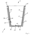
- the generally marked by the reference numeral 1 container system has a first container 3 and an inserted into the first container second container 5, each made of deep-drawn polystyrene are.
- the first container 3 has a rectangular bottom 3b from which extends four side walls extend upwards.
- Figure 1 alone are the left Side wall 3l and the right side wall 3r to recognize.
- the side walls 3l and 3r extend slightly outwardly inclined to the opening 9 of the first Container 3.
- the second container 5 introduced into the first container 3 has a thereto essentially complementary shape. It consists of a rectangular Floor 5b, from which four side walls, slightly inclined outwards until to the opening 9 of the container 5 extend; in Figure 1 are of the four Side walls turn alone the left side wall 5l and the right Sidewall 5r shown.
- the second container 5 lies with the outer surface 11 of its wall (from the in Figure 1, the bottom 5b and the side walls 5l, 5r are shown) on the Inner surface 13 of the wall (from that in Figure 1, the bottom 3b and side walls 3l, 3r are shown) of the first container 3 at.
- the side walls 5l, 5r of the second container 5 project beyond the side walls 3l, 3r of the first container 3 upwards and have at their upper, the Opening 9 forming an outwardly facing portion 15, on a (not shown) lid can be clipped.
Landscapes
- Engineering & Computer Science (AREA)
- Mechanical Engineering (AREA)
- Packages (AREA)
- Centrifugal Separators (AREA)
- Closures For Containers (AREA)
- Refuse Receptacles (AREA)
Abstract
Description
- einem ersten Behälter aus Kunststoff und
- einem zweiten Behälter aus Kunststoff, wobei
- der zweite Behälter in den ersten Behälter einführbar ist, so dass die Öffnungen der Behälter jeweils zur gleichen Seite hin gerichtet sind und
- der zweite Behälter zumindest abschnittsweise mit der Außenfläche seiner Wand an der Innenfläche der Wand des ersten Behälters anliegt.
- Figur 1:
- ein Behältersystem in seitlicher Schnittansicht.
Claims (5)
- Behältersystem mita) einem ersten Behälter (3) aus Kunststoff undb) einem zweiten Behälter (5) aus Kunststoff, wobeic) der zweite (5) Behälter in den ersten Behälter (3) einführbar ist, so dass die Öffnungen (9) der Behälter (3, 5) jeweils zur gleichen Seite hin gerichtet sind undd) der zweite Behälter (5) zumindest abschnittsweise mit der Außenfläche (11) seiner Wand (5l, 5b, 5r) an der Innenfläche (13) der Wand (31, 3b, 3r) des ersten Behälters (3) anliegt.
- Behältersystem nach Anspruch 1, bei dem der erste Behälter (3) eine größere Wandstärke aufweist als der zweite Behälter (5).
- Behältersystem nach Anspruch 1 mit einem formstabilen zweiten Behälter (5).
- Behältersystem nach Anspruch 1, bei dem der zweite Behälter (5) mittels Tiefziehen hergestellt worden ist.
- Behältersystem nach Anspruch 1, bei dem der zweite Behälter (5) aus Polystyrol, Polyethylen oder Polypropylen besteht.
Priority Applications (1)
| Application Number | Priority Date | Filing Date | Title |
|---|---|---|---|
| SI200430221T SI1541503T1 (sl) | 2003-12-09 | 2004-11-19 | Sistem vsebnikov |
Applications Claiming Priority (2)
| Application Number | Priority Date | Filing Date | Title |
|---|---|---|---|
| DE10357397 | 2003-12-09 | ||
| DE10357397A DE10357397B4 (de) | 2003-12-09 | 2003-12-09 | Behältersystem |
Publications (2)
| Publication Number | Publication Date |
|---|---|
| EP1541503A1 true EP1541503A1 (de) | 2005-06-15 |
| EP1541503B1 EP1541503B1 (de) | 2006-12-13 |
Family
ID=34485267
Family Applications (1)
| Application Number | Title | Priority Date | Filing Date |
|---|---|---|---|
| EP04027484A Expired - Lifetime EP1541503B1 (de) | 2003-12-09 | 2004-11-19 | Behältersystem |
Country Status (5)
| Country | Link |
|---|---|
| EP (1) | EP1541503B1 (de) |
| AT (1) | ATE348059T1 (de) |
| DE (2) | DE10357397B4 (de) |
| ES (1) | ES2277187T3 (de) |
| SI (1) | SI1541503T1 (de) |
Citations (8)
| Publication number | Priority date | Publication date | Assignee | Title |
|---|---|---|---|---|
| CH377716A (de) * | 1959-11-19 | 1964-05-15 | Boetsch Karl | Kehrichteimer-Einsatz |
| NL7213852A (de) * | 1972-10-12 | 1974-04-16 | ||
| DE9106088U1 (de) * | 1991-05-17 | 1991-08-14 | Hager, Wolfgang, 32839 Steinheim | Behälter mit einer im Hohlkörper-Blasverfahren paßgenau eingesetzten Folie |
| DE4020170A1 (de) * | 1990-05-11 | 1991-11-14 | Entsorgungstechnik Berlin Gmbh | Vorrichtung fuer behaelter aus kunststoff |
| DE9203581U1 (de) * | 1992-03-17 | 1992-05-07 | Pawlicki, Marc, 7440 Nürtingen | Abfallbehälter |
| DE4126964A1 (de) * | 1991-08-14 | 1993-02-18 | Spies Lutz Volker | Umweltfreundliches behaeltersystem fuer lacke, farben und dergleichen, sowie verfahren zur wiederverwertung des behaeltersystems |
| US5236102A (en) * | 1990-12-21 | 1993-08-17 | Sto Aktiengesellschaft | Re-usable container |
| US5415180A (en) * | 1993-11-03 | 1995-05-16 | Devon Industries, Inc. | System and kit for medical procedures |
Family Cites Families (3)
| Publication number | Priority date | Publication date | Assignee | Title |
|---|---|---|---|---|
| DE1916766U (de) * | 1965-03-30 | 1965-05-26 | Eisenwerk Sauerland G M B H | Einsatzeimer fuer abfalleimer. |
| JPH0649521B2 (ja) * | 1986-11-14 | 1994-06-29 | レベルト,ヨハネス | 衛生廃棄物回収装置 |
| FR2811307B1 (fr) * | 2000-07-06 | 2002-12-06 | Rossignol Sa | Poubelle destinee a recevoir un sac souple de collecte des dechets |
-
2003
- 2003-12-09 DE DE10357397A patent/DE10357397B4/de not_active Expired - Lifetime
-
2004
- 2004-11-19 ES ES04027484T patent/ES2277187T3/es not_active Expired - Lifetime
- 2004-11-19 DE DE502004002285T patent/DE502004002285D1/de not_active Expired - Lifetime
- 2004-11-19 EP EP04027484A patent/EP1541503B1/de not_active Expired - Lifetime
- 2004-11-19 SI SI200430221T patent/SI1541503T1/sl unknown
- 2004-11-19 AT AT04027484T patent/ATE348059T1/de active
Patent Citations (8)
| Publication number | Priority date | Publication date | Assignee | Title |
|---|---|---|---|---|
| CH377716A (de) * | 1959-11-19 | 1964-05-15 | Boetsch Karl | Kehrichteimer-Einsatz |
| NL7213852A (de) * | 1972-10-12 | 1974-04-16 | ||
| DE4020170A1 (de) * | 1990-05-11 | 1991-11-14 | Entsorgungstechnik Berlin Gmbh | Vorrichtung fuer behaelter aus kunststoff |
| US5236102A (en) * | 1990-12-21 | 1993-08-17 | Sto Aktiengesellschaft | Re-usable container |
| DE9106088U1 (de) * | 1991-05-17 | 1991-08-14 | Hager, Wolfgang, 32839 Steinheim | Behälter mit einer im Hohlkörper-Blasverfahren paßgenau eingesetzten Folie |
| DE4126964A1 (de) * | 1991-08-14 | 1993-02-18 | Spies Lutz Volker | Umweltfreundliches behaeltersystem fuer lacke, farben und dergleichen, sowie verfahren zur wiederverwertung des behaeltersystems |
| DE9203581U1 (de) * | 1992-03-17 | 1992-05-07 | Pawlicki, Marc, 7440 Nürtingen | Abfallbehälter |
| US5415180A (en) * | 1993-11-03 | 1995-05-16 | Devon Industries, Inc. | System and kit for medical procedures |
Also Published As
| Publication number | Publication date |
|---|---|
| EP1541503B1 (de) | 2006-12-13 |
| ATE348059T1 (de) | 2007-01-15 |
| DE10357397A1 (de) | 2005-08-11 |
| SI1541503T1 (sl) | 2007-06-30 |
| DE502004002285D1 (de) | 2007-01-25 |
| DE10357397B4 (de) | 2006-07-13 |
| ES2277187T3 (es) | 2007-07-01 |
Similar Documents
| Publication | Publication Date | Title |
|---|---|---|
| DE3804048C2 (de) | Behälter zum Sammeln von Körperausscheidungen | |
| DE1900244A1 (de) | Oben offener Behaelter zur Aufnahme im wesentlichen festen Gutes | |
| DE69306258T2 (de) | Gewellter thermoplastischer zuschnitt für einen behälter | |
| CH620166A5 (de) | ||
| CH687252A5 (de) | Gebinde mit einsteckbarer Verschlusseinheit. | |
| DE2659275A1 (de) | Behaelter fuer fluessigkeiten | |
| DE102017107675A1 (de) | Behälter aus Kunststoff mit In-Mould-Label | |
| EP1541503B1 (de) | Behältersystem | |
| CH650210A5 (de) | Konservendose mit dosenkoerper aus weissblech. | |
| DE102016123921A1 (de) | Dichtelement zur Abdichtung einer Wannenecke gegenüber einer Baukonstruktion und Verfahren dafür | |
| DE202011050589U1 (de) | Schale für Spieße | |
| DE3872327T2 (de) | Metallische vorrichtung zum sammeln von krankenhausabfall. | |
| DE3435666A1 (de) | Einrichtung zur vorsortierung von muell | |
| DE69501104T2 (de) | Wiederverwendbare verpackungsschachtel | |
| DE8710452U1 (de) | Verschließbarer Behälter zur Aufnahme von infektiösen Abfällen, Körperteilen und Organabfällen | |
| DE3242305C2 (de) | Behälter aus Kunststoff oder Leichtmetall | |
| EP0098981A2 (de) | Schwimmende Kräuterpackung | |
| DE102015104015B4 (de) | Behälter zur Aufnahme von Lebensmitteln und Verfahren zur Herstellung desselben | |
| EP1922255A1 (de) | Schlauchbeutel mit aufreissbarem schlauchbeutelkörper | |
| DE9307217U1 (de) | Sterilisationsdoppelsack für infektiösen Müll | |
| WO1997048609A1 (de) | Karton-rohrabschluss, sowie dose und dosendeckel damit | |
| DE3247759A1 (de) | Verformbarer behaelter mit fuellarmatur | |
| DE102011075142A1 (de) | Aufwickelvorrichtung | |
| DE19649787A1 (de) | Verpackung, insbesondere ökologische Verpackung, mit veränderbarem Volumen | |
| EP0536517A2 (de) | Durch Tiefziehen hergestellter Kunststoffbehälter |
Legal Events
| Date | Code | Title | Description |
|---|---|---|---|
| PUAI | Public reference made under article 153(3) epc to a published international application that has entered the european phase |
Free format text: ORIGINAL CODE: 0009012 |
|
| AK | Designated contracting states |
Kind code of ref document: A1 Designated state(s): AT BE BG CH CY CZ DE DK EE ES FI FR GB GR HU IE IS IT LI LU MC NL PL PT RO SE SI SK TR |
|
| AX | Request for extension of the european patent |
Extension state: AL HR LT LV MK YU |
|
| 17P | Request for examination filed |
Effective date: 20050624 |
|
| AKX | Designation fees paid |
Designated state(s): AT BE BG CH CY CZ DE DK EE ES FI FR GB GR HU IE IS IT LI LU MC NL PL PT RO SE SI SK TR |
|
| GRAP | Despatch of communication of intention to grant a patent |
Free format text: ORIGINAL CODE: EPIDOSNIGR1 |
|
| GRAS | Grant fee paid |
Free format text: ORIGINAL CODE: EPIDOSNIGR3 |
|
| GRAA | (expected) grant |
Free format text: ORIGINAL CODE: 0009210 |
|
| AK | Designated contracting states |
Kind code of ref document: B1 Designated state(s): AT BE BG CH CY CZ DE DK EE ES FI FR GB GR HU IE IS IT LI LU MC NL PL PT RO SE SI SK TR |
|
| PG25 | Lapsed in a contracting state [announced via postgrant information from national office to epo] |
Ref country code: PL Free format text: LAPSE BECAUSE OF FAILURE TO SUBMIT A TRANSLATION OF THE DESCRIPTION OR TO PAY THE FEE WITHIN THE PRESCRIBED TIME-LIMIT Effective date: 20061213 Ref country code: IE Free format text: LAPSE BECAUSE OF FAILURE TO SUBMIT A TRANSLATION OF THE DESCRIPTION OR TO PAY THE FEE WITHIN THE PRESCRIBED TIME-LIMIT Effective date: 20061213 Ref country code: RO Free format text: LAPSE BECAUSE OF FAILURE TO SUBMIT A TRANSLATION OF THE DESCRIPTION OR TO PAY THE FEE WITHIN THE PRESCRIBED TIME-LIMIT Effective date: 20061213 Ref country code: DK Free format text: LAPSE BECAUSE OF FAILURE TO SUBMIT A TRANSLATION OF THE DESCRIPTION OR TO PAY THE FEE WITHIN THE PRESCRIBED TIME-LIMIT Effective date: 20061213 Ref country code: CZ Free format text: LAPSE BECAUSE OF FAILURE TO SUBMIT A TRANSLATION OF THE DESCRIPTION OR TO PAY THE FEE WITHIN THE PRESCRIBED TIME-LIMIT Effective date: 20061213 Ref country code: FI Free format text: LAPSE BECAUSE OF FAILURE TO SUBMIT A TRANSLATION OF THE DESCRIPTION OR TO PAY THE FEE WITHIN THE PRESCRIBED TIME-LIMIT Effective date: 20061213 Ref country code: SK Free format text: LAPSE BECAUSE OF FAILURE TO SUBMIT A TRANSLATION OF THE DESCRIPTION OR TO PAY THE FEE WITHIN THE PRESCRIBED TIME-LIMIT Effective date: 20061213 |
|
| REG | Reference to a national code |
Ref country code: GB Ref legal event code: FG4D Free format text: NOT ENGLISH |
|
| REG | Reference to a national code |
Ref country code: CH Ref legal event code: EP |
|
| REG | Reference to a national code |
Ref country code: IE Ref legal event code: FG4D Free format text: LANGUAGE OF EP DOCUMENT: GERMAN |
|
| REF | Corresponds to: |
Ref document number: 502004002285 Country of ref document: DE Date of ref document: 20070125 Kind code of ref document: P |
|
| PG25 | Lapsed in a contracting state [announced via postgrant information from national office to epo] |
Ref country code: SE Free format text: LAPSE BECAUSE OF FAILURE TO SUBMIT A TRANSLATION OF THE DESCRIPTION OR TO PAY THE FEE WITHIN THE PRESCRIBED TIME-LIMIT Effective date: 20070313 Ref country code: BG Free format text: LAPSE BECAUSE OF FAILURE TO SUBMIT A TRANSLATION OF THE DESCRIPTION OR TO PAY THE FEE WITHIN THE PRESCRIBED TIME-LIMIT Effective date: 20070313 |
|
| REG | Reference to a national code |
Ref country code: CH Ref legal event code: NV Representative=s name: HANS RUDOLF GACHNANG PATENTANWALT |
|
| GBT | Gb: translation of ep patent filed (gb section 77(6)(a)/1977) |
Effective date: 20070309 |
|
| PG25 | Lapsed in a contracting state [announced via postgrant information from national office to epo] |
Ref country code: IS Free format text: LAPSE BECAUSE OF FAILURE TO SUBMIT A TRANSLATION OF THE DESCRIPTION OR TO PAY THE FEE WITHIN THE PRESCRIBED TIME-LIMIT Effective date: 20070413 |
|
| REG | Reference to a national code |
Ref country code: GR Ref legal event code: EP Ref document number: 20070400816 Country of ref document: GR |
|
| PG25 | Lapsed in a contracting state [announced via postgrant information from national office to epo] |
Ref country code: PT Free format text: LAPSE BECAUSE OF FAILURE TO SUBMIT A TRANSLATION OF THE DESCRIPTION OR TO PAY THE FEE WITHIN THE PRESCRIBED TIME-LIMIT Effective date: 20070514 |
|
| ET | Fr: translation filed | ||
| REG | Reference to a national code |
Ref country code: ES Ref legal event code: FG2A Ref document number: 2277187 Country of ref document: ES Kind code of ref document: T3 |
|
| PLBE | No opposition filed within time limit |
Free format text: ORIGINAL CODE: 0009261 |
|
| STAA | Information on the status of an ep patent application or granted ep patent |
Free format text: STATUS: NO OPPOSITION FILED WITHIN TIME LIMIT |
|
| 26N | No opposition filed |
Effective date: 20070914 |
|
| PG25 | Lapsed in a contracting state [announced via postgrant information from national office to epo] |
Ref country code: MC Free format text: LAPSE BECAUSE OF NON-PAYMENT OF DUE FEES Effective date: 20071130 |
|
| PG25 | Lapsed in a contracting state [announced via postgrant information from national office to epo] |
Ref country code: EE Free format text: LAPSE BECAUSE OF FAILURE TO SUBMIT A TRANSLATION OF THE DESCRIPTION OR TO PAY THE FEE WITHIN THE PRESCRIBED TIME-LIMIT Effective date: 20061213 |
|
| PG25 | Lapsed in a contracting state [announced via postgrant information from national office to epo] |
Ref country code: CY Free format text: LAPSE BECAUSE OF FAILURE TO SUBMIT A TRANSLATION OF THE DESCRIPTION OR TO PAY THE FEE WITHIN THE PRESCRIBED TIME-LIMIT Effective date: 20061213 |
|
| PG25 | Lapsed in a contracting state [announced via postgrant information from national office to epo] |
Ref country code: TR Free format text: LAPSE BECAUSE OF FAILURE TO SUBMIT A TRANSLATION OF THE DESCRIPTION OR TO PAY THE FEE WITHIN THE PRESCRIBED TIME-LIMIT Effective date: 20061213 Ref country code: HU Free format text: LAPSE BECAUSE OF FAILURE TO SUBMIT A TRANSLATION OF THE DESCRIPTION OR TO PAY THE FEE WITHIN THE PRESCRIBED TIME-LIMIT Effective date: 20070614 |
|
| REG | Reference to a national code |
Ref country code: CH Ref legal event code: NV Representative=s name: GACHNANG AG PATENTANWAELTE, CH |
|
| REG | Reference to a national code |
Ref country code: FR Ref legal event code: PLFP Year of fee payment: 12 |
|
| REG | Reference to a national code |
Ref country code: FR Ref legal event code: PLFP Year of fee payment: 13 |
|
| REG | Reference to a national code |
Ref country code: FR Ref legal event code: PLFP Year of fee payment: 14 |
|
| PGFP | Annual fee paid to national office [announced via postgrant information from national office to epo] |
Ref country code: NL Payment date: 20221118 Year of fee payment: 19 Ref country code: LU Payment date: 20221118 Year of fee payment: 19 Ref country code: IT Payment date: 20221130 Year of fee payment: 19 Ref country code: GB Payment date: 20221123 Year of fee payment: 19 Ref country code: FR Payment date: 20221118 Year of fee payment: 19 Ref country code: ES Payment date: 20221216 Year of fee payment: 19 Ref country code: DE Payment date: 20221018 Year of fee payment: 19 Ref country code: AT Payment date: 20221117 Year of fee payment: 19 |
|
| PGFP | Annual fee paid to national office [announced via postgrant information from national office to epo] |
Ref country code: SI Payment date: 20221107 Year of fee payment: 19 Ref country code: GR Payment date: 20221118 Year of fee payment: 19 Ref country code: CH Payment date: 20221124 Year of fee payment: 19 Ref country code: BE Payment date: 20221118 Year of fee payment: 19 |
|
| REG | Reference to a national code |
Ref country code: CH Ref legal event code: PK Free format text: BERICHTIGUNGEN |
|
| REG | Reference to a national code |
Ref country code: DE Ref legal event code: R119 Ref document number: 502004002285 Country of ref document: DE |
|
| REG | Reference to a national code |
Ref country code: CH Ref legal event code: PL |
|
| REG | Reference to a national code |
Ref country code: NL Ref legal event code: MM Effective date: 20231201 |
|
| PG25 | Lapsed in a contracting state [announced via postgrant information from national office to epo] |
Ref country code: LU Free format text: LAPSE BECAUSE OF NON-PAYMENT OF DUE FEES Effective date: 20231119 Ref country code: GR Free format text: LAPSE BECAUSE OF NON-PAYMENT OF DUE FEES Effective date: 20240610 |
|
| REG | Reference to a national code |
Ref country code: AT Ref legal event code: MM01 Ref document number: 348059 Country of ref document: AT Kind code of ref document: T Effective date: 20231119 |
|
| PG25 | Lapsed in a contracting state [announced via postgrant information from national office to epo] |
Ref country code: CH Free format text: LAPSE BECAUSE OF NON-PAYMENT OF DUE FEES Effective date: 20231130 |
|
| PG25 | Lapsed in a contracting state [announced via postgrant information from national office to epo] |
Ref country code: AT Free format text: LAPSE BECAUSE OF NON-PAYMENT OF DUE FEES Effective date: 20231119 |
|
| GBPC | Gb: european patent ceased through non-payment of renewal fee |
Effective date: 20231119 |
|
| PG25 | Lapsed in a contracting state [announced via postgrant information from national office to epo] |
Ref country code: LU Free format text: LAPSE BECAUSE OF NON-PAYMENT OF DUE FEES Effective date: 20231119 Ref country code: GR Free format text: LAPSE BECAUSE OF NON-PAYMENT OF DUE FEES Effective date: 20240610 Ref country code: CH Free format text: LAPSE BECAUSE OF NON-PAYMENT OF DUE FEES Effective date: 20231130 Ref country code: AT Free format text: LAPSE BECAUSE OF NON-PAYMENT OF DUE FEES Effective date: 20231119 Ref country code: SI Free format text: LAPSE BECAUSE OF NON-PAYMENT OF DUE FEES Effective date: 20231120 |
|
| REG | Reference to a national code |
Ref country code: BE Ref legal event code: MM Effective date: 20231130 |
|
| PG25 | Lapsed in a contracting state [announced via postgrant information from national office to epo] |
Ref country code: NL Free format text: LAPSE BECAUSE OF NON-PAYMENT OF DUE FEES Effective date: 20231201 |
|
| PG25 | Lapsed in a contracting state [announced via postgrant information from national office to epo] |
Ref country code: NL Free format text: LAPSE BECAUSE OF NON-PAYMENT OF DUE FEES Effective date: 20231201 |
|
| REG | Reference to a national code |
Ref country code: SI Ref legal event code: KO00 Effective date: 20240813 |
|
| PG25 | Lapsed in a contracting state [announced via postgrant information from national office to epo] |
Ref country code: DE Free format text: LAPSE BECAUSE OF NON-PAYMENT OF DUE FEES Effective date: 20240601 |
|
| PG25 | Lapsed in a contracting state [announced via postgrant information from national office to epo] |
Ref country code: GB Free format text: LAPSE BECAUSE OF NON-PAYMENT OF DUE FEES Effective date: 20231119 |
|
| PG25 | Lapsed in a contracting state [announced via postgrant information from national office to epo] |
Ref country code: BE Free format text: LAPSE BECAUSE OF NON-PAYMENT OF DUE FEES Effective date: 20231130 |
|
| PG25 | Lapsed in a contracting state [announced via postgrant information from national office to epo] |
Ref country code: FR Free format text: LAPSE BECAUSE OF NON-PAYMENT OF DUE FEES Effective date: 20231130 |
|
| PG25 | Lapsed in a contracting state [announced via postgrant information from national office to epo] |
Ref country code: GB Free format text: LAPSE BECAUSE OF NON-PAYMENT OF DUE FEES Effective date: 20231119 Ref country code: FR Free format text: LAPSE BECAUSE OF NON-PAYMENT OF DUE FEES Effective date: 20231130 Ref country code: DE Free format text: LAPSE BECAUSE OF NON-PAYMENT OF DUE FEES Effective date: 20240601 Ref country code: BE Free format text: LAPSE BECAUSE OF NON-PAYMENT OF DUE FEES Effective date: 20231130 |
|
| PG25 | Lapsed in a contracting state [announced via postgrant information from national office to epo] |
Ref country code: IT Free format text: LAPSE BECAUSE OF NON-PAYMENT OF DUE FEES Effective date: 20231119 |
|
| PG25 | Lapsed in a contracting state [announced via postgrant information from national office to epo] |
Ref country code: IT Free format text: LAPSE BECAUSE OF NON-PAYMENT OF DUE FEES Effective date: 20231119 |
|
| REG | Reference to a national code |
Ref country code: ES Ref legal event code: FD2A Effective date: 20250103 |
|
| PG25 | Lapsed in a contracting state [announced via postgrant information from national office to epo] |
Ref country code: ES Free format text: LAPSE BECAUSE OF NON-PAYMENT OF DUE FEES Effective date: 20231120 |
|
| PG25 | Lapsed in a contracting state [announced via postgrant information from national office to epo] |
Ref country code: ES Free format text: LAPSE BECAUSE OF NON-PAYMENT OF DUE FEES Effective date: 20231120 |