EP1541503B1 - Behältersystem - Google Patents
Behältersystem Download PDFInfo
- Publication number
- EP1541503B1 EP1541503B1 EP04027484A EP04027484A EP1541503B1 EP 1541503 B1 EP1541503 B1 EP 1541503B1 EP 04027484 A EP04027484 A EP 04027484A EP 04027484 A EP04027484 A EP 04027484A EP 1541503 B1 EP1541503 B1 EP 1541503B1
- Authority
- EP
- European Patent Office
- Prior art keywords
- container
- wall
- sack
- lid
- containers
- Prior art date
- Legal status (The legal status is an assumption and is not a legal conclusion. Google has not performed a legal analysis and makes no representation as to the accuracy of the status listed.)
- Expired - Lifetime
Links
- 239000004033 plastic Substances 0.000 claims abstract description 9
- 229920003023 plastic Polymers 0.000 claims abstract description 9
- -1 polyethylene Polymers 0.000 claims description 4
- 239000004793 Polystyrene Substances 0.000 claims description 3
- 229920002223 polystyrene Polymers 0.000 claims description 3
- 239000004698 Polyethylene Substances 0.000 claims description 2
- 239000004743 Polypropylene Substances 0.000 claims description 2
- 229920000573 polyethylene Polymers 0.000 claims description 2
- 229920001155 polypropylene Polymers 0.000 claims description 2
- 239000002699 waste material Substances 0.000 description 9
- 241001631457 Cannula Species 0.000 description 3
- 239000002906 medical waste Substances 0.000 description 3
- 229920000642 polymer Polymers 0.000 description 2
- 230000000295 complement effect Effects 0.000 description 1
- 239000007788 liquid Substances 0.000 description 1
- 239000002184 metal Substances 0.000 description 1
- 238000010408 sweeping Methods 0.000 description 1
- 239000012815 thermoplastic material Substances 0.000 description 1
Images
Classifications
-
- B—PERFORMING OPERATIONS; TRANSPORTING
- B65—CONVEYING; PACKING; STORING; HANDLING THIN OR FILAMENTARY MATERIAL
- B65F—GATHERING OR REMOVAL OF DOMESTIC OR LIKE REFUSE
- B65F1/00—Refuse receptacles; Accessories therefor
- B65F1/04—Refuse receptacles; Accessories therefor with removable inserts
- B65F1/08—Refuse receptacles; Accessories therefor with removable inserts with rigid inserts
Definitions
- the invention relates to a container system, in particular a container system for receiving hospital waste, according to the preamble of claim 1.
- lid sack systems For receiving waste, in particular for receiving hospital waste, so-called lid sack systems are often used.
- a lid sack system consists of an outer container made of metal or plastic, in which a bag is hung. To attach the bag to the container, the bag is slipped over the upper edge of the container. In this state, the bag is filled with waste.
- the filled sack is removed from the container by squeezing a sack lid onto the area of the sack which is slipped over the edge of the container.
- the bag is thereby clamped to the bag lid, so that it can be removed from the container and disposed of.
- the weak point of this system is in particular the low strength of the bag.
- This can be damaged or pierced by waste, for example used cannulas.
- waste for example used cannulas.
- This not only waste, such as liquids, can escape from the bag to the outside, but it can also be injured persons, for example, by cannulas that protrude through the blind skin to the outside.
- the aforementioned problems arise in particular even when the bag has been removed from the container through the bag lid.
- the invention has for its object to provide a system for receiving waste, especially hospital waste, available through the waste can be taken safer than by the previously used lid sack systems.
- WO 02/085757 A1 discloses to replace the sack against an inherently stable container in a lid sack system, according to the preamble of claim 1.
- Swiss Patent No. 377716 discloses an insert for a sweeping bucket having a wall thickness of 0.2 to 0 , 3mm.
- DE 91 06 088 U1 discloses a container with a precisely inserted into its interior film with a thickness between 0.03 and 0.08 mm.
- container is understood to mean a dimensionally stable container, that is to say in particular an inherently stable container which retains its shape (in particular under its own weight) and does not collapse (like a sack) under its own weight.
- Corresponding containers can be made of plastic, even with very small wall thicknesses.
- the second container (inner container) has a wall thickness of 0.08 to 0.3 mm, that is, for example, a wall thickness in the range of 0.1 to 0.2 mm (these wall thicknesses are average values; Give areas in which the wall thickness of the second container is above or below).
- the second container is insertable into the first container so that the openings of both containers are respectively directed to the same side.
- the second container can be inserted into the first container such that the first container (as an outer container) the second Containers (as an inner container), wherein both containers are open to the same side.
- This system resembles two nested containers from an outer, larger container (first container) and an inner, smaller container (second container), the opening facing the same side.
- the second container in the state in which the second container is inserted into the first container, the second container can be filled with waste.
- the second container is much more resistant to wastes, for example, cannulas than a sack, is presumably due to it giving less to the pressure of garbage than a (more flexible) sack.
- the second container rests with the outer surface of its wall over its entire surface on the inner surface of the wall of the first container. However, it may be sufficient for the second container to bear against the inner surface of the wall of the first container by at least 90%, or at least 80%, or at least only 70% of the outer surface of its wall.
- both containers Due to the dimensional stability (inherent stability) of the first and the second container, both containers "mutually support” and form a very stable overall system when inserted one inside the other. This results in that the first container (outer container) can be produced with a smaller wall thickness and thus more cost-effective than the container in a lid sack system, since the sack in the latter system can not contribute to the stability.
- the first container has a greater wall thickness (wall thickness) than the second container.
- the wall thickness of the first container is in the range of 0.2 to 0.5 mm, that is, for example, in the range of 0.2 to 0.4 mm.
- first container and the second container are basically arbitrary.
- both containers may have a substantially cylindrical (barrel-like) or box-like shape.
- the containers may also expand from their bottom to the opening.
- the first container and the second container may, for example, each have a round or rectangular bottom, from which side walls each extend up to the opening of the container.
- the bottom and side walls of the container form its wall.
- the wall of the first and the second container can be formed profiled, so for example projecting and / or recessed areas. These areas, which can be arranged for example in the side wall and extend from the bottom in the direction of the opening, can increase the stability (rigidity) of the respective container.
- the profiled areas of the wall of the first and second container can of course be formed corresponding to each other, so that even with corresponding profiled trained walls (especially for example in the corresponding profiled trained wall sections) of the second container at least partially with the outer surface of its wall on the Inner surface of the wall of the first container rests.
- both containers can be given a defined and very precise contour, so that it is ensured that defined sections of the outer surface of the wall of the second container bear against the inner surface of the wall of the first container.
- the first container and the second container may be made of any plastic, but preferably of a thermoplastic material, for example polystyrene, polyethylene or polypropylene.
- the container system can be designed such that the second container can be closed by a lid, preferably a plastic lid.
- the edge of the opening of the second container can be designed such that the lid can be "clipped” onto this edge, that is, can snap into place at the edge of the opening of the second container.
- the lid may for example also have the task of being able to extract the second container with the aid of the lid from the first container, in particular when the second container is filled with waste and must be disposed of.
- the first container which is designed to receive a second (inner) container, then a new (empty) second container can be used.
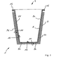
- the container system designated overall by the reference numeral 1, has a first container 3 and a second container 5 introduced into the first container, each made of deep-drawn polystyrene.
- the first container 3 has a rectangular bottom 3b, from which four side walls extend upwards. In Figure 1, only the left side wall 3l and the right side wall 3r can be seen. The side walls 3l and 3r extend slightly outwardly inclined to the opening 9 of the first container. 3
- the introduced into the first container 3 second container 5 has a substantially complementary thereto for this purpose. It consists of a rectangular bottom 5b, from which four side walls, slightly inclined outwards, to the opening 9 of the container 5 extend; In FIG. 1, the left side wall 5l and the right side wall 5r are again shown as the only ones of the four side walls.
- the second container 5 lies with the outer surface 11 of its wall (of which the bottom 5b and the side walls 5l, 5r are shown in Figure 1) on the inner surface 13 of the wall (from the bottom 3b and side walls 3l, 3r of Figure 1) are) of the first container 3 at.
- the side walls 51, 5r of the second container 5 project beyond the side walls 31, 3r of the first container 3 and have at their upper, the opening 9 forming edge on an outwardly facing portion 15, on which a (not shown) lid clipped can be.
Landscapes
- Engineering & Computer Science (AREA)
- Mechanical Engineering (AREA)
- Packages (AREA)
- Centrifugal Separators (AREA)
- Closures For Containers (AREA)
- Refuse Receptacles (AREA)
Description
- Die Erfindung betrifft ein Behältersystem, insbesondere ein Behältersystem zur Aufnahme von Krankenhausabfällen, gemäß dem Oberbegriff des Anspruchs 1.
- Zur Aufnahme von Abfällen, insbesondere zur Aufnahme von Krankenhausabfällen, werden häufig sogenannte Deckelsack-Systeme verwendet.
- Ein Deckelsack-System besteht aus einem äußeren Behälter aus Metall oder Kunststoff, in den ein Sack eingehängt ist. Zur Befestigung des Sacks am Behälter wird der Sack über den oberen Rand des Behälters gestülpt. In diesem Zustand wird der Sack mit Abfällen befüllt.
- Der gefüllte Sack wird dem Behälter entnommen, indem ein Sack-Deckel auf den Bereich des Sacks aufgedrückt wird, der über den Rand des Behälters gestülpt ist. Der Sack wird dadurch am Sack-Deckel festgeklemmt, so dass er dem Behälter entnommen und entsorgt werden kann.
- Schwachpunkt dieses Systems ist insbesondere die geringe Festigkeit des Sacks. Dieser kann durch Abfälle, beispielsweise gebrauchte Kanülen, beschädigt beziehungsweise durchstoßen werden. Dadurch können nicht nur Abfälle, wie beispielsweise Flüssigkeiten, aus dem Sack nach außen dringen, sondern es können auch Personen verletzt werden, beispielsweise durch Kanülen, die durch die Sackhaut nach außen ragen. Die vorgenannten Probleme ergeben sich insbesondere auch dann, wenn der Sack durch den Sack-Deckel dem Behälter entnommen worden ist.
- Der Erfindung liegt die Aufgabe zugrunde, ein System zur Aufnahme von Abfällen, insbesondere Krankenhausabfällen, zur Verfügung zu stellen, durch das Abfall sicherer aufgenommen werden kann als durch die bisher verwendeten Deckelsack-Systeme.
- WO 02/085757 A1 offenbart, bei einem Deckelsack-System den Sack gegen einen eigenstabilen Behälter auszutauschen, gemäß Oberbegriff nach Anspruch 1. In der Schweizer Patentschrift Nr. 377716 wird ein Einsatz für einen Kehrrichteimer offenbart, der eine Wandstärke von 0,2 bis 0,3mm aufweist. DE 91 06 088 U1 offenbart einen Behälter mit einer in seinen Innenraum passgenau eingesetzten Folie mit einer Dicke zwischen 0,03 und 0,08mm.
- Erfindungsgemäß wird die Aufgabe gelöst durch ein Behältersystem mit
- einem ersten Behälter aus Kunststoff und
- einem zweiten Behälter aus Kunststoff, wobei
- der zweite Behälter in den ersten Behälter einführbar ist, so dass die Öffnungen der Behälter jeweils zur gleichen Seite hin gerichtet sind und
- der zweite Behälter zumindest abschnittsweise mit der Außenfläche seiner Wand an der Innenfläche der Wand des ersten Behälters anliegt,
- und wobei der erste und der zweite Behälter die Wandstärken nach Anspruch 1 aufweisen.
- Unter "Behälter" wird anmeldungsgemäß ein formstabiles Behältnis verstanden, also insbesondere ein eigenstabiles Behältnis, das seine Form (insbesondere unter Eigengewicht) beibehält und nicht (wie ein Sack) unter seinem eigenen Gewicht in sich zusammenfällt.
- Entsprechende Behälter lassen sich, auch mit sehr geringen Wandstärken, aus Kunststoff herstellen.
- Erfindungsgemäß weist der zweite Behälter (innere Behälter) eine Wandstärke von 0,08 bis 0,3 mm auf, also beispielsweise auch eine Wandstärke im Bereich von 0,1 bis 0,2 mm (diese Wandstärken verstehen sich als Durchschnittswerte; es kann selbstverständlich auch Bereiche geben, in denen die Wandstärke des zweiten Behälters darüber oder darunter liegt).
- Bereits diese geringe Wandstärke ist ausreichend, dem zweiten Behälter die geforderte Eigenstabilität zu verleihen.
- Der zweite Behälter ist in den ersten Behälter einführbar, so dass die Öffnungen beider Behälter jeweils zur gleichen Seite hin gerichtet sind Mit anderen Worten: Der zweite Behälter kann derart in den ersten Behälter eingeführt werden, dass der erste Behälter (als äußerer Behälter) den zweiten Behälter (als innerem Behälter) umfängt, wobei beide Behälter zur gleichen Seite hin geöffnet sind. Dieses System gleicht damit zwei ineinander gestülpten Behältern aus einem äußeren, größeren Behälter (ersten Behälter) und einem inneren, kleineren Behälter (zweiten Behälter), deren Öffnung zur gleichen Seite hin weist.
- Dadurch kann in dem Zustand, in dem der zweite Behälter in den ersten Behälter eingeführt ist, der zweite Behälter mit Abfall befüllt werden.
- Die Tatsache, dass der zweite Behälter wesentlich widerstandsfähiger gegenüber Abfällen, zum Beispiel Kanülen, ist als ein Sack, beruht vermutlich darauf, dass er dem Druck von Abfall weniger nachgibt als ein (flexiblerer) Sack.
- Diese - gegenüber einem Sack - erhöhte Stabilität des zweiten Behälters ist dadurch erreichs, weil der zweite Behälter zumindest abschnittsweise mit der Außenfläche seiner Wand an der Innenfläche der Wand des ersten Behälters anliegt. Dadurch wird die Wand des zweiten Behälters zusätzlich verstärkt, und seine Festigkeit zusätzlich erhöht.
- Es kann vorgesehen sein, dass der zweite Behälter mit der Außenfläche seiner Wand vollflächig an der Innenfläche der Wand des ersten Behälters anliegt. Es kann jedoch ausreichend sein, dass der zweite Behälter zumindest mit 90% oder zumindest mit 80% oder auch zumindest nur mit 70% der Außenfläche seiner Wand an der Innenfläche der Wand des ersten Behälters anliegt.
- Aufgrund der Formstabilität (Eigenstabilität) des ersten sowie des zweiten Behälters stützen sich beide Behälter "gegenseitig" und bilden im ineinander gesteckten Zustand ein äußerst stabiles Gesamtsystem. Dies führt dazu, dass der erste Behälter (äußere Behälter) mit einer geringeren Wandstärke und damit kostengünstiger hergestellt werden kann als der Behälter bei einem Deckelsack-System, da der Sack bei letzterem System nicht zur Stabilität beitragen kann.
- Es ist vorgesehen, dass der erste Behälter eine größere Wandstärke (Wanddicke) aufweist als der zweite Behälter. Die Wandstärke des ersten Behälters liegt im Bereich von 0,2 bis 0,5 mm, also beispielsweise auch im Bereich von 0,2 bis 0,4 mm.
- Die Form des ersten Behälters und des zweiten Behälters ist grundsätzlich beliebig. Beispielsweise können beide Behälter eine im wesentlichen zylindrische (tonnenartige) oder kistenartige Form aufweisen. In beiden Fällen können sich die Behälter beispielsweise auch von ihrem Boden zur Öffnung hin erweitern.
- Der erste Behälter und der zweite Behälter können beispielsweise jeweils einen runden oder rechteckigen Boden aufweisen, von dem aus sich Seitenwände jeweils bis zu Öffnung des Behälters erstrecken. Der Boden und die Seitenwände des Behälters bilden dessen Wand.
- Die Wand des ersten und des zweiten Behälters können profiliert ausgebildet sein, also beispielsweise vorspringende und/oder rückspringende Bereiche aufweisen. Diese Bereich, die beispielsweise in der Seitenwand angeordnet und vom Boden in Richtung zur Öffnung hin verlaufen können, können die Stabilität (Steifigkeit) des jeweiligen Behälters erhöhen.
- Auch die profilierten Bereiche der Wand vom erstem und zweitem Behälter können selbstverständlich zueinander korrespondierend ausgebildet sein, so dass auch bei entsprechend profiliert ausgebildeten Wänden (insbesondere beispielsweise auch im Bereich der entsprechend profiliert ausgebildeten Wandabschnitte) der zweite Behälter zumindest abschnittsweise mit der Außenfläche seiner Wand an der Innenfläche der Wand des ersten Behälters anliegt.
- Bevorzugt kann vorgesehen sein, den ersten Behälter und den zweiten Behälter mittels Tiefziehen herzustellen. Dadurch kann beiden Behältern eine definierte und sehr genaue Kontur gegeben werden, so dass gewährleistet ist, dass definierte Abschnitte der Außenfläche der Wand des zweiten Behälters an der Innenfläche der Wand des ersten Behälters anliegen.
- Der erste Behälter und der zweite Behälter können aus einem beliebigen Kunststoff hergestellt werden, bevorzugt jedoch aus einem thermoplastischen Kunststoff, beispielsweise Polystyrol, Polyethylen oder Polypropylen.
- Das Behältersystem kann derart ausgebildet sein, dass der zweite Behälter durch einen Deckel, bevorzugt einen Kunststoffdeckel, verschließbar ist. Dazu kann der Rand der Öffnung des zweiten Behälters derart ausgebildet sein, dass der Deckel auf diesen Rand "aufgeclipst" werden kann, also am Rand der Öffnung des zweiten Behälters einrasten kann.
- Neben einer Verschlussfunktion kann dem Deckel beispielsweise auch die Aufgabe zukommen, den zweiten Behälter mit Hilfe des Deckels aus dem ersten Behälter herausziehen zu können, und zwar insbesondere dann, wenn der zweite Behälter mit Abfall gefüllt ist und entsorgt werden muss. In den ersten Behälter, der zur Aufnahme eines zweiten (inneren) Behälters ausgebildet ist, kann anschließend ein neuer (leerer) zweiter Behälter eingesetzt werden.
- Weitere Merkmale des anmeldungsgemäßen Behältersystems ergeben sich aus den sonstigen Anmeldungsunterlagen, insbesondere den Unteransprüchen sowie der Figur.
- Eine beispielhafte Ausführungsform eines anmeldungsgemäßen Behältersystems wird anhand der beiliegenden Figur näher erläutert.
- Dabei zeigt, stark schematisiert,
- Figur 1:
- ein Behältersystem in seitlicher Schnittansicht.
- Das insgesamt mit dem Bezugszeichen 1 gekennzeichnete Behältersystem weist einen ersten Behälter 3 sowie einen in den ersten Behälter eingeführten zweiten Behälter 5 auf, die jeweils aus tiefgezogenem Polystyrol hergestellt sind.
- Der erste Behälter 3 weist einen rechteckigen Boden 3b auf, von dem aus sich vier Seitenwände nach oben erstrecken. In Figur 1 sind allein die linke Seitenwand 3l und die rechte Seitenwand 3r zu erkennen. Die Seitenwände 3l und 3r erstrecken sich leicht nach außen geneigt bis zur Öffnung 9 des ersten Behälters 3.
- Der in den ersten Behälter 3 eingeführte zweite Behälter 5 weist eine hierzu im wesentlichen komplementäre Form auf. Er besteht aus einem rechteckigen Boden 5b, von dem aus sich vier Seitenwände, leicht nach außen geneigt, bis zur Öffnung 9 des Behälters 5 erstrecken; in Figur 1 sind von den vier Seitenwänden wiederum allein die linke Seitenwand 5l und die rechte Seitenwand 5r dargestellt.
- Wie in Figur 1 gut zu erkennen ist, sind die Öffnungen 9 beider Behälter zur gleichen Seite (nach oben) hin gerichtet.
- Der zweite Behälter 5 liegt mit der Außenfläche 11 seiner Wand (von der in Figur 1 der Boden 5b und die Seitenwände 5l, 5r dargestellt sind) an der Innenfläche 13 der Wand (von der in Figur 1 der Boden 3b und Seitenwänden 3l, 3r dargestellt sind) des ersten Behälters 3 an.
- Die Seitenwände 51, 5r des zweiten Behälters 5 überragen die Seitenwände 31, 3r des ersten Behälters 3 nach oben hin und weisen an ihrem oberen, die Öffnung 9 bildenden Rand einen nach außen weisenden Abschnitt 15 auf, auf den ein (nicht dargestellter) Deckel aufgeclipst werden kann.
Claims (3)
- Behältersystem mita) einem ersten Behälter (3) aus Kunststoff undb) einem zweiten Behälter (5) aus Kunststoff, wobeic) der zweite (5) Behälter in den ersten Behälter (3) einführbar ist, so dass die Öffnungen (9) der Behälter (3, 5) jeweils zur gleichen Seite hin gerichtet sind,d) der zweite Behälter (5) zumindest abschnittsweise mit der Außenfläche (11) seiner Wand (5l, 5b, 5r) an der Innenfläche (13) der Wand (31, 3b, 3r) des ersten Behälters (3) anliegt unde) der erste Behälter (3) eine größere Wandstärke aufweist als der zweite Behälter (5),
dadurch gekennzeichnet, dassf) der erste Behälter (3) eine Wandstärke von 0,2 bis 0,5 mm aufweist undg) der zweite Behälter (5) eine Wandstärke von 0,08 bis 0,3 mm aufweist. - Behältersystem nach Anspruch 1, bei dem der zweite Behälter (5) mittels Tiefziehen hergestellt worden ist.
- Behältersystem nach Anspruch 1, bei dem der zweite Behälter (5) aus Polystyrol, Polyethylen oder Polypropylen besteht.
Priority Applications (1)
| Application Number | Priority Date | Filing Date | Title |
|---|---|---|---|
| SI200430221T SI1541503T1 (sl) | 2003-12-09 | 2004-11-19 | Sistem vsebnikov |
Applications Claiming Priority (2)
| Application Number | Priority Date | Filing Date | Title |
|---|---|---|---|
| DE10357397 | 2003-12-09 | ||
| DE10357397A DE10357397B4 (de) | 2003-12-09 | 2003-12-09 | Behältersystem |
Publications (2)
| Publication Number | Publication Date |
|---|---|
| EP1541503A1 EP1541503A1 (de) | 2005-06-15 |
| EP1541503B1 true EP1541503B1 (de) | 2006-12-13 |
Family
ID=34485267
Family Applications (1)
| Application Number | Title | Priority Date | Filing Date |
|---|---|---|---|
| EP04027484A Expired - Lifetime EP1541503B1 (de) | 2003-12-09 | 2004-11-19 | Behältersystem |
Country Status (5)
| Country | Link |
|---|---|
| EP (1) | EP1541503B1 (de) |
| AT (1) | ATE348059T1 (de) |
| DE (2) | DE10357397B4 (de) |
| ES (1) | ES2277187T3 (de) |
| SI (1) | SI1541503T1 (de) |
Family Cites Families (11)
| Publication number | Priority date | Publication date | Assignee | Title |
|---|---|---|---|---|
| CH377716A (de) * | 1959-11-19 | 1964-05-15 | Boetsch Karl | Kehrichteimer-Einsatz |
| DE1916766U (de) * | 1965-03-30 | 1965-05-26 | Eisenwerk Sauerland G M B H | Einsatzeimer fuer abfalleimer. |
| NL7213852A (de) * | 1972-10-12 | 1974-04-16 | ||
| JPH0649521B2 (ja) * | 1986-11-14 | 1994-06-29 | レベルト,ヨハネス | 衛生廃棄物回収装置 |
| DD294226A5 (de) * | 1990-05-11 | 1991-09-26 | Entsorgungstechnik Berlin Gmbh,De | Vorrichtung fuer behaelter aus kunststoff |
| DE4041266C2 (de) * | 1990-12-21 | 1993-11-04 | Sto Ag | Verwendung eines mehrwegbehaeltnisses |
| DE9106088U1 (de) * | 1991-05-17 | 1991-08-14 | Hager, Wolfgang, 32839 Steinheim | Behälter mit einer im Hohlkörper-Blasverfahren paßgenau eingesetzten Folie |
| DE4126964A1 (de) * | 1991-08-14 | 1993-02-18 | Spies Lutz Volker | Umweltfreundliches behaeltersystem fuer lacke, farben und dergleichen, sowie verfahren zur wiederverwertung des behaeltersystems |
| DE9203581U1 (de) * | 1992-03-17 | 1992-05-07 | Pawlicki, Marc, 7440 Nürtingen | Abfallbehälter |
| US5415180A (en) * | 1993-11-03 | 1995-05-16 | Devon Industries, Inc. | System and kit for medical procedures |
| FR2811307B1 (fr) * | 2000-07-06 | 2002-12-06 | Rossignol Sa | Poubelle destinee a recevoir un sac souple de collecte des dechets |
-
2003
- 2003-12-09 DE DE10357397A patent/DE10357397B4/de not_active Expired - Lifetime
-
2004
- 2004-11-19 ES ES04027484T patent/ES2277187T3/es not_active Expired - Lifetime
- 2004-11-19 DE DE502004002285T patent/DE502004002285D1/de not_active Expired - Lifetime
- 2004-11-19 EP EP04027484A patent/EP1541503B1/de not_active Expired - Lifetime
- 2004-11-19 SI SI200430221T patent/SI1541503T1/sl unknown
- 2004-11-19 AT AT04027484T patent/ATE348059T1/de active
Also Published As
| Publication number | Publication date |
|---|---|
| ATE348059T1 (de) | 2007-01-15 |
| DE10357397A1 (de) | 2005-08-11 |
| SI1541503T1 (sl) | 2007-06-30 |
| EP1541503A1 (de) | 2005-06-15 |
| DE502004002285D1 (de) | 2007-01-25 |
| DE10357397B4 (de) | 2006-07-13 |
| ES2277187T3 (es) | 2007-07-01 |
Similar Documents
| Publication | Publication Date | Title |
|---|---|---|
| DE3804048C2 (de) | Behälter zum Sammeln von Körperausscheidungen | |
| DE69414397T2 (de) | Einsatz für einen müllbehälter | |
| CH687252A5 (de) | Gebinde mit einsteckbarer Verschlusseinheit. | |
| EP0492522A1 (de) | Mehrwegbehältnis | |
| DE2408138A1 (de) | Wegwerf-urinbehaelter fuer bettlaegerige | |
| EP1560767B1 (de) | Eimer mit sicherheitsverschluss | |
| EP3575242B1 (de) | Kassette zur bevorratung von schlauchmaterial | |
| DE2659275A1 (de) | Behaelter fuer fluessigkeiten | |
| EP1541503B1 (de) | Behältersystem | |
| CH717560A2 (de) | Dose mit einer Verschlusssicherung. | |
| DE10306139B4 (de) | Rohrförmiges Putzstück für Rohrleitungen | |
| DE69106373T2 (de) | Behälter-verschluss. | |
| EP0912403B1 (de) | Karton-rohrabschluss, sowie dose und dosendeckel mit einem solchen rohrabschluss | |
| DE3435666A1 (de) | Einrichtung zur vorsortierung von muell | |
| DE202011050589U1 (de) | Schale für Spieße | |
| DE69501104T2 (de) | Wiederverwendbare verpackungsschachtel | |
| DE3242305C2 (de) | Behälter aus Kunststoff oder Leichtmetall | |
| DE102015104015A1 (de) | Behälter zur Aufnahme von Lebensmitteln und Verfahren zur Herstellung desselben | |
| DE3627535A1 (de) | Mehrkammerdose | |
| DE102006038883A1 (de) | Behälter aus Kunststoff, insbesondere Flaschenkasten, mit Griffbereich | |
| EP0417569B1 (de) | Abfallbeutel und Halter | |
| DE8232118U1 (de) | Behaelter insbesondere als Wegwerf-/Aufnahmegefaess aus Folienmaterial | |
| DE4417576C2 (de) | Behälter mit abtrennbarem Boden | |
| DE202021101285U1 (de) | Inneneimer für Abfallsammler mit einer Halterung für Müllbeutel | |
| DE8506916U1 (de) | Behältnis |
Legal Events
| Date | Code | Title | Description |
|---|---|---|---|
| PUAI | Public reference made under article 153(3) epc to a published international application that has entered the european phase |
Free format text: ORIGINAL CODE: 0009012 |
|
| AK | Designated contracting states |
Kind code of ref document: A1 Designated state(s): AT BE BG CH CY CZ DE DK EE ES FI FR GB GR HU IE IS IT LI LU MC NL PL PT RO SE SI SK TR |
|
| AX | Request for extension of the european patent |
Extension state: AL HR LT LV MK YU |
|
| 17P | Request for examination filed |
Effective date: 20050624 |
|
| AKX | Designation fees paid |
Designated state(s): AT BE BG CH CY CZ DE DK EE ES FI FR GB GR HU IE IS IT LI LU MC NL PL PT RO SE SI SK TR |
|
| GRAP | Despatch of communication of intention to grant a patent |
Free format text: ORIGINAL CODE: EPIDOSNIGR1 |
|
| GRAS | Grant fee paid |
Free format text: ORIGINAL CODE: EPIDOSNIGR3 |
|
| GRAA | (expected) grant |
Free format text: ORIGINAL CODE: 0009210 |
|
| AK | Designated contracting states |
Kind code of ref document: B1 Designated state(s): AT BE BG CH CY CZ DE DK EE ES FI FR GB GR HU IE IS IT LI LU MC NL PL PT RO SE SI SK TR |
|
| PG25 | Lapsed in a contracting state [announced via postgrant information from national office to epo] |
Ref country code: PL Free format text: LAPSE BECAUSE OF FAILURE TO SUBMIT A TRANSLATION OF THE DESCRIPTION OR TO PAY THE FEE WITHIN THE PRESCRIBED TIME-LIMIT Effective date: 20061213 Ref country code: IE Free format text: LAPSE BECAUSE OF FAILURE TO SUBMIT A TRANSLATION OF THE DESCRIPTION OR TO PAY THE FEE WITHIN THE PRESCRIBED TIME-LIMIT Effective date: 20061213 Ref country code: RO Free format text: LAPSE BECAUSE OF FAILURE TO SUBMIT A TRANSLATION OF THE DESCRIPTION OR TO PAY THE FEE WITHIN THE PRESCRIBED TIME-LIMIT Effective date: 20061213 Ref country code: DK Free format text: LAPSE BECAUSE OF FAILURE TO SUBMIT A TRANSLATION OF THE DESCRIPTION OR TO PAY THE FEE WITHIN THE PRESCRIBED TIME-LIMIT Effective date: 20061213 Ref country code: CZ Free format text: LAPSE BECAUSE OF FAILURE TO SUBMIT A TRANSLATION OF THE DESCRIPTION OR TO PAY THE FEE WITHIN THE PRESCRIBED TIME-LIMIT Effective date: 20061213 Ref country code: FI Free format text: LAPSE BECAUSE OF FAILURE TO SUBMIT A TRANSLATION OF THE DESCRIPTION OR TO PAY THE FEE WITHIN THE PRESCRIBED TIME-LIMIT Effective date: 20061213 Ref country code: SK Free format text: LAPSE BECAUSE OF FAILURE TO SUBMIT A TRANSLATION OF THE DESCRIPTION OR TO PAY THE FEE WITHIN THE PRESCRIBED TIME-LIMIT Effective date: 20061213 |
|
| REG | Reference to a national code |
Ref country code: GB Ref legal event code: FG4D Free format text: NOT ENGLISH |
|
| REG | Reference to a national code |
Ref country code: CH Ref legal event code: EP |
|
| REG | Reference to a national code |
Ref country code: IE Ref legal event code: FG4D Free format text: LANGUAGE OF EP DOCUMENT: GERMAN |
|
| REF | Corresponds to: |
Ref document number: 502004002285 Country of ref document: DE Date of ref document: 20070125 Kind code of ref document: P |
|
| PG25 | Lapsed in a contracting state [announced via postgrant information from national office to epo] |
Ref country code: SE Free format text: LAPSE BECAUSE OF FAILURE TO SUBMIT A TRANSLATION OF THE DESCRIPTION OR TO PAY THE FEE WITHIN THE PRESCRIBED TIME-LIMIT Effective date: 20070313 Ref country code: BG Free format text: LAPSE BECAUSE OF FAILURE TO SUBMIT A TRANSLATION OF THE DESCRIPTION OR TO PAY THE FEE WITHIN THE PRESCRIBED TIME-LIMIT Effective date: 20070313 |
|
| REG | Reference to a national code |
Ref country code: CH Ref legal event code: NV Representative=s name: HANS RUDOLF GACHNANG PATENTANWALT |
|
| GBT | Gb: translation of ep patent filed (gb section 77(6)(a)/1977) |
Effective date: 20070309 |
|
| PG25 | Lapsed in a contracting state [announced via postgrant information from national office to epo] |
Ref country code: IS Free format text: LAPSE BECAUSE OF FAILURE TO SUBMIT A TRANSLATION OF THE DESCRIPTION OR TO PAY THE FEE WITHIN THE PRESCRIBED TIME-LIMIT Effective date: 20070413 |
|
| REG | Reference to a national code |
Ref country code: GR Ref legal event code: EP Ref document number: 20070400816 Country of ref document: GR |
|
| PG25 | Lapsed in a contracting state [announced via postgrant information from national office to epo] |
Ref country code: PT Free format text: LAPSE BECAUSE OF FAILURE TO SUBMIT A TRANSLATION OF THE DESCRIPTION OR TO PAY THE FEE WITHIN THE PRESCRIBED TIME-LIMIT Effective date: 20070514 |
|
| ET | Fr: translation filed | ||
| REG | Reference to a national code |
Ref country code: ES Ref legal event code: FG2A Ref document number: 2277187 Country of ref document: ES Kind code of ref document: T3 |
|
| PLBE | No opposition filed within time limit |
Free format text: ORIGINAL CODE: 0009261 |
|
| STAA | Information on the status of an ep patent application or granted ep patent |
Free format text: STATUS: NO OPPOSITION FILED WITHIN TIME LIMIT |
|
| 26N | No opposition filed |
Effective date: 20070914 |
|
| PG25 | Lapsed in a contracting state [announced via postgrant information from national office to epo] |
Ref country code: MC Free format text: LAPSE BECAUSE OF NON-PAYMENT OF DUE FEES Effective date: 20071130 |
|
| PG25 | Lapsed in a contracting state [announced via postgrant information from national office to epo] |
Ref country code: EE Free format text: LAPSE BECAUSE OF FAILURE TO SUBMIT A TRANSLATION OF THE DESCRIPTION OR TO PAY THE FEE WITHIN THE PRESCRIBED TIME-LIMIT Effective date: 20061213 |
|
| PG25 | Lapsed in a contracting state [announced via postgrant information from national office to epo] |
Ref country code: CY Free format text: LAPSE BECAUSE OF FAILURE TO SUBMIT A TRANSLATION OF THE DESCRIPTION OR TO PAY THE FEE WITHIN THE PRESCRIBED TIME-LIMIT Effective date: 20061213 |
|
| PG25 | Lapsed in a contracting state [announced via postgrant information from national office to epo] |
Ref country code: TR Free format text: LAPSE BECAUSE OF FAILURE TO SUBMIT A TRANSLATION OF THE DESCRIPTION OR TO PAY THE FEE WITHIN THE PRESCRIBED TIME-LIMIT Effective date: 20061213 Ref country code: HU Free format text: LAPSE BECAUSE OF FAILURE TO SUBMIT A TRANSLATION OF THE DESCRIPTION OR TO PAY THE FEE WITHIN THE PRESCRIBED TIME-LIMIT Effective date: 20070614 |
|
| REG | Reference to a national code |
Ref country code: CH Ref legal event code: NV Representative=s name: GACHNANG AG PATENTANWAELTE, CH |
|
| REG | Reference to a national code |
Ref country code: FR Ref legal event code: PLFP Year of fee payment: 12 |
|
| REG | Reference to a national code |
Ref country code: FR Ref legal event code: PLFP Year of fee payment: 13 |
|
| REG | Reference to a national code |
Ref country code: FR Ref legal event code: PLFP Year of fee payment: 14 |
|
| PGFP | Annual fee paid to national office [announced via postgrant information from national office to epo] |
Ref country code: NL Payment date: 20221118 Year of fee payment: 19 Ref country code: LU Payment date: 20221118 Year of fee payment: 19 Ref country code: IT Payment date: 20221130 Year of fee payment: 19 Ref country code: GB Payment date: 20221123 Year of fee payment: 19 Ref country code: FR Payment date: 20221118 Year of fee payment: 19 Ref country code: ES Payment date: 20221216 Year of fee payment: 19 Ref country code: DE Payment date: 20221018 Year of fee payment: 19 Ref country code: AT Payment date: 20221117 Year of fee payment: 19 |
|
| PGFP | Annual fee paid to national office [announced via postgrant information from national office to epo] |
Ref country code: SI Payment date: 20221107 Year of fee payment: 19 Ref country code: GR Payment date: 20221118 Year of fee payment: 19 Ref country code: CH Payment date: 20221124 Year of fee payment: 19 Ref country code: BE Payment date: 20221118 Year of fee payment: 19 |
|
| REG | Reference to a national code |
Ref country code: CH Ref legal event code: PK Free format text: BERICHTIGUNGEN |
|
| REG | Reference to a national code |
Ref country code: DE Ref legal event code: R119 Ref document number: 502004002285 Country of ref document: DE |
|
| REG | Reference to a national code |
Ref country code: CH Ref legal event code: PL |
|
| REG | Reference to a national code |
Ref country code: NL Ref legal event code: MM Effective date: 20231201 |
|
| PG25 | Lapsed in a contracting state [announced via postgrant information from national office to epo] |
Ref country code: LU Free format text: LAPSE BECAUSE OF NON-PAYMENT OF DUE FEES Effective date: 20231119 Ref country code: GR Free format text: LAPSE BECAUSE OF NON-PAYMENT OF DUE FEES Effective date: 20240610 |
|
| REG | Reference to a national code |
Ref country code: AT Ref legal event code: MM01 Ref document number: 348059 Country of ref document: AT Kind code of ref document: T Effective date: 20231119 |
|
| PG25 | Lapsed in a contracting state [announced via postgrant information from national office to epo] |
Ref country code: CH Free format text: LAPSE BECAUSE OF NON-PAYMENT OF DUE FEES Effective date: 20231130 |
|
| PG25 | Lapsed in a contracting state [announced via postgrant information from national office to epo] |
Ref country code: AT Free format text: LAPSE BECAUSE OF NON-PAYMENT OF DUE FEES Effective date: 20231119 |
|
| GBPC | Gb: european patent ceased through non-payment of renewal fee |
Effective date: 20231119 |
|
| PG25 | Lapsed in a contracting state [announced via postgrant information from national office to epo] |
Ref country code: LU Free format text: LAPSE BECAUSE OF NON-PAYMENT OF DUE FEES Effective date: 20231119 Ref country code: GR Free format text: LAPSE BECAUSE OF NON-PAYMENT OF DUE FEES Effective date: 20240610 Ref country code: CH Free format text: LAPSE BECAUSE OF NON-PAYMENT OF DUE FEES Effective date: 20231130 Ref country code: AT Free format text: LAPSE BECAUSE OF NON-PAYMENT OF DUE FEES Effective date: 20231119 Ref country code: SI Free format text: LAPSE BECAUSE OF NON-PAYMENT OF DUE FEES Effective date: 20231120 |
|
| REG | Reference to a national code |
Ref country code: BE Ref legal event code: MM Effective date: 20231130 |
|
| PG25 | Lapsed in a contracting state [announced via postgrant information from national office to epo] |
Ref country code: NL Free format text: LAPSE BECAUSE OF NON-PAYMENT OF DUE FEES Effective date: 20231201 |
|
| PG25 | Lapsed in a contracting state [announced via postgrant information from national office to epo] |
Ref country code: NL Free format text: LAPSE BECAUSE OF NON-PAYMENT OF DUE FEES Effective date: 20231201 |
|
| REG | Reference to a national code |
Ref country code: SI Ref legal event code: KO00 Effective date: 20240813 |
|
| PG25 | Lapsed in a contracting state [announced via postgrant information from national office to epo] |
Ref country code: DE Free format text: LAPSE BECAUSE OF NON-PAYMENT OF DUE FEES Effective date: 20240601 |
|
| PG25 | Lapsed in a contracting state [announced via postgrant information from national office to epo] |
Ref country code: GB Free format text: LAPSE BECAUSE OF NON-PAYMENT OF DUE FEES Effective date: 20231119 |
|
| PG25 | Lapsed in a contracting state [announced via postgrant information from national office to epo] |
Ref country code: BE Free format text: LAPSE BECAUSE OF NON-PAYMENT OF DUE FEES Effective date: 20231130 |
|
| PG25 | Lapsed in a contracting state [announced via postgrant information from national office to epo] |
Ref country code: FR Free format text: LAPSE BECAUSE OF NON-PAYMENT OF DUE FEES Effective date: 20231130 |
|
| PG25 | Lapsed in a contracting state [announced via postgrant information from national office to epo] |
Ref country code: GB Free format text: LAPSE BECAUSE OF NON-PAYMENT OF DUE FEES Effective date: 20231119 Ref country code: FR Free format text: LAPSE BECAUSE OF NON-PAYMENT OF DUE FEES Effective date: 20231130 Ref country code: DE Free format text: LAPSE BECAUSE OF NON-PAYMENT OF DUE FEES Effective date: 20240601 Ref country code: BE Free format text: LAPSE BECAUSE OF NON-PAYMENT OF DUE FEES Effective date: 20231130 |
|
| PG25 | Lapsed in a contracting state [announced via postgrant information from national office to epo] |
Ref country code: IT Free format text: LAPSE BECAUSE OF NON-PAYMENT OF DUE FEES Effective date: 20231119 |
|
| PG25 | Lapsed in a contracting state [announced via postgrant information from national office to epo] |
Ref country code: IT Free format text: LAPSE BECAUSE OF NON-PAYMENT OF DUE FEES Effective date: 20231119 |
|
| REG | Reference to a national code |
Ref country code: ES Ref legal event code: FD2A Effective date: 20250103 |
|
| PG25 | Lapsed in a contracting state [announced via postgrant information from national office to epo] |
Ref country code: ES Free format text: LAPSE BECAUSE OF NON-PAYMENT OF DUE FEES Effective date: 20231120 |
|
| PG25 | Lapsed in a contracting state [announced via postgrant information from national office to epo] |
Ref country code: ES Free format text: LAPSE BECAUSE OF NON-PAYMENT OF DUE FEES Effective date: 20231120 |