EP1541472A1 - Vorrichtung zum Umreifen von Gegenständen - Google Patents
Vorrichtung zum Umreifen von Gegenständen Download PDFInfo
- Publication number
- EP1541472A1 EP1541472A1 EP04405753A EP04405753A EP1541472A1 EP 1541472 A1 EP1541472 A1 EP 1541472A1 EP 04405753 A EP04405753 A EP 04405753A EP 04405753 A EP04405753 A EP 04405753A EP 1541472 A1 EP1541472 A1 EP 1541472A1
- Authority
- EP
- European Patent Office
- Prior art keywords
- loop
- channel
- strapping
- guide
- initiating
- Prior art date
- Legal status (The legal status is an assumption and is not a legal conclusion. Google has not performed a legal analysis and makes no representation as to the accuracy of the status listed.)
- Granted
Links
- 230000000977 initiatory effect Effects 0.000 claims abstract description 67
- 239000000463 material Substances 0.000 claims abstract description 44
- 230000009467 reduction Effects 0.000 claims description 32
- 230000004913 activation Effects 0.000 claims description 3
- 230000000630 rising effect Effects 0.000 claims description 3
- 238000012544 monitoring process Methods 0.000 claims description 2
- 230000008878 coupling Effects 0.000 claims 1
- 238000010168 coupling process Methods 0.000 claims 1
- 238000005859 coupling reaction Methods 0.000 claims 1
- 238000006073 displacement reaction Methods 0.000 claims 1
- 238000005549 size reduction Methods 0.000 abstract 1
- 239000003999 initiator Substances 0.000 description 10
- 239000003795 chemical substances by application Substances 0.000 description 8
- 230000003247 decreasing effect Effects 0.000 description 6
- 230000009471 action Effects 0.000 description 3
- 230000015572 biosynthetic process Effects 0.000 description 2
- 230000000694 effects Effects 0.000 description 2
- 230000001960 triggered effect Effects 0.000 description 2
- 239000004743 Polypropylene Substances 0.000 description 1
- 230000001133 acceleration Effects 0.000 description 1
- 230000008901 benefit Effects 0.000 description 1
- 230000003111 delayed effect Effects 0.000 description 1
- 230000001419 dependent effect Effects 0.000 description 1
- 230000005484 gravity Effects 0.000 description 1
- 238000000034 method Methods 0.000 description 1
- 230000003287 optical effect Effects 0.000 description 1
- 238000012536 packaging technology Methods 0.000 description 1
- -1 polypropylene Polymers 0.000 description 1
- 229920001155 polypropylene Polymers 0.000 description 1
- 230000008569 process Effects 0.000 description 1
- 230000000284 resting effect Effects 0.000 description 1
- 238000004904 shortening Methods 0.000 description 1
- 230000002123 temporal effect Effects 0.000 description 1
- 238000003466 welding Methods 0.000 description 1
Images



Classifications
-
- B—PERFORMING OPERATIONS; TRANSPORTING
- B65—CONVEYING; PACKING; STORING; HANDLING THIN OR FILAMENTARY MATERIAL
- B65B—MACHINES, APPARATUS OR DEVICES FOR, OR METHODS OF, PACKAGING ARTICLES OR MATERIALS; UNPACKING
- B65B27/00—Bundling particular articles presenting special problems using string, wire, or narrow tape or band; Baling fibrous material, e.g. peat, not otherwise provided for
- B65B27/08—Bundling paper sheets, envelopes, bags, newspapers, or other thin flat articles
-
- B—PERFORMING OPERATIONS; TRANSPORTING
- B65—CONVEYING; PACKING; STORING; HANDLING THIN OR FILAMENTARY MATERIAL
- B65B—MACHINES, APPARATUS OR DEVICES FOR, OR METHODS OF, PACKAGING ARTICLES OR MATERIALS; UNPACKING
- B65B13/00—Bundling articles
- B65B13/02—Applying and securing binding material around articles or groups of articles, e.g. using strings, wires, strips, bands or tapes
- B65B13/16—Applying and securing binding material around articles or groups of articles, e.g. using strings, wires, strips, bands or tapes with means for severing the binding material from supply and then applying it around the articles
Definitions
- the invention is in the field of packaging technology and relates to a device according to the preamble of the independent claim.
- the device used for strapping objects one after the other in a strapping position promoted, strapped there and then transported away from the Umreifungsposition.
- the objects are in particular cuboid, they are for example stacks of flat objects, in particular of printed products such as newspapers, magazines etc.
- For strapping for example, a band, cord or wire-shaped Strapping used, which advantageously has a sufficient inherent rigidity has to be pushed to be pushed.
- the strapping of objects they are according to the prior art on a usually horizontal bearing surface resting in the strapping position fed.
- the Umreifungsposition is from a strapping in a usually perpendicular to the support surface aligned plane created a loop, in that the strapping material, for example, in a loop prevailing loop channel is pushed and / or pulled.
- the object becomes positioned in the strapping position such that the loop under the article through and around the object.
- the loop by retraction of the strapping material (reduction of the loop) from the Loop channel moved and applied to the object, then tightened and to be closed to a strapping.
- the means for feeding of the strapping material into the loop channel to retract the strapping material for reducing the loop and closing the strapping material in a central area under the bearing surface of the strapping position arranged.
- a correspondingly movable Loop channel provided for the creation of the loop and for the feeder of the object to be strapped is positioned in a waiting position and the is then set up for the erection of the loop itself (publication EP-0905025). It is also proposed (publication EP-1207107), the loop in create a stationary in the waiting loop loop channel and then with a suitably driven loop moving means from the loop channel move and stand up. If the loop is the default, upright position it is achieved by reducing (retracting the strapping material) separated from the loop moving means and to the object to be strapped created.
- PCT / CH03 / 00325 is used for erecting the loop instead of a loop moving means using a loop guide means, the is configured such that the loop by reducing the loop guide means guided from the stationary in the waiting position arranged loop channel lifts and straightens up along the loop guide.
- the base of the loop guide is in or immediately next to the loop channel on the counter the loop inside directed side and the loop guide means is designed such that a loop straightening it is the smaller, depending Further, she straightened up, that is, removed from the waiting position.
- the loop channel is substantially in the shape of a polygon with rounded corners on and are as a loop guide means in the of Center of strapping more distant polygon corners arranged themselves provided against or over the Umreifungsposition arching guide rails.
- the facing away from the loop inside guide surfaces of the guide rails are designed such that they a sliding thereon movement of the strapping material oppose as little friction resistance as possible.
- the loop channel thus, for example, is substantially rectangular, with one of the sides of the rectangle in the support surface or under the support surface and, for example, in the middle passes through the strapping position.
- the means for feeding, withdrawing and Closing of the strapping material are, for example, in the middle of in the Support surface extending rectangle side arranged and the guide rails in the two rectangle corners formed by the other three rectangle sides.
- the loop channel also a more rounded shape and the loop guide means integrally along the loop channel bend or the channel can form a polygon with more than two, with guide rails provided corners.
- loop setup by loop reduction over one Loop erection by loop moving means is that of a device can be made easier to carry out the strapping, in particular can operate with less controlled moving parts. On the other hand must but in the waiting position, a larger loop are created, since this already during the erection must be shortened and not only for the application to the strapping object from the erected position.
- loop alignment by means of loop reduction and loop guidance must be a generated by the loop reduction movement of the strapping material, transverse to the length of the strapping material against the loop interior is directed and takes place in a plane formed by the loop (loop plane), be converted into a movement, which is also transverse to the length of the strapping material and directed against the loop interior, but from the loop level must lead out.
- the length to be withdrawn for the loop erection strapping material obviously becomes smaller, the steeper the loop guide means the loop out of the loop plane, the bigger the so Angle between loop plane and guide means is. But the bigger this angle is, the greater the normal force of the decreasing loop on the Loop guide and thereby the friction between loop and loop guide.
- the object of the invention is now to provide a device for strapping Loop creation in a waiting position and loop erection by loop reduction to create, with which device it becomes possible, for the Loop to reduce length to be withdrawn strapping material.
- the device according to the invention is based on the finding that it is not necessary is, on the entire length of the loop to be erected and not over the whole those channel parts to which the loop guide means connects for it to ensure that a loop erection by loop reduction without frictional engagement is possible.
- the device according to the invention has an initiating agent equipped to impart a local impulse to the strapping material give, which is perpendicular to the length of the strapping material and from a locally through the loop formed level (loop plane) is directed out.
- the initiation site may refer to a channel location at which the loop guide means (e.g. Guide rail) is arranged or it may relate to a channel point at which the not the case (e.g., between two guide rails). If the loop guide means connects to the initiating agent, it is advantageous if the initiation pulse, the strapping material by the action of the initiator receives substantially the direction that the loop guide means for a first phase of guided by him loop erection pretends.
- the length of strapping material, which are retracted especially for the first phase of the loop erection must be reduced, so that the loop to be created in the waiting position is shorter than this without initiating agent, that is, with consistently flat out of the loop plane leading Schleifen arrangementesstoff would be possible.
- This will, as above already mentioned, shortens the time necessary for a strapping process and the Device may optionally be made smaller.
- the initiating agent of the device according to the invention may be a passive agent which refers to energy from the loop reduction or it can be an active one Be means having a drive independent of the loop reduction, this drive, for example, by a movement of the strapping material is activated at the beginning of loop reduction. They are also mixed forms of active and passive initiator conceivable.
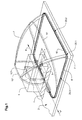
- FIG. 1 shows an exemplary apparatus for strapping by means of loop formation in a waiting position and by means of loop formation by loop reduction and loop guidance by means of an advantageously passive or stationary loop guiding means, as already briefly described above.
- the device has a strapping position 1 (shown as hatched area of a support surface 2).
- a means 3 is arranged, which serves for feeding, retracting and closing the strapping material 4, wherein the strapping material, for example, a polypropylene tape is unwound from a supply roll, not shown, and sealed, for example by welding.
- the strapping material for example, a polypropylene tape is unwound from a supply roll, not shown, and sealed, for example by welding.
- articles 5 to be strapped are fed successively in a feed direction F, strapped and, for example, guided away again in the feed direction F.
- the device further comprises, for example, in the support surface 2 a loop channel 6, the loop of the means 3 for feeding, retracting and closing off and back to this means 3 back and is, for example, substantially rectangular.
- the loop of the means 3 for feeding, retracting and closing off and back to this means 3 back and is, for example, substantially rectangular.
- the two rectangular corners further away from the center 3 are arranged on the directed against the loop inside of the loop channel 6 per a guide rail 7, which bulge substantially transversely to the loop channel 6 and substantially from the support surface 2 against or on the Umreifungsposition 1.
- the loop channel 6 is by inserting and / or pulling the strapping material 4 creates a loop 10.
- the loop 10 by pulling back of the strapping material 4 is reduced, so that the loop, from the guide rails out of the loop channel 6 lifts and straightens.
- the loop 10 is in of Figure 1 pulled out in the waiting position, that is in the loop channel 6, shown and dot-dashed in a partially raised position 10 ', in an upright position Position 10 "and placed in an around the object to be strapped Position 10 "'The upright position 10" is defined by the end of the guide rails 7 and is designed such that from this position, the loop 10th separated by further reduction of the guide rails 7 and substantially can be placed without guidance around the object 5 to be strapped.
- the loop 10 is, for example, in a substantially vertical Level or relative to the support surface or the waiting position relative steep level.
- the device shown in Figure 1 at least an initiation site an active or passive initiating agent, which is in the Loop channel 6 locally created a pulse substantially in the loop direction of a first phase defined by the loop guiding means Loop setup so that the loop 10 at the beginning of the loop reduction begins to erect at this initiation site.
- the figure 1 are three exemplary initiation sites denoted by 20.1, 20.2 and 20.3.
- Active initiators can also be arranged at curved channel locations or in the Regions of rectilinear channel parts (initiation sites 20.2 or 20.3).
- FIG. 1 shows an exemplary embodiment of a device according to the invention can be equipped with an initiator.
- Various Features of the embodiment shown thus do not constitute a condition for the inventive Such features are in particular the feeding and Weg Replacementscardi F, which do not necessarily match and must be aligned parallel to a part of the loop channel 6.
- the position of the means 3 does not necessarily have to be in the center of the strapping position 1 and not necessarily be arranged under the support surface 2.
- the loop channel 6 (waiting position) does not necessarily have to be completely arranged in the support surface 2 and essentially form a flat rectangle. He can also in a contact surface 6 crooked plane lie or form a curved surface and he can Form any polygon with straight or curved sides.
- the loop guide means does not necessarily have to be a plurality of guide rails 7 be designed but can be more flat on a greater length of the loop channel 6 extend. It is also not a condition that the bearing surface 2 is horizontal, so that the term "loop erection" in one of the Gravity independent type must be understood.
- FIGS. 2 to 12 now show exemplary embodiments of active and passive initiating means which can be arranged in the apparatus according to FIG. 1, for example at the initiation sites 20. 1, 20. 2 and / or 20. 3, wherein additional channel curvatures can also be provided at the locations 20 .
- Part of the figures are plan views of the loop plane, a section of sections perpendicular to the loop plane.
- the loop plane is to be understood as a plane in which the loop is created in a substantially flat loop channel, ie for the device according to FIG. 1 essentially the bearing surface 2.
- the loop plane is to be understood as the plane in which the loop channel runs in the vicinity of the initiation site.
- Figures 2 and 3 show a first, exemplary initiating means in the form of a rotary body 30 with a rotation axis 31 which is aligned parallel to the loop plane S and replaces a part of that channel wall which is directed in a channel curvature of the initiation site 20 against the interior of the curve.
- the rotary body 30 is either freely rotatably mounted about the axis of rotation 31 or rotatably driven accordingly.
- Figure 2 shows a plan view of the loop plane S, and on the loop channel 6 and arranged at the Initt istsstelle 20 with channel curvature rotary body 30.
- Figure 3 shows a section (sectional plane III-III in Fig.
- the rotary body 30 is directed against the curvature interior channel wall and optionally arranged over the channel reaching arranged such that the loop 10th is created by the first reduction and that created by this Rotary body 30 passively rotated or an actively driven rotation of the rotating body 30 is triggered. An active rotation of the body can also be triggered simultaneously with the shortening of the strapping material to reduce the Loop.
- the axis of rotation 31 of the rotary body 30 is at a distance arranged from the loop plane S, so that the application of the loop to the Rotary body causes an angular momentum, through which the rotary body 30 in a clockwise direction rotated and thereby the loop 10 is lifted from the loop channel 6.
- the rotary body 30 may additionally have teeth 32, through which a slip the loop is prevented in a direction opposite to the rotation.
- a rotary body 30 with a rotation axis can also be an actively driven Circulation system with at least two deflection means (two parallel to the Loop plane aligned rotation axes) are provided.
- An active rotation of the rotating body 30 can be initiated, for example a measuring signal due to the effect (pressure, torque) of the decreasing Loop on the rotary body 30 or the axis of rotation 31 is generated or by an optical signal transmitter, which controls the movement of the loop 10 from position 10.1 monitored in the position 10.2.
- the active rotation of the rotating body 30 can also simultaneously with the retraction of the strapping material for loop reduction be initiated or delayed by a small amount of time.
- At least one passive rotary body 30 is in such a Arrange curvature in which a guide rail 7 (dash-dotted lines shown) to the rotary body 30, so if appropriate from the loop channel 6 accordingly spaced, can connect.
- the straightening loop becomes in one such trap at the initiation site from the initiator to the guide rail 7 handed over.
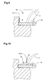
- FIGS. 4 to 6 show another exemplary passive initiating means for a device according to the invention.
- FIGS. 4 and 5 again show a plan view of a curved point of the loop channel 6, which is equipped as an initiation point 20.
- FIG. 6 shows a section as in FIG. 3.
- the initiating means is designed as a slide 40, which in turn replaces a region of the channel wall facing the inside of the bend and through which an opening 41 arranged in the channel bottom can be closed.
- the opening 41 connects to a compressed air source, not shown.
- the slider 40 is perpendicular to the channel length, that is, in the direction in which the decreasing loop 10 acts on him, displaceable against a return spring 42, wherein the opening 41 is opened by such Veschiebung and the strapping material through the effluent from the opening 41 4 and 4: loop in position 10.1, opening 41 closed, Figure 5: loop in position 10.2 after first reduction of the loop, opening 41 opened).
- a slider 40 as shown in Figures 4 to 6, are operated by the decreasing loop 10, for which the slider is to be arranged in a channel curvature.
- the slider 40 can also, as shown in FIG. 7 , be driven by its own drive 43, wherein the drive 43 is activated, for example, by the signal of a sensor 44 monitoring the movement of the loop 10.
- the slider drive may also be activated with the start of loop reduction (along with the activation of the strap retraction means) or with a corresponding predetermined delay thereto.
- Such an actively driven slide can be arranged in a channel curvature or in the region of a substantially straight channel piece.
- FIGS. 8 to 10 show a further, active initiating agent for a device according to the invention, which in turn is arranged in a curved channel location equipped as an initiation site.
- 9 shows the initiation point as a plan view of the loop plane, FIGS. 9 and 10 as a section perpendicular to the loop plane (FIG. 9: loop in the creation position 10.1; FIG. 10: loop in position 10.2 after first loop reduction).
- the initiating means has a guide wheel 51, which in a channel curvature is arranged such that a part of its one end face part of the channel bottom forms and that it is actively rotatable about a rotation axis.
- the axis of rotation is aligned perpendicular to the loop plane and positioned on the inside of the bend.
- On the end of the channel forming the face wheel carries at least a portion of its circumference a gate area 52, in which the distance between the end of the guide wheel replacing the channel bottom and the opposite one Front side enlarged in the direction of rotation, when turning the guide wheel the channel floor formed by this so increases.
- a central Area of the guide wheel 51 connects a guide rail 7 to this.
- the sliding wheel according to FIGS. 8 to 10 is at the beginning of the loop reduction positioned so that the link area 52 in the direction of rotation behind the initiation site lies (Figure 9).
- the rotation of the guide wheel is, for example, with the loop reduction activated and the backdrop area thereby under the strapping material moved, so that this through the gate area of the Loop channel 6 is lifted or raised in the loop channel and by that gained impulse with an initial speed on the guide rail is transmitted (Figure 10).
- link wheel 51 may also be a passively rotatable Be used, which is arranged the same, as shown in Figures 8 to 10 is shown for the guide wheel 51, and its end wall forming the channel bottom is formed cone-shaped.
- the strapping material displaces the passively rotatable Bevel gear when retracting into a rotary motion, causing his ascension is facilitated over the conical surface.
- Figures 11 and 12 show a final example of a passive initiator for a device according to the invention.
- Figure 11 shows a plan view of the whole, substantially rectangular loop channel 6 with the means 3 for feeding, retracting and closing the strapping material and two guide rails 7 and 7 ', wherein the channel curvature is equipped at the base of the guide rail 7 as the initiation point 20.
- Figure 12 shows a section perpendicular to the dish plane in the initiation site.
- the initiator consists essentially of a widening 60 of the loop channel 6 and one in a shallow curvature of the channel widening 60 leading Channel wall 61, which is directed against the curvature interior and the advantageously up above the loop plane (or bearing surface 2) rises and optionally in the beginning of the channel guide rail 7 opens.
- a first loop reduction is the strapping material from the outside of the Channel widening 60 pulled against the channel wall 61 and thereby already has one relevant initial velocity across the length of the strapping material, when the looping up through the gradually rising from the loop channel 6 Channel wall 61 begins.
- the initial speed of the strapping material is the greater, the narrower the channel curvature in the initiation site 20 and ever greater is the channel widening 60.
- All, in particular passive, initiators can attack against the polygon interior extending channel curvatures (e.g., initiation site 20.5).
- the decreasing Do not loop against the channel wall directed inward relative to the loop polygon is driven, but against the inside relative to the curvature, the is called the relative to the loop polygon directed outward channel wall driven so that the ionization means driven by the loop reduction in the Region of this channel outer wall is to be arranged or replaced accordingly.
Landscapes
- Engineering & Computer Science (AREA)
- Mechanical Engineering (AREA)
- Basic Packing Technique (AREA)
- Containers And Plastic Fillers For Packaging (AREA)
Abstract
Description
- Figur 1
- eine dreidimensionale Darstellung einer Vorrichtung zum Umreifen mit Schleifenerstellung in einer Warteposition und Schleifenaufrichtung mittels Schleifenführung und Schleifenverkleinerung;
- Figuren 2 und 3
- ein erstes beispielhaftes passiv oder aktiv betreibbares Initiierungsmittel (Figur 2: Draufsicht auf die Schleifenebene, Figur 3: Schnitt senkrecht zur Schleifenebene);
- Figuren 4 bis 6
- ein weiteres beispielhaftes, passives Initiierungsmittel (Figuren 4 und 5: Draufsicht auf die Schleifenebene, Figur 6: Schnitt senkrecht zur Schleifenebene);
- Figur 7
- ein Initiierungsmittel, das gleich wirkt wie das Inittierungsmittel gemäss Figuren 4 bis 6, das aber aktiv angetrieben ist;
- Figuren 8 bis 10
- ein weiteres beispielhaftes, aktives Initiierungsmittel (Figur 8: Draufsicht auf die Schleifenebene, Figuren 9 und 10: Schnitt senkrecht zur Schleifenebene);
- Figuren 11 und 12
- ein weiteres beispielhaftes, passives Initiierungsmittel (Figur 11: Draufsicht auf die Schleifenebene, Figur 12: Schnitt senkrecht zur Schleifenebene).
Claims (12)
- Vorrichtung zum Umreifen von Gegenständen (5) mit einem Umreifungsmaterial (4), welche Vorrichtung Mittel aufweist, um die Gegenstände (5) nacheinander in einer Zuführungsrichtung (F) in eine Umreifungsposition (1) zuzuführen, in der Umreifungsposition zu positionieren und aus der Umreifungsposition (1) wegzuführen, sowie einen in einer Warteposition angeordneten Schleifenkanal (6) zur Erstellung einer Schleife (10) aus dem Umreifungsmaterial (4), ein Mittel zum Zuführen, Zurückziehen und Verschliessen des Umreifungsmaterials (4) und ein Schleifenführungsmittel, das derart ausgestaltet ist, dass die im Schleifenkanal (6) erstellte Schleife (10) durch eine Schleifenverkleinerung aus mindestens einem Teil des Schleifenkanals (6) hinaus in eine aufgerichtete Position bewegt wird und dabei vom Schleifenführungsmittel geführt wird, dadurch gekennzeichnet, dass die Vorrichtung ferner an mindestens einer Initiierungsstelle (20, 20.1 bis 20.5) ein Intiierungsmittel aufweist, das ausgerüstet ist, um einem in der Initiierungsstelle positionierten Bereich der im Schleifenkanal (6) erstellten Schleife (10) zu Beginn der Schleifenverkleinerung einen Impuls zu geben, der quer zur Länge des Umreifungsmaterials und aus einer Schleifenebene (S) hinaus gerichtet ist.
- Vorrichtung nach Anspruch 1, dadurch gekennzeichnet, dass der Schleifenkanal (6) im wesentlichen die Form eines Polygons mit abgerundeten Ecken aufweist und dass die Schleifenführungsmittel an Polygonecken auf der gegen das Innere des Polygons gerichteten Seite des Schleifenkanals (6) angeordnete Führungsschienen (7) sind.
- Vorrichtung nach Anspruch 2, dadurch gekennzeichnet, dass die Führungsschienen (7) seitlich an den Führungskanal (6) oder von diesem beabstandet an das Initiierungsmittel anschliessen.
- Vorrichtung nach Anspruch 3, dadurch gekennzeichnet, dass die Initiierungsstelle (20, 20.1) in einer Ecke des Polygons angeordnet ist und eine Führungsschiene (7) an das Initiierungsmittel anschliesst, wobei das Initiierungsmittel derart ausgerüstet ist, dass der durch das Initiierungsmittel an den Schleifenbereich übertragene Impuls im wesentlichen einer durch die Führungsschiene (7) definierten Richtung der Schleifenaufrichtung entspricht.
- Vorrichtung nach Anspruch 2, dadurch gekennzeichnet, dass die Initiierungsstelle (20.2, 20.3, 20.4, 20.5) zwischen zwei Ecken des Polygons angeordnet ist, wobei der Schleifenkanal (6) an der Initiierungsstelle (20.2, 20.3) gerade ist oder an der Initiierungsstelle (20.4, 20.5) eine aus dem Polygon hinaus oder gegen das Innere des Polygons verlaufende Krümmung aufweist.
- Vorrichtung nach einem der Ansprüche 1 bis 5, dadurch gekennzeichnet, dass die Initiierungsstelle im Bereich einer Kanalkrümmung angeordnet ist, dass das Initiierungsmittel im Bereich einer gegen das Krümmungsinnere gerichteten Kanalwand angeordnet ist und dass das Initiierungsmittel durch die Schleifenverkleinerung betreibar ist oder einen eigenen Antrieb (43) aufweist.
- Vorrichtung nach einem der Ansprüche 1 bis 5, dadurch gekennzeichnet, dass die Initiierungsstelle im Bereich eines geraden Kanalstücks angeordnet ist und dass das Initiierungsmittel durch einen eigenen Antrieb (43) antreibbar ist.
- Vorrichtung nach Anspruch 6 oder 7, dadurch gekennzeichnet, dass der eigene Antrieb durch die Schleifenverkleinerung aktiviert wird, wobei für die Aktivierung des Antriebs eine Überwachung der Schleifenverkleinerung an der Initiierungsstelle oder eine Koppelung mit der Aktivierung der Schleifenverkleinerung gegbenenfalls mit einer vorgegebenen Verzögerung vorgesehen ist.
- Vorrichtung nach einem der Ansprüche 6 bis 8, dadurch gekennzeichnet, dass das Initiierungsmittel einen Drehkörper (30) mit parallel zur Schleifenebene (S) ausgerichteter Rotationsachse (31) aufweist.
- Vorrichtung nach einem der Ansprüche 6 bis 8, dadurch gekennzeichnet, dass das Initiierungsmittel einen Schieber (40) aufweist, der parallel zur Schleifenebene (S) und quer zum Schleifenkanal (6) verschiebbar ist, sowie eine in einen Kanalboden mündende Öffnung (41), die an eine Druckluftquelle angeschlossen ist und die durch den Schieber (40) geschlossen gehalten wird und durch die Verschiebung des Schiebers (40) geöffnet wird.
- Vorrichtung nach einem der Ansprüche 6 bis 8, dadurch gekennzeichnet, dass das Initiierungsmittel ein Kulissenrad (51) aufweist, das derart angeordnet ist, dass ein Teil seiner einen Stirnseite an der Initiierungsstelle einen Kanalboden bildet und dass das Kulissenrad um eine senkrecht zur Schleifenebene (S) ausgerichtete Rotationsaches drehbar ist, wobei das Kulissenrad (51) auf der genannten Stirnseite einen Kulissenbereich (52) aufweist, durch den bei Drehung des Kulissenrades (51) ein im Schleifenkanal (6) positionierter Schleifenbereich aus dem Schleifenkanal (6) hebbar oder im Schleifenkanal anhebbar ist.
- Vorrichtung nach Anspruch 6, dadurch gekennzeichnet, dass das Initiierungsmittel eine Kanalverbreiterung (60) und eine sich flach aus der Kanalverbreiterung (60) erhebende, gegen das Krümmungsinnere gewandte und die Schleifenebene (S) übersteigende Kanalwand (61) aufweist.
Applications Claiming Priority (2)
| Application Number | Priority Date | Filing Date | Title |
|---|---|---|---|
| CH21032003 | 2003-12-10 | ||
| CH21032003 | 2003-12-10 |
Publications (2)
| Publication Number | Publication Date |
|---|---|
| EP1541472A1 true EP1541472A1 (de) | 2005-06-15 |
| EP1541472B1 EP1541472B1 (de) | 2007-03-14 |
Family
ID=34468807
Family Applications (1)
| Application Number | Title | Priority Date | Filing Date |
|---|---|---|---|
| EP04405753A Expired - Lifetime EP1541472B1 (de) | 2003-12-10 | 2004-12-06 | Vorrichtung zum Umreifen von Gegenständen |
Country Status (4)
| Country | Link |
|---|---|
| EP (1) | EP1541472B1 (de) |
| AT (1) | ATE356749T1 (de) |
| DE (1) | DE502004003202D1 (de) |
| DK (1) | DK1541472T3 (de) |
Citations (3)
| Publication number | Priority date | Publication date | Assignee | Title |
|---|---|---|---|---|
| US3977314A (en) * | 1973-05-24 | 1976-08-31 | Fuji Jidoki Kabushiki Kaisha | Tying device |
| US5078057A (en) * | 1990-01-05 | 1992-01-07 | Illinois Tool Works Inc. | Binding machine, such as strapping machine |
| EP1207107A1 (de) * | 2000-11-20 | 2002-05-22 | Ferag AG | Umreifungsvorrichtung |
-
2004
- 2004-12-06 DK DK04405753T patent/DK1541472T3/da active
- 2004-12-06 AT AT04405753T patent/ATE356749T1/de not_active IP Right Cessation
- 2004-12-06 EP EP04405753A patent/EP1541472B1/de not_active Expired - Lifetime
- 2004-12-06 DE DE502004003202T patent/DE502004003202D1/de not_active Expired - Lifetime
Patent Citations (3)
| Publication number | Priority date | Publication date | Assignee | Title |
|---|---|---|---|---|
| US3977314A (en) * | 1973-05-24 | 1976-08-31 | Fuji Jidoki Kabushiki Kaisha | Tying device |
| US5078057A (en) * | 1990-01-05 | 1992-01-07 | Illinois Tool Works Inc. | Binding machine, such as strapping machine |
| EP1207107A1 (de) * | 2000-11-20 | 2002-05-22 | Ferag AG | Umreifungsvorrichtung |
Also Published As
| Publication number | Publication date |
|---|---|
| ATE356749T1 (de) | 2007-04-15 |
| EP1541472B1 (de) | 2007-03-14 |
| DE502004003202D1 (de) | 2007-04-26 |
| DK1541472T3 (da) | 2007-07-23 |
Similar Documents
| Publication | Publication Date | Title |
|---|---|---|
| DE69015497T2 (de) | Verfahren und Maschine zum Banderolieren einer palettisierten Ladung. | |
| EP3119636B1 (de) | Stromabnehmersystem mit teleskoparm für krane, containerkrane, ertgs und fördereinrichtungen | |
| DE1945126C3 (de) | Vorrichtung zum Formen von Behältern | |
| DE2250667A1 (de) | Vorrichtung zum aufrichten von flachgefalteten verpackungskartons | |
| DE2928641C2 (de) | Vorrichtung zum Ausbreiten und Führen einer Wirkwarenbahn | |
| DE2353851A1 (de) | Verfahren und einrichtung zur handhabung stabfoermiger gegenstaende | |
| EP3006197A1 (de) | Vorrichtung und verfahren zum aufrichten vorwiegend flächiger materialzuschnitte | |
| DE2942883C2 (de) | Vorrichtung zum Verschließen des Bodens einer rechteckigen aufgerichteten Faltschachtel | |
| DE3003586C2 (de) | ||
| DE2203846A1 (de) | Energieaufnehmende Einrichtung | |
| DE2231321A1 (de) | Maschine fuer das anbringen von klebeband zum verschliessen prismatischer schachteln in verschiedener groesse | |
| DE9002694U1 (de) | Vorrichtung zum Schließen einer mit zumindest einer Lasche versehenen Verpackung | |
| DE1913188C3 (de) | Vorrichtung zum Offnen von FaIt schachteln bzw Faltkartons und zum Her anfuhren derselben an das Mundstuck einer automatischen Abfüllmaschine | |
| EP1541472B1 (de) | Vorrichtung zum Umreifen von Gegenständen | |
| DE2703946C2 (de) | Tiefziehvorrichtung zum Herstellen von je mit einer Banderole versehenen Behältern aus thermoplastischem Kunststoff | |
| DE1940426C3 (de) | Steuervorrichtung fur eine Band haspelanlage | |
| DE1912895C3 (de) | Vorrichtung zum Aufsetzen von mit jeweils einem Ventil versehenen Deckeln auf Aerosolbehälter | |
| DE2229289A1 (de) | Antriebssystem fuer regelstaebe | |
| DE2112881B2 (de) | Verfahren zum abstreifen eines duennwandigen, becherfoermigen behaelters von einem stempel einer ziehpresse | |
| EP2201849A1 (de) | Aufwickelvorrichtung für flache, wickelfähige Lebensmittel | |
| DE69402500T2 (de) | Automatische Abgabevorrichtung für Gegenstände | |
| DE10114044B4 (de) | Vorrichtung zum Führen eines in eine Transporteinrichtung einzulegenden Körpers | |
| DE19652448C9 (de) | Vorrichtung zum Verpacken einer Materialbahnrolle mit einer Verpackungsbahn | |
| DE4004817C2 (de) | Vorrichtung zum Schließen des Ventils eines mittels einer Füllmaschine gefüllten Ventilsackes | |
| DE3442943A1 (de) | Vorrichtung zum falten der oeffnung von gefuellten saecken |
Legal Events
| Date | Code | Title | Description |
|---|---|---|---|
| PUAI | Public reference made under article 153(3) epc to a published international application that has entered the european phase |
Free format text: ORIGINAL CODE: 0009012 |
|
| AK | Designated contracting states |
Kind code of ref document: A1 Designated state(s): AT BE BG CH CY CZ DE DK EE ES FI FR GB GR HU IE IS IT LI LT LU MC NL PL PT RO SE SI SK TR |
|
| AX | Request for extension of the european patent |
Extension state: AL BA HR LV MK YU |
|
| 17P | Request for examination filed |
Effective date: 20050603 |
|
| AKX | Designation fees paid |
Designated state(s): AT BE BG CH CY CZ DE DK EE ES FI FR GB GR HU IE IS IT LI LT LU MC NL PL PT RO SE SI SK TR |
|
| GRAP | Despatch of communication of intention to grant a patent |
Free format text: ORIGINAL CODE: EPIDOSNIGR1 |
|
| GRAS | Grant fee paid |
Free format text: ORIGINAL CODE: EPIDOSNIGR3 |
|
| GRAA | (expected) grant |
Free format text: ORIGINAL CODE: 0009210 |
|
| AK | Designated contracting states |
Kind code of ref document: B1 Designated state(s): AT BE BG CH CY CZ DE DK EE ES FI FR GB GR HU IE IS IT LI LT LU MC NL PL PT RO SE SI SK TR |
|
| PG25 | Lapsed in a contracting state [announced via postgrant information from national office to epo] |
Ref country code: FI Free format text: LAPSE BECAUSE OF FAILURE TO SUBMIT A TRANSLATION OF THE DESCRIPTION OR TO PAY THE FEE WITHIN THE PRESCRIBED TIME-LIMIT Effective date: 20070314 Ref country code: NL Free format text: LAPSE BECAUSE OF FAILURE TO SUBMIT A TRANSLATION OF THE DESCRIPTION OR TO PAY THE FEE WITHIN THE PRESCRIBED TIME-LIMIT Effective date: 20070314 Ref country code: PL Free format text: LAPSE BECAUSE OF FAILURE TO SUBMIT A TRANSLATION OF THE DESCRIPTION OR TO PAY THE FEE WITHIN THE PRESCRIBED TIME-LIMIT Effective date: 20070314 Ref country code: SI Free format text: LAPSE BECAUSE OF FAILURE TO SUBMIT A TRANSLATION OF THE DESCRIPTION OR TO PAY THE FEE WITHIN THE PRESCRIBED TIME-LIMIT Effective date: 20070314 |
|
| REG | Reference to a national code |
Ref country code: GB Ref legal event code: FG4D Free format text: NOT ENGLISH |
|
| REG | Reference to a national code |
Ref country code: CH Ref legal event code: EP |
|
| REF | Corresponds to: |
Ref document number: 502004003202 Country of ref document: DE Date of ref document: 20070426 Kind code of ref document: P |
|
| REG | Reference to a national code |
Ref country code: IE Ref legal event code: FG4D Free format text: LANGUAGE OF EP DOCUMENT: GERMAN |
|
| REG | Reference to a national code |
Ref country code: CH Ref legal event code: NV Representative=s name: FREI PATENTANWALTSBUERO AG |
|
| GBT | Gb: translation of ep patent filed (gb section 77(6)(a)/1977) |
Effective date: 20070523 |
|
| PG25 | Lapsed in a contracting state [announced via postgrant information from national office to epo] |
Ref country code: ES Free format text: LAPSE BECAUSE OF FAILURE TO SUBMIT A TRANSLATION OF THE DESCRIPTION OR TO PAY THE FEE WITHIN THE PRESCRIBED TIME-LIMIT Effective date: 20070625 |
|
| REG | Reference to a national code |
Ref country code: SE Ref legal event code: TRGR |
|
| PG25 | Lapsed in a contracting state [announced via postgrant information from national office to epo] |
Ref country code: IS Free format text: LAPSE BECAUSE OF FAILURE TO SUBMIT A TRANSLATION OF THE DESCRIPTION OR TO PAY THE FEE WITHIN THE PRESCRIBED TIME-LIMIT Effective date: 20070714 |
|
| REG | Reference to a national code |
Ref country code: DK Ref legal event code: T3 |
|
| PG25 | Lapsed in a contracting state [announced via postgrant information from national office to epo] |
Ref country code: PT Free format text: LAPSE BECAUSE OF FAILURE TO SUBMIT A TRANSLATION OF THE DESCRIPTION OR TO PAY THE FEE WITHIN THE PRESCRIBED TIME-LIMIT Effective date: 20070814 |
|
| NLV1 | Nl: lapsed or annulled due to failure to fulfill the requirements of art. 29p and 29m of the patents act | ||
| EN | Fr: translation not filed | ||
| EN | Fr: translation not filed | ||
| PG25 | Lapsed in a contracting state [announced via postgrant information from national office to epo] |
Ref country code: SK Free format text: LAPSE BECAUSE OF FAILURE TO SUBMIT A TRANSLATION OF THE DESCRIPTION OR TO PAY THE FEE WITHIN THE PRESCRIBED TIME-LIMIT Effective date: 20070314 |
|
| REG | Reference to a national code |
Ref country code: IE Ref legal event code: FD4D |
|
| PG25 | Lapsed in a contracting state [announced via postgrant information from national office to epo] |
Ref country code: RO Free format text: LAPSE BECAUSE OF FAILURE TO SUBMIT A TRANSLATION OF THE DESCRIPTION OR TO PAY THE FEE WITHIN THE PRESCRIBED TIME-LIMIT Effective date: 20070314 Ref country code: CZ Free format text: LAPSE BECAUSE OF FAILURE TO SUBMIT A TRANSLATION OF THE DESCRIPTION OR TO PAY THE FEE WITHIN THE PRESCRIBED TIME-LIMIT Effective date: 20070314 |
|
| PLBE | No opposition filed within time limit |
Free format text: ORIGINAL CODE: 0009261 |
|
| STAA | Information on the status of an ep patent application or granted ep patent |
Free format text: STATUS: NO OPPOSITION FILED WITHIN TIME LIMIT |
|
| PG25 | Lapsed in a contracting state [announced via postgrant information from national office to epo] |
Ref country code: IE Free format text: LAPSE BECAUSE OF FAILURE TO SUBMIT A TRANSLATION OF THE DESCRIPTION OR TO PAY THE FEE WITHIN THE PRESCRIBED TIME-LIMIT Effective date: 20070314 |
|
| PGFP | Annual fee paid to national office [announced via postgrant information from national office to epo] |
Ref country code: DK Payment date: 20071214 Year of fee payment: 4 |
|
| 26N | No opposition filed |
Effective date: 20071217 |
|
| PGFP | Annual fee paid to national office [announced via postgrant information from national office to epo] |
Ref country code: AT Payment date: 20071224 Year of fee payment: 4 |
|
| PG25 | Lapsed in a contracting state [announced via postgrant information from national office to epo] |
Ref country code: LT Free format text: LAPSE BECAUSE OF FAILURE TO SUBMIT A TRANSLATION OF THE DESCRIPTION OR TO PAY THE FEE WITHIN THE PRESCRIBED TIME-LIMIT Effective date: 20070314 |
|
| PGFP | Annual fee paid to national office [announced via postgrant information from national office to epo] |
Ref country code: SE Payment date: 20071213 Year of fee payment: 4 |
|
| PG25 | Lapsed in a contracting state [announced via postgrant information from national office to epo] |
Ref country code: FR Free format text: LAPSE BECAUSE OF FAILURE TO SUBMIT A TRANSLATION OF THE DESCRIPTION OR TO PAY THE FEE WITHIN THE PRESCRIBED TIME-LIMIT Effective date: 20071102 Ref country code: GR Free format text: LAPSE BECAUSE OF FAILURE TO SUBMIT A TRANSLATION OF THE DESCRIPTION OR TO PAY THE FEE WITHIN THE PRESCRIBED TIME-LIMIT Effective date: 20070615 |
|
| BERE | Be: lapsed |
Owner name: FERAG AG Effective date: 20071231 |
|
| PG25 | Lapsed in a contracting state [announced via postgrant information from national office to epo] |
Ref country code: MC Free format text: LAPSE BECAUSE OF NON-PAYMENT OF DUE FEES Effective date: 20071231 |
|
| PG25 | Lapsed in a contracting state [announced via postgrant information from national office to epo] |
Ref country code: BE Free format text: LAPSE BECAUSE OF NON-PAYMENT OF DUE FEES Effective date: 20071231 |
|
| PG25 | Lapsed in a contracting state [announced via postgrant information from national office to epo] |
Ref country code: FR Free format text: LAPSE BECAUSE OF FAILURE TO SUBMIT A TRANSLATION OF THE DESCRIPTION OR TO PAY THE FEE WITHIN THE PRESCRIBED TIME-LIMIT Effective date: 20070314 |
|
| PG25 | Lapsed in a contracting state [announced via postgrant information from national office to epo] |
Ref country code: EE Free format text: LAPSE BECAUSE OF FAILURE TO SUBMIT A TRANSLATION OF THE DESCRIPTION OR TO PAY THE FEE WITHIN THE PRESCRIBED TIME-LIMIT Effective date: 20070314 |
|
| PG25 | Lapsed in a contracting state [announced via postgrant information from national office to epo] |
Ref country code: CY Free format text: LAPSE BECAUSE OF FAILURE TO SUBMIT A TRANSLATION OF THE DESCRIPTION OR TO PAY THE FEE WITHIN THE PRESCRIBED TIME-LIMIT Effective date: 20070314 |
|
| REG | Reference to a national code |
Ref country code: DK Ref legal event code: EBP |
|
| EUG | Se: european patent has lapsed | ||
| GBPC | Gb: european patent ceased through non-payment of renewal fee |
Effective date: 20081206 |
|
| PG25 | Lapsed in a contracting state [announced via postgrant information from national office to epo] |
Ref country code: AT Free format text: LAPSE BECAUSE OF NON-PAYMENT OF DUE FEES Effective date: 20081206 Ref country code: LU Free format text: LAPSE BECAUSE OF NON-PAYMENT OF DUE FEES Effective date: 20071206 Ref country code: BG Free format text: LAPSE BECAUSE OF FAILURE TO SUBMIT A TRANSLATION OF THE DESCRIPTION OR TO PAY THE FEE WITHIN THE PRESCRIBED TIME-LIMIT Effective date: 20070614 |
|
| PG25 | Lapsed in a contracting state [announced via postgrant information from national office to epo] |
Ref country code: HU Free format text: LAPSE BECAUSE OF FAILURE TO SUBMIT A TRANSLATION OF THE DESCRIPTION OR TO PAY THE FEE WITHIN THE PRESCRIBED TIME-LIMIT Effective date: 20070915 Ref country code: TR Free format text: LAPSE BECAUSE OF FAILURE TO SUBMIT A TRANSLATION OF THE DESCRIPTION OR TO PAY THE FEE WITHIN THE PRESCRIBED TIME-LIMIT Effective date: 20070314 |
|
| PG25 | Lapsed in a contracting state [announced via postgrant information from national office to epo] |
Ref country code: GB Free format text: LAPSE BECAUSE OF NON-PAYMENT OF DUE FEES Effective date: 20081206 |
|
| PG25 | Lapsed in a contracting state [announced via postgrant information from national office to epo] |
Ref country code: DK Free format text: LAPSE BECAUSE OF NON-PAYMENT OF DUE FEES Effective date: 20090105 |
|
| PGFP | Annual fee paid to national office [announced via postgrant information from national office to epo] |
Ref country code: DE Payment date: 20091222 Year of fee payment: 6 |
|
| PG25 | Lapsed in a contracting state [announced via postgrant information from national office to epo] |
Ref country code: SE Free format text: LAPSE BECAUSE OF NON-PAYMENT OF DUE FEES Effective date: 20081207 |
|
| PGFP | Annual fee paid to national office [announced via postgrant information from national office to epo] |
Ref country code: CH Payment date: 20101222 Year of fee payment: 7 |
|
| REG | Reference to a national code |
Ref country code: DE Ref legal event code: R119 Ref document number: 502004003202 Country of ref document: DE Effective date: 20110701 |
|
| PG25 | Lapsed in a contracting state [announced via postgrant information from national office to epo] |
Ref country code: DE Free format text: LAPSE BECAUSE OF NON-PAYMENT OF DUE FEES Effective date: 20110701 |
|
| PGFP | Annual fee paid to national office [announced via postgrant information from national office to epo] |
Ref country code: IT Payment date: 20071231 Year of fee payment: 4 |
|
| REG | Reference to a national code |
Ref country code: CH Ref legal event code: PL |
|
| PG25 | Lapsed in a contracting state [announced via postgrant information from national office to epo] |
Ref country code: LI Free format text: LAPSE BECAUSE OF NON-PAYMENT OF DUE FEES Effective date: 20111231 Ref country code: CH Free format text: LAPSE BECAUSE OF NON-PAYMENT OF DUE FEES Effective date: 20111231 |