EP1539584B1 - Verflechtungsanlage und mit dergleicher anlage versehene palettisiervorrichtung - Google Patents
Verflechtungsanlage und mit dergleicher anlage versehene palettisiervorrichtung Download PDFInfo
- Publication number
- EP1539584B1 EP1539584B1 EP03755647A EP03755647A EP1539584B1 EP 1539584 B1 EP1539584 B1 EP 1539584B1 EP 03755647 A EP03755647 A EP 03755647A EP 03755647 A EP03755647 A EP 03755647A EP 1539584 B1 EP1539584 B1 EP 1539584B1
- Authority
- EP
- European Patent Office
- Prior art keywords
- interlacing
- gantry
- products
- tubes
- transport pallet
- Prior art date
- Legal status (The legal status is an assumption and is not a legal conclusion. Google has not performed a legal analysis and makes no representation as to the accuracy of the status listed.)
- Expired - Lifetime
Links
- 238000003860 storage Methods 0.000 claims description 5
- 230000005540 biological transmission Effects 0.000 claims description 4
- 230000003213 activating effect Effects 0.000 claims 4
- 230000037361 pathway Effects 0.000 claims 1
- 230000007246 mechanism Effects 0.000 description 3
- 230000015572 biosynthetic process Effects 0.000 description 2
- 238000003780 insertion Methods 0.000 description 2
- 230000037431 insertion Effects 0.000 description 2
- 238000004519 manufacturing process Methods 0.000 description 2
- 238000005096 rolling process Methods 0.000 description 2
- 238000009825 accumulation Methods 0.000 description 1
- 230000008859 change Effects 0.000 description 1
- 210000000078 claw Anatomy 0.000 description 1
- 210000001520 comb Anatomy 0.000 description 1
- 230000001419 dependent effect Effects 0.000 description 1
- 238000006073 displacement reaction Methods 0.000 description 1
- 239000000835 fiber Substances 0.000 description 1
- 238000000034 method Methods 0.000 description 1
- 230000004048 modification Effects 0.000 description 1
- 238000012986 modification Methods 0.000 description 1
- 210000000056 organ Anatomy 0.000 description 1
- 239000002985 plastic film Substances 0.000 description 1
- 229920006255 plastic film Polymers 0.000 description 1
- 238000007747 plating Methods 0.000 description 1
- 230000008569 process Effects 0.000 description 1
- 229920002994 synthetic fiber Polymers 0.000 description 1
- 230000000007 visual effect Effects 0.000 description 1
Images


Classifications
-
- B—PERFORMING OPERATIONS; TRANSPORTING
- B65—CONVEYING; PACKING; STORING; HANDLING THIN OR FILAMENTARY MATERIAL
- B65G—TRANSPORT OR STORAGE DEVICES, e.g. CONVEYORS FOR LOADING OR TIPPING, SHOP CONVEYOR SYSTEMS OR PNEUMATIC TUBE CONVEYORS
- B65G57/00—Stacking of articles
- B65G57/005—Stacking of articles by using insertions or spacers between the stacked layers
-
- B—PERFORMING OPERATIONS; TRANSPORTING
- B65—CONVEYING; PACKING; STORING; HANDLING THIN OR FILAMENTARY MATERIAL
- B65B—MACHINES, APPARATUS OR DEVICES FOR, OR METHODS OF, PACKAGING ARTICLES OR MATERIALS; UNPACKING
- B65B17/00—Other machines, apparatus, or methods for packaging articles or materials
- B65B17/02—Joining articles, e.g. cans, directly to each other for convenience of storage, transport, or handling
-
- B—PERFORMING OPERATIONS; TRANSPORTING
- B65—CONVEYING; PACKING; STORING; HANDLING THIN OR FILAMENTARY MATERIAL
- B65B—MACHINES, APPARATUS OR DEVICES FOR, OR METHODS OF, PACKAGING ARTICLES OR MATERIALS; UNPACKING
- B65B27/00—Bundling particular articles presenting special problems using string, wire, or narrow tape or band; Baling fibrous material, e.g. peat, not otherwise provided for
- B65B27/10—Bundling rods, sticks, or like elongated objects
-
- B—PERFORMING OPERATIONS; TRANSPORTING
- B65—CONVEYING; PACKING; STORING; HANDLING THIN OR FILAMENTARY MATERIAL
- B65G—TRANSPORT OR STORAGE DEVICES, e.g. CONVEYORS FOR LOADING OR TIPPING, SHOP CONVEYOR SYSTEMS OR PNEUMATIC TUBE CONVEYORS
- B65G57/00—Stacking of articles
- B65G57/02—Stacking of articles by adding to the top of the stack
- B65G57/16—Stacking of articles of particular shape
- B65G57/18—Stacking of articles of particular shape elongated, e.g. sticks, rods, bars
- B65G57/186—Cylindrical articles, e.g. tubes, rods, etc.
-
- B—PERFORMING OPERATIONS; TRANSPORTING
- B65—CONVEYING; PACKING; STORING; HANDLING THIN OR FILAMENTARY MATERIAL
- B65G—TRANSPORT OR STORAGE DEVICES, e.g. CONVEYORS FOR LOADING OR TIPPING, SHOP CONVEYOR SYSTEMS OR PNEUMATIC TUBE CONVEYORS
- B65G2201/00—Indexing codes relating to handling devices, e.g. conveyors, characterised by the type of product or load being conveyed or handled
- B65G2201/02—Articles
- B65G2201/0214—Articles of special size, shape or weigh
- B65G2201/0217—Elongated
-
- B—PERFORMING OPERATIONS; TRANSPORTING
- B65—CONVEYING; PACKING; STORING; HANDLING THIN OR FILAMENTARY MATERIAL
- B65G—TRANSPORT OR STORAGE DEVICES, e.g. CONVEYORS FOR LOADING OR TIPPING, SHOP CONVEYOR SYSTEMS OR PNEUMATIC TUBE CONVEYORS
- B65G2201/00—Indexing codes relating to handling devices, e.g. conveyors, characterised by the type of product or load being conveyed or handled
- B65G2201/02—Articles
- B65G2201/0276—Tubes and pipes
Definitions
- the present invention relates to a device for interlacing machine for palletizing elongated products and a palletizing machine equipped with such a device, this palletizing machine comprising at least one gantry, a carriage mounted movably in vertical translation on said gantry and a gripping device movable in horizontal translation on said carriage and arranged to take said products from a storage ramp and deposit them on a pallet transport.
- This type of palletizing machine is well known for palletizing, automatically or semi-automatically, elongated products, for example cylindrical tubes, directly and continuously at the output of their production line.
- the palletizing of the tubes is a delicate operation since, when they are deposited side by side and in superposed layers, they tend to roll over each other.
- This disadvantage is remedied by interleaving the rows of tubes by means of a link, which may be a string, a ribbon, a braid, a band, a width, a film or any other equivalent means, in fibers, threads , natural and / or synthetic materials, this bond being woven, non-woven, extruded or otherwise obtained, the purpose of this tie being to maintain the rows together and to prevent the tubes from dropping before strapping the pallet .
- This interlacing is usually performed manually by an operator who must move the link coil or coils from one side to the other of the pallet according to the advancement of the rows. If the tubes are very long, they can reach up to 10 meters in length, the number of interlacing coils must be at least doubled, which mobilizes more than one operator.
- WO 02/06121 of the same holder describes a palletizing machine equipped with an interlacing device for automatically interlacing the tubes during their palletizing.
- This interlacing device comprises two supports arranged on either side of the transport pallet and arranged to receive alternately one or more intertwining link coils.
- This device also comprises gripping means mounted on the gripping device of the tubes or on an additional gripping device and arranged to move the interlacing coil or bobbins from one support to the other as a function of the progress of the rows of tubes deposited on the pallet of transport.
- This interlacing device being integral with the palletizing machine does not provide an optimal industrial solution.
- the gripping means are embedded on the gripping device of the tubes, it is necessary to interrupt the palletizing cycle to move the interlace interlacing coil from one carrier to the other, which penalizes the overall performance of the palletizing machine. If the gripping means are embedded on an additional gripping device to the tube gripping device, the interlacing device becomes complex to achieve, which penalizes the overall cost of the palletizing machine.
- Publication US-A-5,769,601 proposes an interlacing device integrated in a palletizing machine whose operation is reversed to that of the invention.
- the tubes are brought to the top of the machine by a conveyor and placed on a pallet by pushing cylinders to form a row. After each row, the pallet moves down one level to allow the formation of a new row.
- An interlacing reel movable in translation perpendicular to said tubes unrolls a strip of paper or plastic film between the rows of tubes to maintain them.
- This interlacing device is not transferable to the palletizing machine of the invention and does not allow the interlacing of tubes of great length.
- the object of the present invention is to overcome these disadvantages by providing an economic interlacing device, able to operate in masked time with respect to the palletizing machine to not penalize its performance and may be suitable for any length of tubes.
- an interlacing device as defined in the preamble and characterized in that it comprises at least one interlacing gantry intended to extend substantially parallel to said products over at least a part of their length, this gantry interlacing device comprising at least one guide fed by at least one interlacing link coil, said interleaving device also comprising drive means coupled to said interleaving gantry for moving it alternately between at least two extreme positions so as to moving said guide in at least one interlacing plane substantially perpendicular to said palletized products alternately from one side to the other of said pallet transport.
- the drive means may be arranged to animate the interlacing gantry of at least one reciprocating pivot movement and / or at least one alternative translational movement.
- the drive means may be selected from the group comprising at least electric motors, hydraulic cylinders and pneumatic. Depending on the drive means selected, they may also comprise at least one transmission system selected from the group comprising at least the pinions and chain, the pulleys and belt.
- the interlacing device comprises at least one frame incorporating means for guiding said interlacing gantry in translation, these guide means possibly comprising at least one raceway formed in the chassis for receiving organs. integral with the uprights of said interlacing gantry.
- the interlacing device comprises at least two guides arranged on the interlacing gantry to distribute at least two interlacing links in at least two interleaving planes substantially parallel and distributed along the length of said palletized products.
- At least one of the guides is associated with actuating means arranged to move it in alternative translation along said interlacing gantry over a predetermined distance to move said corresponding interlacing plane substantially parallel to it.
- the actuating means may be selected from the group comprising at least the electric motors, the hydraulic cylinders and pneumatic.
- a palletizing machine as defined in the preamble and characterized in that it comprises at least one interlacing device as defined above.
- the interlacing device comprises at least one interlacing gantry having dimensions such that it fits into the gantry of the palletizing machine under the gripping device and to the outside the pallet and palletized products.
- This gripping device advantageously comprises means for controlling its drive means associated with the servo-control means of said palletizing machine in order to move said interlacing gantry alternately from one side to the other of said transport pallet substantially. parallel to the interlacing plans according to the advancement of the removal of the products on said pallet transport and according to a predefined interlacing pattern.
- At least one of the guides of the interlacing device is associated with actuating means arranged to move it in alternative translation along said interlacing gantry for a predetermined distance so as to move said plane of corresponding interlacing substantially parallel to itself.
- control means are arranged to control these actuating means so as to surround said interlacing link around the posts of said pallet according to the progress of the palletizing of the products and the interlacing pattern predefined.
- the interlacing device 10, 10 ' is intended to equip a palletizing machine 1 with elongated products, for example cylindrical tubes 2, the length of which may vary from approximately 1 to 10 meters.
- This palletizing machine 1 is usually, but not necessarily, disposed at the outlet of a continuous manufacturing line of these tubes 2 and allows their automatic or semi-automatic palletizing, according to a continuous or discontinuous process.
- it comprises a gantry 3 on which is mounted a carriage 4 movable in vertical translation.
- At least one grip device 5 with claws, suction cups or any other suitable means, is mounted on this carriage 4 in horizontal translation and is arranged to take the tubes 2 arranged side by side and parallel on an inclined storage ramp 6 and the deposit side by side and parallel on at least one transport pallet 7 or any other fixed or mobile support.
- the gripping device 5 is constituted by a gripping beam 5 extending over the entire length of the tubes 2, this gripping beam 5 being equipped with suction systems 5 'to carry the tubes 2 by suction .
- the transport pallet 7 is carried by a movable carriage 8 but can also be arranged between fixed and / or removable amounts.
- An interlacing device 10 is associated with the palletizing machine 1 and arranged to automatically interleave the rows of tubes 2 on the transport pallet 7 so as to ensure that the tubes are held relative to one another and the rows one against the other.
- this interlacing device 10 comprises at least one interlacing gantry 11 extending substantially parallel to the tubes 2 over all or part of their length and integrating into the bulk of the gantry 3 of the palletizing machine 1.
- the interlacing gantry 11 must be able to move inside the palletizing machine 1 below the gripping beam 5 and perpendicularly to the palletized tubes 2.
- This interlacing gantry 11 consists in particular of two uprights 11a vertical connected in the upper part by a horizontal beam 11b and two gallows 11c. If it is formed of a single part, it extends over the entire length of the tubes 2.
- This interlacing gantry 11 is fed from one or both sides by one or more interlacing coils 12 arranged either in a coil holder housing 13 embarked on the interlacing gantry 11 as in FIG. on the ground as in Figure 1, either on a reel rack (not shown) or on any other mobile or fixed equivalent support.
- This interlacing gantry 11 is arranged to be movable alternately at least in a direction substantially perpendicular to the tubes 2 between at least two extreme positions located substantially on either side of the transport pallet 7.
- This reciprocating movement makes it possible to unwind the coil or coils 12 interlacing 12 'in interleaving planes P substantially parallel to each other and perpendicular to said tubes 2.
- This reciprocating movement may be a pivot around a low point or a translation along a stroke C as in the example shown.
- the interlacing device 10 comprises, for this purpose, a drive mechanism 14 consisting for example of an electric motor 15 and a transmission system by sprockets and chain 16 or pulleys and belt or any other equivalent system .
- the drive mechanism 14 may also be constituted by a hydraulic or pneumatic cylinder system or by any equivalent mechanism.
- the interlacing gantry 11 is guided in translation by appropriate guiding means comprising, for example, rolling members 17, such as rollers, flowing in at least one raceway 18 provided in a frame 19, or any other equivalent means. .
- the rolling members 17 are provided on each vertical upright 11a of the interlacing gantry 11 to ensure good guidance.
- the frame 19 consists, in the example shown, of two elongate, substantially parallel bases 19 ', adjustable in height by feet and distributed at each end of the interlacing gantry 11 to guide each vertical upright 11a.
- a third base 19 ' is provided in a median zone of interlacing gantry 11 for transmitting the driving movement of the electric motor 15 on the other side of the interleaving gantry 11 by a gearbox and transmission shafts, so as to also ensure simultaneous driving of the two vertical uprights 11a of interlacing gantry 11.
- Interlacing gantry 11 also includes guides 20 for guiding and separating interlacing links 12 'from coils 12. Depending on the type of interlacing 12' (wire, tape, sheet, film), these guides 20 are suitable. In the example shown, the interlacing link 12 'is a wire product and the guides 20 are wire guides, this term being used for the remainder of the description. These wire guides 20 may consist for example of detour rollers, eyelets, combs and any other equivalent wire guide, used alone or in combination. These wire guides 20 may be passive or active, that is to say animated by a rotational movement for example for detour rollers.
- the wireguides 20 of the spar 11b are positioned in the interleaving planes P defined for each type and length of tubes 2. For tubes 2 of small lengths, of approximately 1 to 3 meters, the interlacing is carried out in the two end zones. For longer tubes, the interlacing must be performed in the two end zones and in one or two median areas as in the example of FIG. 1.
- the interleaver 10 must be powered by a number of interlacing coil 12 equivalent to the number of interleaving planes P.
- interlacing gantry 11 can be fed from both sides.
- the coils 12 are empty, they must be replaced by full coils 12.
- the end of the reels 12 can be identified in different ways taking into account either its weight or the length of the interlacing link 12 '.
- These data are introduced into the servocontrol means of the interlacing device 10 to trigger a visual and / or auditory end-of-coil signal to warn the operator that he must change the empty coil by a full spool.
- the junction between the end of the coil 12 that ends and the beginning of a new coil 12 can be performed manually or automatically using a gnar or any other equivalent device.
- the interlacing device 10 comprises own or integrated control means to the servo-control means of the palletizing machine 1. In all cases, these servo-control means are dependent on the operation of the palletizing machine 1 so as to moving the interlacing gantry 11 automatically and alternately from one side to the other of the transport pallet 7 as a function of the progress of the rows of tubes 2 deposited on this transport pallet 7 and according to a predefined interlacing pattern an example of which is illustrated in Figure 5.
- FIGS. 4A and 4B The realization of this interlacing pattern is explained with reference to FIGS. 4A and 4B.
- the interlacing gantry 11 is shown in its two extreme positions: its start position in dashed lines and its finish position in solid lines.
- the gripping beam 5 of the tubes 2 is shown in two positions: a high position in solid line and a low position in broken lines.
- This gripping beam 5 comprises three 5 'suction cup systems making it possible to carry a maximum of three tubes 2.
- the interlacing gantry 11 is moved from the left to the right of the transport pallet 7 (see FIG 4B) to deposit the interlacing links 12 'on the pallet 7 leaving their end overflowing to be able to make the knots at the end of palletizing.
- a first row of eight tubes 2 is deposited on the pallet 7 by plating the interlacing link 12 'on the transport pallet 7. This first row can be formed by a first and a second series S1, S2 of three tubes 2 and then a third series S3 of two tubes 2 deposited side by side.
- the interlacing gantry 11 is moved from the right to the left of the transport pallet 7 (see Fig.
- the operator cuts the interlacing link 12 'and then moves the mobile frame 8 to set up another mobile frame 8 in front of the gantry 3 to start a new palletizing cycle.
- the use of a mobile frame 8 reduces the interruption between two palletizing cycles to a few seconds to prevent the accumulation of tubes 2 at the storage ramp 6.
- the operator can then finish to tie the ends interlacing link 12 'so as to evacuate the transport pallet 7 tubes 2 by a stacker or any other means. It is of course possible to automate the evacuation of the mobile carriage 8 full and the supply of a mobile carriage 8 empty.
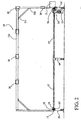
- the interlacing can be improved or reinforced by surrounding the interlacing link 12 'around the posts 7' which extend vertically for example from the four corners of the pallet 7.
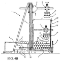
- Figures 6 to 8 illustrate a variant of embodiment of the interlacing device 10 'which makes it possible to perform this type of specific interleaving.
- the wire guides 20 'provided on the interlacing gantry 11' are associated with actuating means 21 arranged to move them in alternative translation AV / AR along this interlacing gantry 11 'on a predetermined path D.
- the actuating means 21 are in the example shown in FIG. hydraulic or pneumatic double-acting cylinders controlled by the servo-control means of the interlacing device 10 'or those of the palletizing machine 1.
- the carriage 1 carrying the gripping device 5 comprises additional parts called pushers 5 "extending vertically and whose function is to lower the interlacing link 12 'along the posts 7'
- These pushers 5" can be fixed or animated with a movement in vertical alternative translation for example to means of cylinders.
- this interlacing device 10 is explained with reference to FIGS. 6 and 7.
- it is chosen to surround the interlacing links 12 around the posts 7 'to secure the tubes 2 to the pallet 7.
- the interlacing gantry 11 ' is moved from the right to the left of the transport pallet 7 of its stroke C to deposit the interlacing links 12' on the pallet 7 while leaving it overflowing their end to be able to perform the nodes at the end of palletizing.
- Four rows of tubes 2 are deposited on the pallet 7 staggered by the gripping device 5.
- the interlacing gantry 11 ' is moved from the left to the right of the transport pallet 7 and the wire guides 20' are moved in translation AR before a series of six tubes 2 is deposited.
- the interlacing gantry 11 ' is brought to the left of the transport pallet 7 and the wire guides 20' are moved in translation AV before a series of six tubes 2 is deposited next to the preceding one to form the fifth row of 2.
- the interlacing gantry 11 ' is moved to the right closing the interlacing link loop 12' formed around the posts 7 'opposite.
- Three other rows of tubes 2 are staggered before the interlacing gantry 11 'moves to the left and the wire guides 20' move in translation AR to form a new loop around the posts 7 '.
- the formation of the stacked rows of tubes 2 combined with the insertion of the interlacing links 12 ' continues as follows until the desired height. The number of rows of course depends on the weight and dimensions of the tubes 2.
- the operator knots the ends of the interlacing link 12 '.
- the interlacing 12 ' is surrounded in a loop around the posts 7' facing. It can of course be surrounded by another drawing and for example in "8".
- the invention makes it possible to achieve the goals set in particular to be able to interleave the rows of tubes 2 as and when they are palletized automatically, optimally and economically.
- the interlacing device 10 according to the invention can be adapted to any length of tubes 2 and any existing automatic palletizing machine 1 operating on the same principle.
Landscapes
- Engineering & Computer Science (AREA)
- Mechanical Engineering (AREA)
- Stacking Of Articles And Auxiliary Devices (AREA)
- Specific Conveyance Elements (AREA)
- Preliminary Treatment Of Fibers (AREA)
- Making Paper Articles (AREA)
- Prostheses (AREA)
- Packaging Of Special Articles (AREA)
- Mushroom Cultivation (AREA)
- Yarns And Mechanical Finishing Of Yarns Or Ropes (AREA)
- Warehouses Or Storage Devices (AREA)
- Spinning Or Twisting Of Yarns (AREA)
Claims (15)
- Verflechtungsanlage (10,10') für eine Maschine (1) zur Palettierung länglicher Produkte (2), die zur Ablage in übereinanderliegender Anordnung auf mindestens einer Transportpalette (7) vorgesehen sind, dadurch gekennzeichnet, dass sie mindestens einen Verflechtungsportalrahmen (11,11') aufweist, der dazu bestimmt ist, sich praktisch parallel zu den Produkten (2) über mindestens einen Teil ihrer Länge zu erstrecken, wobei der Verflechtungsportalrahmen (11,11') mindestens eine Führung (20,20') aufweist, die durch mindestens eine Spule (12) mit Verflechtungsband (12') beschickt wird, wobei die besagte Verflechtungsanlage (10,10') ebenfalls Antriebseinrichtungen (14) aufweist, die mit dem Verflechtungsportalrahmen (11,11') verbunden und dafür vorgesehen sind, ihn alternativ zwischen mindestens zwei Endpositionen so zu verlagern, dass die Führung (20,20') auf mindestens einer Verflechtungsebene (P) praktisch senkrecht zu den palettierten Produkten (2) alternativ von einer auf die andere Seite der Transportpalette (7) verlagert wird.
- Verflechtungsanlage nach Anspruch 1, dadurch gekennzeichnet, dass die Antriebseinrichtungen dafür vorgesehen sind, den Verflechtungsportalrahmen (11,11') zu mindestens einer alternativen Schwenkbewegung zu veranlassen.
- Verflechtungsanlage nach Anspruch 1, dadurch gekennzeichnet, dass die Antriebseinrichtungen (14) angeordnet sind, um den Verschachtelungsportalrahmen (11,11') zu mindestens einer alternativen Translationsbewegung zu animieren.
- Verflechtungsanlage nach Anspruch 1, dadurch gekennzeichnet, dass die Antriebseinrichtungen (14) aus der Gruppe ausgewählt sind, die mindestens die Elektromotoren (15), die Hydraulik- und Pneumatikzylinder umfasst.
- Verflechtungsanlage nach Anspruch 4, dadurch gekennzeichnet, dass die Antriebseinrichtungen (14) mindestens ein Übertragungssystem umfassen, welches aus der Gruppe ausgewählt ist, die mindestens die Zahnritzel und Ketten (16), die Seilrollen und Riemen umfasst.
- Verflechtungsanlage nach Anspruch 3, dadurch gekennzeichnet, dass sie mindestens ein Gestell (19) aufweist, welches mit Einrichtungen zur Führung des Verflechtungsportalrahmens (11,11') in Form einer Translationsbewegung versehen ist.
- Verflechtungsanlage nach Anspruch 6, dadurch gekennzeichnet, dass die Führungseinrichtungen mindestens eine Laufschiene (18) aufweisen, die in das Gestell (19) eingearbeitet ist, um fest mit den Vertikalpfosten (11a) des Verflechtungsportalrahmens (11,11') verbundene Rollenelemente (17) aufzunehmen.
- Verflechtungsanlage nach Anspruch 1, dadurch gekennzeichnet, dass sie mindestens zwei Führungen (20,20') aufweist, die auf dem Verflechtungsportalrahmen (11,11') angeordnet sind, um mindestens zwei Verflechtungsbänder (12') auf mindestens zwei praktisch parallel verlaufenden Verflechtungsebenen (P) zu verteilen, die mindestens über die Länge der palettierten Produkte (2) aufgeteilt sind.
- Verflechtungsanlage nach Anspruch 8, dadurch gekennzeichnet, dass mindestens eine der Führungen (20') mit Betätigungseinrichtungen (21) versehen ist, die dafür vorgesehen sind, sie in Form einer alternativen Translationsbewegung entlang des Verflechtungsportalrahmens (11') auf einer zuvor festgelegten Distanz (D) zu verlagern, um die Verflechtungsebene (P) praktisch parallel zu sich selbst zu verlagern.
- Verflechtungsanlage nach Anspruch 9, dadurch gekennzeichnet, dass die Betätigungseinrichtungen (21) aus der Gruppe ausgewählt sind, die mindestens die Elektromotoren, die Hydraulik- und Pneumatikzylinder umfasst.
- Palettierungsmaschine (1) für längliche zylindrische Produkte (2), die mindestens einen Portalrahmen (3), ein Fahrgestell (4), welches auf dem besagten Portalrahmen (3) in einer vertikalen Translationsbewegung bewegbar angebracht ist, und mindestens eine Greifvorrichtung (5) aufweist, die in Form einer horizontalen Translationsbewegung auf dem Fahrgestell (4) bewegbar angebracht und dafür vorgesehen ist, die Produkte (2) von einer Lagerungsrampe (6) zu entnehmen und sie auf einer Transportpalette (7) abzulegen, dadurch gekennzeichnet, dass sie mindestens eine Verflechtungsanlage (10,10') nach einem beliebigen der vorangegangenen Ansprüche umfasst.
- Palettierungsmaschine nach Anspruch 11, dadurch gekennzeichnet, dass die Verflechtungsanlage (10,10') mindestens einen Verflechtungsportalrahmen (11,11') mit solchen Abmessungen aufweist, dass er sich in das Innere des Portalrahmens (3) der Palettierungsmaschine (1) unter der Greifvorrichtung (5) und außerhalb der Transportpalette (7) und der palettierten Produkte (2) integriert.
- Palettierungsmaschine nach Anspruch 11, dadurch gekennzeichnet, dass die Greifvorrichtung (10,10') Rückführungseinrichtungen ihrer Antriebseinrichtungen aufweist, die mit den Rückführungseinrichtungen der Palettierungsmaschine (1) verbunden sind, um den Verflechtungsportalrahmen (11,11') alternativ von einer auf die andere Seite der Transportpalette (7) praktisch parallel zu den Verflechtungsebenen (P) in Abhängigkeit von dem Fortschritt der Palettierung von auf der Transportpalette (7) abgelegten Produkten (2) und entsprechend eines zuvor festgelegten Verschachtelungsplanes zu verlagern.
- Palettierungsmaschine nach Anspruch 11, dadurch gekennzeichnet, dass mindestens eine der Führungen (20') der Verflechtungsanlage (10') mit Betätigungseinrichtungen (21) versehen ist, die dafür vorgesehen sind, sie in Form einer alternativen Translationsbewegung entlang des Verflechtungsportalrahmens (11') auf einer zuvor festgelegten Distanz (D) zu verlagern, um die Verflechtungsebene (P) praktisch parallel zu sich selbst zu verlagern.
- Palettierungsmaschine nach den Ansprüchen 13 und 14, dadurch gekennzeichnet, dass die Rückführungseinrichtungen zur Steuerung der Betätigungseinrichtungen (21) der Führung (20') vorgesehen sind, so dass das Verflechtungsband (12') in Abhängigkeit von dem Fortschritt der Palettierung von Produkten (2) und von dem zuvor festgelegten Verflechtungsplan um Pfosten (7') der Transportpalette (7) herumgewickelt wird.
Applications Claiming Priority (3)
| Application Number | Priority Date | Filing Date | Title |
|---|---|---|---|
| FR0210029A FR2843366B1 (fr) | 2002-08-06 | 2002-08-06 | Dispositif d'entrelacage pour machine de palettisation et machine de palettisation equipee d'un tel dispositif |
| FR0210029 | 2002-08-06 | ||
| PCT/FR2003/002381 WO2004014732A2 (fr) | 2002-08-06 | 2003-07-28 | Dispositif d'entrelacage et machine de palettisation equipee d'un tel dispositif |
Publications (2)
| Publication Number | Publication Date |
|---|---|
| EP1539584A2 EP1539584A2 (de) | 2005-06-15 |
| EP1539584B1 true EP1539584B1 (de) | 2007-02-14 |
Family
ID=30470976
Family Applications (1)
| Application Number | Title | Priority Date | Filing Date |
|---|---|---|---|
| EP03755647A Expired - Lifetime EP1539584B1 (de) | 2002-08-06 | 2003-07-28 | Verflechtungsanlage und mit dergleicher anlage versehene palettisiervorrichtung |
Country Status (9)
| Country | Link |
|---|---|
| US (1) | US7416379B2 (de) |
| EP (1) | EP1539584B1 (de) |
| AT (1) | ATE353823T1 (de) |
| AU (1) | AU2003273487A1 (de) |
| CA (1) | CA2495504C (de) |
| DE (1) | DE60311829T2 (de) |
| ES (1) | ES2282659T3 (de) |
| FR (1) | FR2843366B1 (de) |
| WO (1) | WO2004014732A2 (de) |
Cited By (1)
| Publication number | Priority date | Publication date | Assignee | Title |
|---|---|---|---|---|
| DE102022105735B3 (de) | 2022-03-11 | 2023-05-25 | Adolf Brodbeck Maschinenbau Gmbh & Co. Kg | Transportwagen für Rohre, insbesondere Papp- und Kunststoffrohre |
Families Citing this family (24)
| Publication number | Priority date | Publication date | Assignee | Title |
|---|---|---|---|---|
| BE1018178A4 (nl) * | 2008-06-12 | 2010-06-01 | Desfin Nv | Werkwijze voor het samenbinden van een aantal buisvormige objecten, apparaat voor het samenbinden van een aantal buisvormige objecten. |
| CA2764512A1 (en) * | 2009-05-19 | 2010-11-25 | Thierry Verroeye | Method and device for handling, particularly stacking, profile parts |
| US9187269B2 (en) | 2012-10-12 | 2015-11-17 | Chevron Phillips Chemical Company Lp | Polymeric pipe loading |
| CN105569584B (zh) * | 2015-03-27 | 2017-02-08 | 中国石油化工股份有限公司 | 油管自动化排放装置及方法 |
| CN105398753B (zh) * | 2015-12-08 | 2018-03-16 | 苏州工业园区格比机电有限公司 | 滑轨平移输送装置及其输送方法 |
| CN105892458A (zh) * | 2016-03-30 | 2016-08-24 | 上汽通用汽车有限公司 | 一种车辆刷新设备 |
| ITUA20164323A1 (it) * | 2016-06-13 | 2017-12-13 | M E P Macch Elettroniche Piegatrici Spa | Apparato e procedimento di manipolazione di prodotti metallici |
| TWI720211B (zh) * | 2016-06-23 | 2021-03-01 | 美商康寧公司 | 用於包裝玻璃製品的方法及裝置 |
| CN107902131A (zh) * | 2017-12-13 | 2018-04-13 | 佛山市源晟键焊管机械模具有限公司 | 一种钢管自动打包机 |
| CN109850579A (zh) * | 2018-12-07 | 2019-06-07 | 肇庆宏旺金属实业有限公司 | 一种堆垛机的后拍板装置 |
| WO2020160601A1 (en) * | 2019-02-04 | 2020-08-13 | Applied Robotics Pty Ltd | Packaging process and technology |
| IT201900014307A1 (it) | 2019-08-07 | 2021-02-07 | Simone Guidi | Apparecchiatura per la legatura di tubi in contenitori aperti. |
| JP2021138453A (ja) * | 2020-03-02 | 2021-09-16 | ショット アクチエンゲゼルシャフトSchott AG | 管状および/または棒状のガラス物品の束、その製造方法、ならびに該束を開梱する方法 |
| JP2021138454A (ja) * | 2020-03-02 | 2021-09-16 | ショット アクチエンゲゼルシャフトSchott AG | 管状および/または棒状のガラス物品の束、その製造方法、ならびに該束を開梱する方法 |
| CN112264726B (zh) * | 2020-10-20 | 2024-09-27 | 海目星(江门)激光智能装备有限公司 | 管材上料装置 |
| CN118451029A (zh) | 2021-11-15 | 2024-08-06 | 康宁股份有限公司 | 自动化玻璃制品捆扎及码垛设备和方法 |
| CN114030849B (zh) * | 2021-11-19 | 2023-05-26 | 中国联合工程有限公司 | 一种钢管内外壁涂覆生产线的上件装置 |
| CN114313980A (zh) * | 2022-02-09 | 2022-04-12 | 大连富地重工机械制造有限公司 | 一种摆臂码垛机 |
| CN117228255B (zh) * | 2023-11-16 | 2024-07-23 | 山东豪迈机械制造有限公司 | 一种输送装置及输送方法 |
| CN117902270A (zh) * | 2024-01-04 | 2024-04-19 | 深圳市金洲精工科技股份有限公司 | 一种d型管上料设备 |
| CN118107855B (zh) * | 2024-04-17 | 2024-12-13 | 北京祐林永磁材料有限公司 | 一种全自动充磁装箱机 |
| CN118597815B (zh) * | 2024-06-12 | 2024-11-15 | 嘉峪关铭翔铝业有限公司 | 一种铝产品加工使用的铝棒输送设备 |
| CN118929236B (zh) * | 2024-08-08 | 2025-02-14 | 湖北鑫通塑业有限公司 | 一种排水管生产用自动码垛机 |
| CN118811512B (zh) * | 2024-09-18 | 2024-11-22 | 广东隆信激光智能装备有限公司 | 一种用于激光切割设备的管材料库 |
Family Cites Families (11)
| Publication number | Priority date | Publication date | Assignee | Title |
|---|---|---|---|---|
| US1918800A (en) * | 1929-10-12 | 1933-07-18 | Joseph A Denton | Movable lumber stacker |
| US2635965A (en) * | 1950-01-27 | 1953-04-21 | Swift & Co | Packaging of products in slab form |
| US2767863A (en) * | 1953-07-17 | 1956-10-23 | Hawaiian Pineapple Co Ltd | Machine for stacking and unstacking objects |
| US3664089A (en) * | 1969-11-21 | 1972-05-23 | Keller & Co Masch C | Equipment for forming a stack of bricks or other articles and for interleaving successive layers with thermoplastic film material |
| SE343811B (de) * | 1970-06-22 | 1972-03-20 | Emmaboda Glasverk Ab | |
| US4079645A (en) * | 1976-02-20 | 1978-03-21 | Saint-Gobain Industries | Apparatus for stacking windows with separator layers therebetween |
| US4537010A (en) * | 1983-01-21 | 1985-08-27 | Fleetwood Systems, Inc. | Palletizing system |
| JPH0628404Y2 (ja) * | 1990-07-20 | 1994-08-03 | セントラル硝子株式会社 | 帯状スペーサー挿入装置 |
| US5769601A (en) * | 1996-10-04 | 1998-06-23 | Agne; Weine | Method and arrangement for palletizing substantially cylindrical objects |
| ATE310676T1 (de) * | 1998-12-10 | 2005-12-15 | Celema B V | Vorrichtung zum palettisieren von zylindrischen gegenständen |
| FR2811652B1 (fr) * | 2000-07-13 | 2002-11-29 | Pack Ind Sa | Machine de palettisation automatique de produits cylindriques allonges |
-
2002
- 2002-08-06 FR FR0210029A patent/FR2843366B1/fr not_active Expired - Fee Related
-
2003
- 2003-07-28 WO PCT/FR2003/002381 patent/WO2004014732A2/fr not_active Ceased
- 2003-07-28 EP EP03755647A patent/EP1539584B1/de not_active Expired - Lifetime
- 2003-07-28 AU AU2003273487A patent/AU2003273487A1/en not_active Abandoned
- 2003-07-28 US US10/523,322 patent/US7416379B2/en not_active Expired - Fee Related
- 2003-07-28 AT AT03755647T patent/ATE353823T1/de not_active IP Right Cessation
- 2003-07-28 DE DE60311829T patent/DE60311829T2/de not_active Expired - Lifetime
- 2003-07-28 ES ES03755647T patent/ES2282659T3/es not_active Expired - Lifetime
- 2003-07-28 CA CA2495504A patent/CA2495504C/fr not_active Expired - Fee Related
Cited By (1)
| Publication number | Priority date | Publication date | Assignee | Title |
|---|---|---|---|---|
| DE102022105735B3 (de) | 2022-03-11 | 2023-05-25 | Adolf Brodbeck Maschinenbau Gmbh & Co. Kg | Transportwagen für Rohre, insbesondere Papp- und Kunststoffrohre |
Also Published As
| Publication number | Publication date |
|---|---|
| FR2843366B1 (fr) | 2005-03-11 |
| CA2495504C (fr) | 2012-11-27 |
| CA2495504A1 (fr) | 2004-02-19 |
| WO2004014732A2 (fr) | 2004-02-19 |
| US20060182614A1 (en) | 2006-08-17 |
| ES2282659T3 (es) | 2007-10-16 |
| ATE353823T1 (de) | 2007-03-15 |
| WO2004014732A3 (fr) | 2004-04-08 |
| US7416379B2 (en) | 2008-08-26 |
| DE60311829T2 (de) | 2007-11-22 |
| AU2003273487A1 (en) | 2004-02-25 |
| EP1539584A2 (de) | 2005-06-15 |
| FR2843366A1 (fr) | 2004-02-13 |
| DE60311829D1 (de) | 2007-03-29 |
Similar Documents
| Publication | Publication Date | Title |
|---|---|---|
| EP1539584B1 (de) | Verflechtungsanlage und mit dergleicher anlage versehene palettisiervorrichtung | |
| EP0123655B1 (de) | Automatischer Apparat zum Verpacken von Obst- und Gemüsebehältern mittels einer Netzumwicklung versehen mit Stützbändern und Etiketten | |
| FR2870822A1 (fr) | Machine de palettisation d'objets tels que des caisses d'emballage | |
| FR2486022A1 (fr) | Procede et appareil d'emballage | |
| EP1413530A1 (de) | Maschine zum Bewegen von Behältern vor Prüfungsvorrichtungen | |
| FR2542293A1 (fr) | Appareil d'empilage de feuilles | |
| WO2018189485A1 (fr) | Transfert multilignes de produits | |
| EP0309419A1 (de) | Transferstrasse | |
| FR3022521A1 (fr) | Dispositif de manutention pour une chenille de vehicule, dispositif et procede de changement de semelles de chenille mettant en oeuvre un tel dispositif de manutention. | |
| EP2490965B1 (de) | Vorrichtung zur herstellung von produktchargen zu ihrer abfüllung in behältnisse | |
| WO2002006121A2 (fr) | Machine de palettisation automatique de produits cylindriques allonges | |
| FR2605592A1 (fr) | Procede d'encaissage de produits en sachets souples se presentant en vrac et en continu, et dispositif mettant en oeuvre ledit procede | |
| FR2615701A1 (fr) | Procede pour deposer une formation continuellement extrudee sur un convoyeur a entrainement continu et dispositif pour la mise en oeuvre du procede | |
| FR2870823A1 (fr) | Machine de palettisation d'objets tels que des caisses d'emballage a unite d'empilement dotee d'un fond escamotable | |
| EP0337039A1 (de) | Maschine zur Handhabung von flachen Gegenständen insbesondere Tüten oder Tütchen, bei der Ausgabe aus einer Herstellungsmaschine | |
| FR2650555A1 (fr) | Procede et machine pour deposer une bande de film de facon helicoidale sur les faces verticales d'une charge palettisee | |
| EP1222845B1 (de) | Verfahren zum Trennen eckiger Setzlinge, Gerät zum Ausführen des Verfahrens und Pflanzmaschine mit einem solchen Gerät zum Pflanzen von Setzlingen | |
| EP0373060B1 (de) | Magazin zum Lagern von Kästen | |
| EP3870430B1 (de) | Automatische vorrichtung und automatisches verfahren zum querwickeln von streifen von einer gewickelten bahn | |
| FR2482570A1 (fr) | Dispositif pour l'enroulement automatique de produits filiformes, notamment de fil metallique | |
| FR2593485A1 (fr) | Procede de transfert et d'empilage d'articles plats a la sortie d'un poste de travail et systemes de mise en oeuvre dudit procede | |
| EP0119938A1 (de) | Maschine zum Behandeln und Präparieren von Bändern, insbesondere Bandagen, nach ihrer Herstellung | |
| FR2897594A1 (fr) | Ensemble de remplissage automatique de conteneurs avec des produits disposes en couches successives empilees les unes sur les autres | |
| EP1118556B1 (de) | Automatisches Verteilsystem für Gegenstände zum Kommissionieren einer oder mehrerer Bestellunguen | |
| EP0089915A1 (de) | Anlage zum Umschnüren von Drahtbunden |
Legal Events
| Date | Code | Title | Description |
|---|---|---|---|
| PUAI | Public reference made under article 153(3) epc to a published international application that has entered the european phase |
Free format text: ORIGINAL CODE: 0009012 |
|
| 17P | Request for examination filed |
Effective date: 20050118 |
|
| AK | Designated contracting states |
Kind code of ref document: A2 Designated state(s): AT BE BG CH CY CZ DE DK EE ES FI FR GB GR HU IE IT LI LU MC NL PT RO SE SI SK TR |
|
| AX | Request for extension of the european patent |
Extension state: AL LT LV MK |
|
| DAX | Request for extension of the european patent (deleted) | ||
| GRAP | Despatch of communication of intention to grant a patent |
Free format text: ORIGINAL CODE: EPIDOSNIGR1 |
|
| GRAS | Grant fee paid |
Free format text: ORIGINAL CODE: EPIDOSNIGR3 |
|
| GRAA | (expected) grant |
Free format text: ORIGINAL CODE: 0009210 |
|
| AK | Designated contracting states |
Kind code of ref document: B1 Designated state(s): AT BE BG CH CY CZ DE DK EE ES FI FR GB GR HU IE IT LI LU MC NL PT RO SE SI SK TR |
|
| PG25 | Lapsed in a contracting state [announced via postgrant information from national office to epo] |
Ref country code: IE Free format text: LAPSE BECAUSE OF FAILURE TO SUBMIT A TRANSLATION OF THE DESCRIPTION OR TO PAY THE FEE WITHIN THE PRESCRIBED TIME-LIMIT Effective date: 20070214 Ref country code: FI Free format text: LAPSE BECAUSE OF FAILURE TO SUBMIT A TRANSLATION OF THE DESCRIPTION OR TO PAY THE FEE WITHIN THE PRESCRIBED TIME-LIMIT Effective date: 20070214 Ref country code: DK Free format text: LAPSE BECAUSE OF FAILURE TO SUBMIT A TRANSLATION OF THE DESCRIPTION OR TO PAY THE FEE WITHIN THE PRESCRIBED TIME-LIMIT Effective date: 20070214 Ref country code: AT Free format text: LAPSE BECAUSE OF FAILURE TO SUBMIT A TRANSLATION OF THE DESCRIPTION OR TO PAY THE FEE WITHIN THE PRESCRIBED TIME-LIMIT Effective date: 20070214 Ref country code: SI Free format text: LAPSE BECAUSE OF FAILURE TO SUBMIT A TRANSLATION OF THE DESCRIPTION OR TO PAY THE FEE WITHIN THE PRESCRIBED TIME-LIMIT Effective date: 20070214 |
|
| REG | Reference to a national code |
Ref country code: GB Ref legal event code: FG4D Free format text: NOT ENGLISH |
|
| REG | Reference to a national code |
Ref country code: CH Ref legal event code: EP |
|
| REF | Corresponds to: |
Ref document number: 60311829 Country of ref document: DE Date of ref document: 20070329 Kind code of ref document: P |
|
| REG | Reference to a national code |
Ref country code: IE Ref legal event code: FG4D Free format text: LANGUAGE OF EP DOCUMENT: FRENCH |
|
| GBT | Gb: translation of ep patent filed (gb section 77(6)(a)/1977) |
Effective date: 20070417 |
|
| PG25 | Lapsed in a contracting state [announced via postgrant information from national office to epo] |
Ref country code: SE Free format text: LAPSE BECAUSE OF FAILURE TO SUBMIT A TRANSLATION OF THE DESCRIPTION OR TO PAY THE FEE WITHIN THE PRESCRIBED TIME-LIMIT Effective date: 20070514 Ref country code: BG Free format text: LAPSE BECAUSE OF FAILURE TO SUBMIT A TRANSLATION OF THE DESCRIPTION OR TO PAY THE FEE WITHIN THE PRESCRIBED TIME-LIMIT Effective date: 20070514 |
|
| PG25 | Lapsed in a contracting state [announced via postgrant information from national office to epo] |
Ref country code: PT Free format text: LAPSE BECAUSE OF FAILURE TO SUBMIT A TRANSLATION OF THE DESCRIPTION OR TO PAY THE FEE WITHIN THE PRESCRIBED TIME-LIMIT Effective date: 20070716 |
|
| REG | Reference to a national code |
Ref country code: IE Ref legal event code: FD4D |
|
| REG | Reference to a national code |
Ref country code: ES Ref legal event code: FG2A Ref document number: 2282659 Country of ref document: ES Kind code of ref document: T3 |
|
| PG25 | Lapsed in a contracting state [announced via postgrant information from national office to epo] |
Ref country code: SK Free format text: LAPSE BECAUSE OF FAILURE TO SUBMIT A TRANSLATION OF THE DESCRIPTION OR TO PAY THE FEE WITHIN THE PRESCRIBED TIME-LIMIT Effective date: 20070214 |
|
| PLBE | No opposition filed within time limit |
Free format text: ORIGINAL CODE: 0009261 |
|
| STAA | Information on the status of an ep patent application or granted ep patent |
Free format text: STATUS: NO OPPOSITION FILED WITHIN TIME LIMIT |
|
| PG25 | Lapsed in a contracting state [announced via postgrant information from national office to epo] |
Ref country code: CZ Free format text: LAPSE BECAUSE OF FAILURE TO SUBMIT A TRANSLATION OF THE DESCRIPTION OR TO PAY THE FEE WITHIN THE PRESCRIBED TIME-LIMIT Effective date: 20070214 Ref country code: RO Free format text: LAPSE BECAUSE OF FAILURE TO SUBMIT A TRANSLATION OF THE DESCRIPTION OR TO PAY THE FEE WITHIN THE PRESCRIBED TIME-LIMIT Effective date: 20070214 |
|
| 26N | No opposition filed |
Effective date: 20071115 |
|
| REG | Reference to a national code |
Ref country code: CH Ref legal event code: PL |
|
| PG25 | Lapsed in a contracting state [announced via postgrant information from national office to epo] |
Ref country code: CH Free format text: LAPSE BECAUSE OF NON-PAYMENT OF DUE FEES Effective date: 20070731 Ref country code: LI Free format text: LAPSE BECAUSE OF NON-PAYMENT OF DUE FEES Effective date: 20070731 Ref country code: MC Free format text: LAPSE BECAUSE OF NON-PAYMENT OF DUE FEES Effective date: 20070731 Ref country code: GR Free format text: LAPSE BECAUSE OF FAILURE TO SUBMIT A TRANSLATION OF THE DESCRIPTION OR TO PAY THE FEE WITHIN THE PRESCRIBED TIME-LIMIT Effective date: 20070515 |
|
| PG25 | Lapsed in a contracting state [announced via postgrant information from national office to epo] |
Ref country code: EE Free format text: LAPSE BECAUSE OF FAILURE TO SUBMIT A TRANSLATION OF THE DESCRIPTION OR TO PAY THE FEE WITHIN THE PRESCRIBED TIME-LIMIT Effective date: 20070214 |
|
| PG25 | Lapsed in a contracting state [announced via postgrant information from national office to epo] |
Ref country code: CY Free format text: LAPSE BECAUSE OF FAILURE TO SUBMIT A TRANSLATION OF THE DESCRIPTION OR TO PAY THE FEE WITHIN THE PRESCRIBED TIME-LIMIT Effective date: 20070214 |
|
| PG25 | Lapsed in a contracting state [announced via postgrant information from national office to epo] |
Ref country code: LU Free format text: LAPSE BECAUSE OF NON-PAYMENT OF DUE FEES Effective date: 20070728 |
|
| PG25 | Lapsed in a contracting state [announced via postgrant information from national office to epo] |
Ref country code: TR Free format text: LAPSE BECAUSE OF FAILURE TO SUBMIT A TRANSLATION OF THE DESCRIPTION OR TO PAY THE FEE WITHIN THE PRESCRIBED TIME-LIMIT Effective date: 20070214 Ref country code: HU Free format text: LAPSE BECAUSE OF FAILURE TO SUBMIT A TRANSLATION OF THE DESCRIPTION OR TO PAY THE FEE WITHIN THE PRESCRIBED TIME-LIMIT Effective date: 20070815 |
|
| REG | Reference to a national code |
Ref country code: FR Ref legal event code: PLFP Year of fee payment: 14 |
|
| PGFP | Annual fee paid to national office [announced via postgrant information from national office to epo] |
Ref country code: NL Payment date: 20160726 Year of fee payment: 14 |
|
| PGFP | Annual fee paid to national office [announced via postgrant information from national office to epo] |
Ref country code: GB Payment date: 20160706 Year of fee payment: 14 |
|
| REG | Reference to a national code |
Ref country code: FR Ref legal event code: PLFP Year of fee payment: 15 |
|
| REG | Reference to a national code |
Ref country code: NL Ref legal event code: MM Effective date: 20170801 |
|
| GBPC | Gb: european patent ceased through non-payment of renewal fee |
Effective date: 20170728 |
|
| PG25 | Lapsed in a contracting state [announced via postgrant information from national office to epo] |
Ref country code: GB Free format text: LAPSE BECAUSE OF NON-PAYMENT OF DUE FEES Effective date: 20170728 Ref country code: NL Free format text: LAPSE BECAUSE OF NON-PAYMENT OF DUE FEES Effective date: 20170801 |
|
| REG | Reference to a national code |
Ref country code: FR Ref legal event code: PLFP Year of fee payment: 16 |
|
| PGFP | Annual fee paid to national office [announced via postgrant information from national office to epo] |
Ref country code: FR Payment date: 20190729 Year of fee payment: 17 |
|
| PGFP | Annual fee paid to national office [announced via postgrant information from national office to epo] |
Ref country code: ES Payment date: 20191219 Year of fee payment: 17 Ref country code: BE Payment date: 20191224 Year of fee payment: 17 |
|
| PGFP | Annual fee paid to national office [announced via postgrant information from national office to epo] |
Ref country code: IT Payment date: 20191220 Year of fee payment: 17 Ref country code: DE Payment date: 20191230 Year of fee payment: 17 |
|
| REG | Reference to a national code |
Ref country code: DE Ref legal event code: R119 Ref document number: 60311829 Country of ref document: DE |
|
| REG | Reference to a national code |
Ref country code: BE Ref legal event code: MM Effective date: 20200731 |
|
| PG25 | Lapsed in a contracting state [announced via postgrant information from national office to epo] |
Ref country code: FR Free format text: LAPSE BECAUSE OF NON-PAYMENT OF DUE FEES Effective date: 20200731 |
|
| PG25 | Lapsed in a contracting state [announced via postgrant information from national office to epo] |
Ref country code: BE Free format text: LAPSE BECAUSE OF NON-PAYMENT OF DUE FEES Effective date: 20200731 Ref country code: DE Free format text: LAPSE BECAUSE OF NON-PAYMENT OF DUE FEES Effective date: 20210202 |
|
| REG | Reference to a national code |
Ref country code: ES Ref legal event code: FD2A Effective date: 20211203 |
|
| PG25 | Lapsed in a contracting state [announced via postgrant information from national office to epo] |
Ref country code: ES Free format text: LAPSE BECAUSE OF NON-PAYMENT OF DUE FEES Effective date: 20200729 |
|
| PG25 | Lapsed in a contracting state [announced via postgrant information from national office to epo] |
Ref country code: IT Free format text: LAPSE BECAUSE OF NON-PAYMENT OF DUE FEES Effective date: 20200728 |