EP1539397B1 - Verfahren und vorrichtung zur herstellung eines betonverstärkungsstabgitters - Google Patents
Verfahren und vorrichtung zur herstellung eines betonverstärkungsstabgitters Download PDFInfo
- Publication number
- EP1539397B1 EP1539397B1 EP03764911A EP03764911A EP1539397B1 EP 1539397 B1 EP1539397 B1 EP 1539397B1 EP 03764911 A EP03764911 A EP 03764911A EP 03764911 A EP03764911 A EP 03764911A EP 1539397 B1 EP1539397 B1 EP 1539397B1
- Authority
- EP
- European Patent Office
- Prior art keywords
- cramp
- steel supporting
- band
- reinforcing
- pistol
- Prior art date
- Legal status (The legal status is an assumption and is not a legal conclusion. Google has not performed a legal analysis and makes no representation as to the accuracy of the status listed.)
- Expired - Lifetime
Links
Images





Classifications
-
- B—PERFORMING OPERATIONS; TRANSPORTING
- B21—MECHANICAL METAL-WORKING WITHOUT ESSENTIALLY REMOVING MATERIAL; PUNCHING METAL
- B21F—WORKING OR PROCESSING OF METAL WIRE
- B21F23/00—Feeding wire in wire-working machines or apparatus
- B21F23/005—Feeding discrete lengths of wire or rod
-
- B—PERFORMING OPERATIONS; TRANSPORTING
- B21—MECHANICAL METAL-WORKING WITHOUT ESSENTIALLY REMOVING MATERIAL; PUNCHING METAL
- B21F—WORKING OR PROCESSING OF METAL WIRE
- B21F27/00—Making wire network, i.e. wire nets
- B21F27/08—Making wire network, i.e. wire nets with additional connecting elements or material at crossings
- B21F27/10—Making wire network, i.e. wire nets with additional connecting elements or material at crossings with soldered or welded crossings
-
- B—PERFORMING OPERATIONS; TRANSPORTING
- B21—MECHANICAL METAL-WORKING WITHOUT ESSENTIALLY REMOVING MATERIAL; PUNCHING METAL
- B21F—WORKING OR PROCESSING OF METAL WIRE
- B21F27/00—Making wire network, i.e. wire nets
- B21F27/12—Making special types or portions of network by methods or means specially adapted therefor
- B21F27/20—Making special types or portions of network by methods or means specially adapted therefor of plaster-carrying network
-
- B—PERFORMING OPERATIONS; TRANSPORTING
- B21—MECHANICAL METAL-WORKING WITHOUT ESSENTIALLY REMOVING MATERIAL; PUNCHING METAL
- B21F—WORKING OR PROCESSING OF METAL WIRE
- B21F33/00—Tools or devices specially designed for handling or processing wire fabrics or the like
- B21F33/002—Coiling or packing wire network
-
- E—FIXED CONSTRUCTIONS
- E04—BUILDING
- E04C—STRUCTURAL ELEMENTS; BUILDING MATERIALS
- E04C5/00—Reinforcing elements, e.g. for concrete; Auxiliary elements therefor
- E04C5/01—Reinforcing elements of metal, e.g. with non-structural coatings
- E04C5/02—Reinforcing elements of metal, e.g. with non-structural coatings of low bending resistance, i.e. of essentially one-dimensional [1D] or two-dimensional [2D] extent
- E04C5/04—Mats
-
- E—FIXED CONSTRUCTIONS
- E04—BUILDING
- E04C—STRUCTURAL ELEMENTS; BUILDING MATERIALS
- E04C5/00—Reinforcing elements, e.g. for concrete; Auxiliary elements therefor
- E04C5/16—Auxiliary parts for reinforcements, e.g. connectors, spacers, stirrups
- E04C5/162—Connectors or means for connecting parts for reinforcements
- E04C5/166—Connectors or means for connecting parts for reinforcements the reinforcements running in different directions
Definitions
- the invention relates to a method for the manufacture of concrete reinforcing rod mesh comsisting of longitudinally extending steel supporting bands and transversely extending reinforcing irons being fastened to the steel supporting bands.
- a binding wire of soft irons are used, said wire being so flexible that it easily can be wound around reinforcing iron and steel supporting band and thus connect the two parts.
- the modest strength properties of the wire causes a relatively loose and weak connection established between the reinforcing iron and the steel supporting wire. This results in a rod mesh in a loosely rolled-up form, similar to a loosely rolled-up carpet roll, which is quite flexible transversely to its longitudinal axis and thus difficult to handle during transport and during its positioning on the point of use.
- German utility model No. DE 94 12 405 U1 An apparatus having the same drawback is known from German utility model No. DE 94 12 405 U1 .
- the two leg ends of a clip are arranged from the upper side of a reinforcing iron with one leg on each side thereof and further through already punched holes in a supporting band and are fastened thereto when the intermediate body part of the clip extending between the two legs of the clip arranged at a distance from the sides of the reinforcing iron, has been arranged to rest against less than 180° of the upper side of the circumference of the reinforcing iron.
- this is achieved by a method being characterized in that the fastening is made by pressing a U-shaped cramp - where the body part of the U is rectilinear - with its leg ends through the steel supporting band and tightly around the reinforcing iron, so that the cramp with its two leg ends preferably is brought to surround a part of the circumference of the reinforcing iron tightly from each side and with its body part to extend preferably in the longitudinal direction of the steel supporting band.
- the two leg ends of the cramp is guided by the inner wall shape of a counter punch matrix so that the two leg ends of the staple are caused side by side to extend parallelly and tightly around the reinforcing iron by the fastening, whereby the cramp preferably is dispensed from a staple pistol with cramp supply, which pistol is stationarily arranged at one side of the steel supporting band and is cooperating with the counter punch matrix arranged at the opposite side of the steel supporting band for attaching the reinforcing iron against the steel supporting band and the cramp pistol and for the guiding the cramp leg ends during the fastening operation.
- the two leg ends of the cramp is guided by the inner wall shape of a counter punch matrix so that the two leg ends of the cramp are caused to extend parallelly tightly around the reinforcing iron by the fastening whereby each cramp is dispensed from a cramp pistol with cramp supply, said pistol being displaceably arranged along one side of the steel supporting band and cooperates with a counter punch matrix being displaceable along the opposite side of the steel supporting band for the attachment of the reinforcing iron against the steel supporting band and the cramp pistol and for guiding the cramp leg ends during the fastening operation.
- the reinforcing irons are supplied from a magazine by a supply device to the side of the steel supporting band opposite the cramp pistol and each iron is attached against the steel supporting band and the cramp pistol by presure from the counter punch matrix until the cramp pistol has shot a cramp in place.
- the rod mesh can be advanced one length of feed and the next fastening operation can be carried out.
- the invention also relates to an apparatus for carrying out the method according to the invention, namely an apparatus for use by the manufacture of concrecte reinforcing rod mesh and comprising of in its longitudinal direction extending steel supporting bands and transversely extending reinforcing irons being fastened to the steel supporting irons.
- the apparatus according to the invention is characterized in that it has means for said fastening by cramp insertion operation and the fastening is adapted to take place by forcing or pressing a U-shaped cramp with a rectilinear body part with its leg ends through the steel supporting band and tightly around the reinforcing iron and with said body part extending preferably in the longitudinal direction of the steel supporting band.
- a band roll 1 with steel supporting band 2 is shown to the left, said roll passing a cramp station 13 where the reinforcing irons 4 are fastened by cramps for forming a rod mesh 3 shown in its rolled-up condition at the left side.
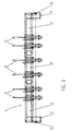
- Fig. 3 shows an apparatus 6 comprising three modules, namely a left end module 7, a right end module 9 and an intermediate module 8.
- Each module 7, 8, 9 is provided with two cramp stations 13. At the end modules 7 and 9 the cramp stations 13 closest to the ends of the apparatus 6 are mutually displaceable in the longitudinal direction of the apparatus so that the mutual distance of the cramp stations 13 in each end module 7, 9 can be varied whereby the distance from the outer cramp stations 13 to the ends of the apparatus can be varied.
- the length of the free ends of the reinforcing irons 4 at the sides of the rod mesh 3 can be varied.
- a gear box 11 with gear wheel 12 is arranged which is able to drive the rolling up of the rod mesh 3.
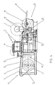
- Fig. 4 shows at the left side of the cramp station 13 a band roll 1 for a steel supporting band 2.
- the steel supporting band 2 can be drawn up to and along a cramp mounting block 14 forward to a rod mesh rolling up device 19.
- Above the cramp stations 13 is arranged a supporting beam 17 with a shelf 16 on which a bunch of rods of reinforcing iron 4 can be placed.
- a number of rods therefrom can be arranged in a magazine 15 immediately above the cramp mounting block 14.
- the connecting by cramps of reinforcing iron 4 to the steel supporting band 2 is carried out by a number of reinforcing irons 4 which are arranged transversely to the steel supporting band 2 being arranged on the supporting beam 17 of the cramp mounting block 14 and then cramped thereto. Thereafter the steel supporting band 2 is drawn forward a predetermined length of feed and connecting by cramps can continue or the net rolling up can be finished.
- the net rolling-up device 22 is shown to the right in Fig. 4 . It consists of a driving ring 18 being driven via a shaft from the gear wheel 12 and to which a front or outermost reinforcing iron 4 on the steel supporting band 2 of the rod mesh 3 has been attached, and around which the steel supporting band 2 with cramped reinforcing irons 4 is rolled up.
- the driving ring 18 may as shown follow upwards in accordance with the rolling up until a fully rolled up rod mesh 3 is achieved.
- a support 19 travelling with the outer circumference of the rod mesh, said support 19 may consist of two car rubber wheels 19.
- a chain wheel 23 with a friction hub being driven via a shaft from the gear box 11 may bring the car rubber wheel 19 closest to the band roll 1 in rotation clockwise or anticlockwise and may thus contribute to the rod mesh 2 being tightly wound up.
- a dispensing slide 21 along with the finished rod mesh 3 may roll when the following-on support 19 is lowered.
- the arrangement of the reinforcing iron 4 on steel supporting bands 2 can be made manually, partly automatic or fully-automatic.
- An embodiment for fully or partly automatic arrangement is shown in Fig. 5 .
- the upper sketch shows a magazine 15 and a supply device 30 for reinforcing iron to be arranged on the steel supporting band 4.
- the supply devices 30 are arranged between and outside the cramp stations 13 and are lifted when the rod mesh 3 is moved.
- the lower sketch shows a cramp station 13 where a cramp 5 from a cramp pistol 33 has been shot through the steel supporting band 2 against the inner wall form of a counter punch matrix 32 so that the two leg ends of the cramp 5 are brought into parallell extension tightly around the reinforcing iron 4 by the fastening.
- the counter punch matrix 32 is lifted while reinforcing irons 4 are arranged on the steel supporting band 2 and during the movement thereof.
- the apparatus is driven intermittently so that all parts are moved in mutual synchronism.
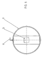
- Fig. 6 shows a driving ring 18 with a square hub hole 34 with one side a little larger than the cross section of a tubular driving shaft 28.
- a hook 35 is fastened to the circumference of the driving ring 18 to which a reinforcing iron 4 on the rod mesh 3 can be fastened, whereupon the rolling-up of the rod mesh 3 can be initiated with the point of the hook pointing in the rolling-up direction.
- Figs. 7 and 8 show the driving motor 24 of the gear box 11 and driving a friction hub 31.
- a chain or belt drive 29 therefrom drives a gear wheel 12 arranged on a hollow shaft 26 with a square driving hole 27 through which the tubular driving shaft 28 with the square cross section (cf. Fig. 9 ) for a driving ring 18 can be inserted.
- Fig. 9 shows a tubular driving shaft 28 with square cross section which is a little smaller than the cross section of the driving hole 27 in the gear wheel 12 and the cross section of the hub hole 34 in the driving ring 18.
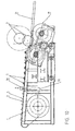
- Fig. 10 shows the cramp station 13 with lowered dispensing slide 21.
- the rod mesh 3 Before the rod mesh 3 is released from the net rolling device 22 and is guided to the dispensing slide 21 it should be fastened against unintended unrolling. This can be carried out by locking or winding it with wire or clips or providing it with hooklike locking means or the like.
- the driving rings 18 and cooperating auxiliary supporting rings arranged inside the rod mesh roll remain in the finished roll and may be returned to the manufacturer after the positioning of the rod mesh.
- the rod mesh 3 is guided to a rod mesh rolling device where the end forwarded from the steel supporting bands 2 synchronously are subject to a pulling force in the circumferential direction of at least two driving rings 18, said driving rings 18 are arranged practically coaxially as inner rod mesh rolling drive unit for the rod mesh 3 and having an outer diameter corresponding to the desired inner diameter for the rod mesh 3.
- Each of the driving rings 18 is supported by a support 19 following the circumference of the rod mesh 3 which supports the driving ring 18 during its rotation via the rod mesh 3 being rolled up.
- the following-on support 19 of the driving rings 18 may as mentioned take place by a couple of supporting wheels 19 arranged at mutual axial distance, such as car rubber wheels. Thus it is achieved that the full pulling force is exploited for tightening the rolling-up of the rod mesh.
- the outermost steel supporting bands 2 for the manufacture of the rod mesh 3 are each supported by a combined band guiding and cramping station 13 which is displaceably arranged in the transverse direction of the rod mesh 3 for adjustment of the predetermined protruding reinforcement iron end.
- a predetermined protruding length of the ends of the reinforcing irons at the sides of the rod mesh can be achieved.
- the rotation of the rod mesh 3 is locked preferably by each rotation stop during the manufacture of the rod mesh 3. Thus it is achieved that the tight rolling-up of the rod mesh is maintained.
- the rod mesh 3 which after the rolling-up is fastened to itself, e.g. by means of wire, is then as a finished unflexible roll guided downwards and is resting on the supporting wheels 19 by the lowering thereof, until the rod mesh roll 3 is delivered for the sliding or rolling down on at least two from the cramp station 13 downwardly inclining supporting rods 17 for delivery to a conveyor band, a trolley, in a transport container or a storage yard.
Landscapes
- Engineering & Computer Science (AREA)
- Architecture (AREA)
- Mechanical Engineering (AREA)
- Civil Engineering (AREA)
- Structural Engineering (AREA)
- Wire Processing (AREA)
- Reinforcement Elements For Buildings (AREA)
- Manufacturing Of Tubular Articles Or Embedded Moulded Articles (AREA)
- Sewage (AREA)
Claims (5)
- Verfahren zur Herstellung von Betonarmierungsrollennetz (3) umfassend in Längsrichtung verlaufende Stahlträgerbänder (2) und querverlaufende Armierungseisen (4), die an den Stahlträgerbändem (2) befestigt werden, dadurch gekennzeichnet, dass die Befestigung durch eine U-förmige Klammer (5) mit geradlinigem Körperteil mit seinen Beinenden durch das Stahlträgerband (2) und dicht um das Armierungseisen (4) herum erfolgt, so dass die Beinenden der Klammer (5) derart angebracht werden, dass sie einen Teil des Umkreises des Armierungseisens (4) von beiden Seiten umgeben und ihr Körperteil sich vorzugsweise in Längsrichtung des Stahlträgerbandes erstreckt.
- Verfahren nach Anspruch 1, dadurch gekennzeichnet, dass die Enden der Beinenden der Klammer (5) von der Innenwandform einer Auflagermatrix (32) derart geführt werden, dass die zwei Beinenden der Klammer (5) bei der Befestigung dazu gebracht werden, parallel nebeneinander dicht um das Armierungseisens (4) zu verlaufen, wobei die Klammer (5) vorzugsweise von einem Tacker (33) mit einem Klammermagazin (5) abgegeben wird, wobei der Tacker fest an einer Seite des Stahlträgerbandes (2) angeordnet ist und zur Befestigung des Armierungseisens (4) gegen das Stahlträgerband (2) und den Tacker (33) und zur Führung der Klammerbeinenden während der Befestigung mit der Auflagermatrix (32) auf der gegenüberliegenden Seite des Stahlträgerbandes (2) zusammenwirkt.
- Verfahren nach Anspruch 1, dadurch gekennzeichnet, dass die Beinenden der Klammer (5) von der Innenwandform einer Auflagermatrix (32) derart geführt werden, dass die zwei Beinenden der Klammer (5) bei der Befestigung dazu gebracht werden, parallel nebeneinander dicht um das Armierungseisen (4) zu verlaufen, wobei jede Klammer (5) von einem Tacker (33) mit einem Klammermagazin abgegeben wird, wobei der Tacker versetzbar entlang des Stahlträgerbandes (2) an einer Bandseite angeordnet ist und mit einer ebenfalls entlang des Bandes versetzbaren, auf der gegenüberliegende Bandseite angeordneten Auflagermatrix (32) zusammenwirkt, wobei die Matrix zur Befestigung des Armierungseisens (4) gegen das Band (2) und den Tacker (33) und zur Führung der Klammerbeinenden während der Befestigung angeordnet wird.
- Verfahren nach jedem der vorhergehenden Ansprüche, dadurch gekennzeichnet, dass die Armierungseisen (4) von einem Magazin durch eine Zuführungsvorrichtung (30) zur dem Tacker (33) gegenüberliegenden Seite des Stahlträgerbandes (2) zugeführt werden und gegen das Stahlträgerband (2) und jedes Eisen den Tacker durch einen Druck von der Auflagermatrix (32) bis Festsetzung einer Klammer durch den Tacker festgehalten werden.
- Gerät zur Anwendung bei der Herstellung von Betonarmierungsrollennetz (3) umfassend in Längsrichtung verlaufende Stahlträgerbänder (2) und querverlaufende Armierungseisen (4), die an den Stahlträgerbändern (2) befestigt sind, dadurch gekennzeichnet, dass es Befestigungsmittel zur Fixierung durch Klammern aufweist, und dass die Befestigung derart vorgesehen ist, dass sie durch Drücken einer U-förmigen Klammer (5), bei der der Körperteil der U geradlinig ist, durch das Stahlträgerband (2) mit ihren Beinen und dicht um das Armierungseisen (4) herum und mit dem Körperteil vorzugsweise in Längsrichtung des Stahlträgerbandes verlaufend erfolgt.
Applications Claiming Priority (3)
| Application Number | Priority Date | Filing Date | Title |
|---|---|---|---|
| DK200201129A DK176331B1 (da) | 2002-07-23 | 2002-07-23 | Fremgangsmåde og maskine til fremstilling af betonarmeringsrullenet |
| DK200201129 | 2002-07-23 | ||
| PCT/DK2003/000493 WO2004009266A1 (en) | 2002-07-23 | 2003-07-14 | Method and apparatus for the manufacture of concrete reinforcing rod mesh |
Publications (2)
| Publication Number | Publication Date |
|---|---|
| EP1539397A1 EP1539397A1 (de) | 2005-06-15 |
| EP1539397B1 true EP1539397B1 (de) | 2008-10-22 |
Family
ID=30470194
Family Applications (1)
| Application Number | Title | Priority Date | Filing Date |
|---|---|---|---|
| EP03764911A Expired - Lifetime EP1539397B1 (de) | 2002-07-23 | 2003-07-14 | Verfahren und vorrichtung zur herstellung eines betonverstärkungsstabgitters |
Country Status (6)
| Country | Link |
|---|---|
| EP (1) | EP1539397B1 (de) |
| AT (1) | ATE411858T1 (de) |
| AU (1) | AU2003244077A1 (de) |
| DE (1) | DE60324289D1 (de) |
| DK (2) | DK176331B1 (de) |
| WO (1) | WO2004009266A1 (de) |
Families Citing this family (5)
| Publication number | Priority date | Publication date | Assignee | Title |
|---|---|---|---|---|
| IT1392866B1 (it) | 2009-02-20 | 2012-04-02 | Schnell Spa | Metodo e apparecchiatura per realizzare armature per cemento armato |
| WO2014117214A1 (en) * | 2013-02-01 | 2014-08-07 | Leonard Francis Beyers | Rebar mesh and method of production |
| CN109702120B (zh) * | 2018-11-28 | 2024-01-26 | 建科机械(天津)股份有限公司 | 一种焊网机 |
| CN110560614B (zh) * | 2019-09-25 | 2024-11-05 | 武汉易知鸟科技有限公司 | 一种烟道矩形钢丝网笼折边成型设备 |
| DE102020126584B3 (de) * | 2020-10-09 | 2021-12-30 | Bam Ag | Maschine und Verfahren zur Herstellung einachsiger Bewehrungsstahlstabmatten |
Family Cites Families (5)
| Publication number | Priority date | Publication date | Assignee | Title |
|---|---|---|---|---|
| GB1500665A (en) * | 1976-07-07 | 1978-02-08 | Hulek A | Process of manufacturing wrought-iron lattices |
| EP0122883A3 (de) * | 1983-04-15 | 1987-06-03 | MRK Marketing and Management Techniques (UK) Limited | Verfahren zum maschinellen Verbinden der Stäbe eines Stabnetzes und Anlage zum maschinellen Verbinden der Stäbe eines Stabnetzes |
| DE9412405U1 (de) * | 1994-04-13 | 1995-08-10 | Häussler, Wilhelm, Dipl.-Ing. Dipl.-Kaufm., 87629 Füssen | Bewehrungsmatte für Stahlbeton-Flächentragwerke sowie Maschine zu deren Herstellung |
| JP3742938B2 (ja) * | 1997-08-14 | 2006-02-08 | 清水建設株式会社 | 鉄筋ユニットの組立装置 |
| DE10126441A1 (de) * | 2000-07-08 | 2002-01-17 | Ekkehard Friedl | Bewehrungseinheit |
-
2002
- 2002-07-23 DK DK200201129A patent/DK176331B1/da not_active IP Right Cessation
-
2003
- 2003-07-14 AU AU2003244077A patent/AU2003244077A1/en not_active Abandoned
- 2003-07-14 AT AT03764911T patent/ATE411858T1/de not_active IP Right Cessation
- 2003-07-14 WO PCT/DK2003/000493 patent/WO2004009266A1/en not_active Ceased
- 2003-07-14 EP EP03764911A patent/EP1539397B1/de not_active Expired - Lifetime
- 2003-07-14 DK DK03764911T patent/DK1539397T3/da active
- 2003-07-14 DE DE60324289T patent/DE60324289D1/de not_active Expired - Lifetime
Also Published As
| Publication number | Publication date |
|---|---|
| DK1539397T3 (da) | 2008-12-15 |
| DE60324289D1 (de) | 2008-12-04 |
| ATE411858T1 (de) | 2008-11-15 |
| WO2004009266A1 (en) | 2004-01-29 |
| DK200201129A (da) | 2004-01-24 |
| AU2003244077A1 (en) | 2004-02-09 |
| EP1539397A1 (de) | 2005-06-15 |
| DK176331B1 (da) | 2007-08-13 |
Similar Documents
| Publication | Publication Date | Title |
|---|---|---|
| JP5356664B2 (ja) | 鉄筋の自動結束方法及び装置 | |
| US20100294874A1 (en) | Winding device and method for fixing bundle or coil in the winding device | |
| US20030180098A1 (en) | Mobile system for manufacturing and installing reinforcing members | |
| EP1539397A1 (de) | VERFAHREN UND VORRICHTUNG ZUR HERSTELLUNG EINES BETONVERSTûRKUNGSSTABGITTERS | |
| CN113458297A (zh) | 一种建筑工地钢筋自动扎捆设备 | |
| JP6329260B2 (ja) | 巻癖形成装置 | |
| KR101444344B1 (ko) | 케이블 그리퍼 및 이를 갖춘 케이블 포설장치 | |
| KR101415719B1 (ko) | 텐셔너 일체형 스트랩핑 장치 | |
| US12589427B2 (en) | Method and apparatus for binding metal wires and similar products | |
| KR102587128B1 (ko) | 다중 와인더 구조의 호스 포장장치 | |
| CN211707757U (zh) | 一种易于收紧的带钢卷整平装置 | |
| KR19990037692A (ko) | 연장된 대상물을 같이 묶기 위한 결속기기 | |
| CN209651643U (zh) | 一种测量绳快速收放装置 | |
| KR101478768B1 (ko) | 다발의 파이프 집중장치 | |
| CN220487162U (zh) | 一种便捷式覆膜养护工具 | |
| EP1565294B1 (de) | Verfahren und vorrichtung zur herstellung eines länglichen produkts mit einer längs- und versteifungsbewehrung, sowie ein derart hergestelltes produkt | |
| EP3851617A1 (de) | Bausatz mit montagehilfe für transportanker | |
| CN221615759U (zh) | 播种机起播或调头的地膜滴灌带固定装置 | |
| EP1050502A2 (de) | Maschine zum Wiederaufwickeln von Drahtbunden mit dicht aneinanderliegenden Windungen | |
| CN211135344U (zh) | 一种轨枕系统用钢筋压直运输装置 | |
| GB2458326A (en) | Device for coiling a strap | |
| US3789651A (en) | Soft tube stretcher | |
| CN213083246U (zh) | 一种土木工程施工用防脱手的管材搬运装置 | |
| CN215977305U (zh) | 一种可快速安装的金属网片 | |
| CN211997283U (zh) | 建筑作业面垃圾捡拾装置 |
Legal Events
| Date | Code | Title | Description |
|---|---|---|---|
| PUAI | Public reference made under article 153(3) epc to a published international application that has entered the european phase |
Free format text: ORIGINAL CODE: 0009012 |
|
| 17P | Request for examination filed |
Effective date: 20050209 |
|
| AK | Designated contracting states |
Kind code of ref document: A1 Designated state(s): AT BE BG CH CY CZ DE DK EE ES FI FR GB GR HU IE IT LI LU MC NL PT RO SE SI SK TR |
|
| AX | Request for extension of the european patent |
Extension state: AL LT LV MK |
|
| DAX | Request for extension of the european patent (deleted) | ||
| GRAP | Despatch of communication of intention to grant a patent |
Free format text: ORIGINAL CODE: EPIDOSNIGR1 |
|
| RIC1 | Information provided on ipc code assigned before grant |
Ipc: B21F 27/08 20060101AFI20080430BHEP Ipc: E04C 5/04 20060101ALI20080430BHEP |
|
| GRAS | Grant fee paid |
Free format text: ORIGINAL CODE: EPIDOSNIGR3 |
|
| GRAA | (expected) grant |
Free format text: ORIGINAL CODE: 0009210 |
|
| AK | Designated contracting states |
Kind code of ref document: B1 Designated state(s): AT BE BG CH CY CZ DE DK EE ES FI FR GB GR HU IE IT LI LU MC NL PT RO SE SI SK TR |
|
| REG | Reference to a national code |
Ref country code: GB Ref legal event code: FG4D |
|
| REG | Reference to a national code |
Ref country code: CH Ref legal event code: EP |
|
| REG | Reference to a national code |
Ref country code: IE Ref legal event code: FG4D |
|
| REF | Corresponds to: |
Ref document number: 60324289 Country of ref document: DE Date of ref document: 20081204 Kind code of ref document: P |
|
| REG | Reference to a national code |
Ref country code: DK Ref legal event code: T3 |
|
| NLV1 | Nl: lapsed or annulled due to failure to fulfill the requirements of art. 29p and 29m of the patents act | ||
| PG25 | Lapsed in a contracting state [announced via postgrant information from national office to epo] |
Ref country code: AT Free format text: LAPSE BECAUSE OF FAILURE TO SUBMIT A TRANSLATION OF THE DESCRIPTION OR TO PAY THE FEE WITHIN THE PRESCRIBED TIME-LIMIT Effective date: 20081022 Ref country code: BG Free format text: LAPSE BECAUSE OF FAILURE TO SUBMIT A TRANSLATION OF THE DESCRIPTION OR TO PAY THE FEE WITHIN THE PRESCRIBED TIME-LIMIT Effective date: 20090122 Ref country code: ES Free format text: LAPSE BECAUSE OF FAILURE TO SUBMIT A TRANSLATION OF THE DESCRIPTION OR TO PAY THE FEE WITHIN THE PRESCRIBED TIME-LIMIT Effective date: 20090202 |
|
| PG25 | Lapsed in a contracting state [announced via postgrant information from national office to epo] |
Ref country code: FI Free format text: LAPSE BECAUSE OF FAILURE TO SUBMIT A TRANSLATION OF THE DESCRIPTION OR TO PAY THE FEE WITHIN THE PRESCRIBED TIME-LIMIT Effective date: 20081022 Ref country code: SI Free format text: LAPSE BECAUSE OF FAILURE TO SUBMIT A TRANSLATION OF THE DESCRIPTION OR TO PAY THE FEE WITHIN THE PRESCRIBED TIME-LIMIT Effective date: 20081022 Ref country code: PT Free format text: LAPSE BECAUSE OF FAILURE TO SUBMIT A TRANSLATION OF THE DESCRIPTION OR TO PAY THE FEE WITHIN THE PRESCRIBED TIME-LIMIT Effective date: 20090323 Ref country code: NL Free format text: LAPSE BECAUSE OF FAILURE TO SUBMIT A TRANSLATION OF THE DESCRIPTION OR TO PAY THE FEE WITHIN THE PRESCRIBED TIME-LIMIT Effective date: 20081022 |
|
| PG25 | Lapsed in a contracting state [announced via postgrant information from national office to epo] |
Ref country code: EE Free format text: LAPSE BECAUSE OF FAILURE TO SUBMIT A TRANSLATION OF THE DESCRIPTION OR TO PAY THE FEE WITHIN THE PRESCRIBED TIME-LIMIT Effective date: 20081022 Ref country code: RO Free format text: LAPSE BECAUSE OF FAILURE TO SUBMIT A TRANSLATION OF THE DESCRIPTION OR TO PAY THE FEE WITHIN THE PRESCRIBED TIME-LIMIT Effective date: 20081022 Ref country code: BE Free format text: LAPSE BECAUSE OF FAILURE TO SUBMIT A TRANSLATION OF THE DESCRIPTION OR TO PAY THE FEE WITHIN THE PRESCRIBED TIME-LIMIT Effective date: 20081022 |
|
| PLBE | No opposition filed within time limit |
Free format text: ORIGINAL CODE: 0009261 |
|
| STAA | Information on the status of an ep patent application or granted ep patent |
Free format text: STATUS: NO OPPOSITION FILED WITHIN TIME LIMIT |
|
| PG25 | Lapsed in a contracting state [announced via postgrant information from national office to epo] |
Ref country code: CZ Free format text: LAPSE BECAUSE OF FAILURE TO SUBMIT A TRANSLATION OF THE DESCRIPTION OR TO PAY THE FEE WITHIN THE PRESCRIBED TIME-LIMIT Effective date: 20081022 Ref country code: SE Free format text: LAPSE BECAUSE OF FAILURE TO SUBMIT A TRANSLATION OF THE DESCRIPTION OR TO PAY THE FEE WITHIN THE PRESCRIBED TIME-LIMIT Effective date: 20090122 Ref country code: IT Free format text: LAPSE BECAUSE OF FAILURE TO SUBMIT A TRANSLATION OF THE DESCRIPTION OR TO PAY THE FEE WITHIN THE PRESCRIBED TIME-LIMIT Effective date: 20081022 |
|
| 26N | No opposition filed |
Effective date: 20090723 |
|
| PG25 | Lapsed in a contracting state [announced via postgrant information from national office to epo] |
Ref country code: SK Free format text: LAPSE BECAUSE OF FAILURE TO SUBMIT A TRANSLATION OF THE DESCRIPTION OR TO PAY THE FEE WITHIN THE PRESCRIBED TIME-LIMIT Effective date: 20081022 |
|
| PG25 | Lapsed in a contracting state [announced via postgrant information from national office to epo] |
Ref country code: MC Free format text: LAPSE BECAUSE OF NON-PAYMENT OF DUE FEES Effective date: 20090731 |
|
| REG | Reference to a national code |
Ref country code: CH Ref legal event code: PL |
|
| GBPC | Gb: european patent ceased through non-payment of renewal fee |
Effective date: 20090714 |
|
| REG | Reference to a national code |
Ref country code: FR Ref legal event code: ST Effective date: 20100331 |
|
| REG | Reference to a national code |
Ref country code: IE Ref legal event code: MM4A |
|
| PG25 | Lapsed in a contracting state [announced via postgrant information from national office to epo] |
Ref country code: LI Free format text: LAPSE BECAUSE OF NON-PAYMENT OF DUE FEES Effective date: 20090731 Ref country code: CH Free format text: LAPSE BECAUSE OF NON-PAYMENT OF DUE FEES Effective date: 20090731 Ref country code: FR Free format text: LAPSE BECAUSE OF NON-PAYMENT OF DUE FEES Effective date: 20090731 |
|
| PG25 | Lapsed in a contracting state [announced via postgrant information from national office to epo] |
Ref country code: GB Free format text: LAPSE BECAUSE OF NON-PAYMENT OF DUE FEES Effective date: 20090714 |
|
| PG25 | Lapsed in a contracting state [announced via postgrant information from national office to epo] |
Ref country code: IE Free format text: LAPSE BECAUSE OF NON-PAYMENT OF DUE FEES Effective date: 20090714 |
|
| PG25 | Lapsed in a contracting state [announced via postgrant information from national office to epo] |
Ref country code: GR Free format text: LAPSE BECAUSE OF FAILURE TO SUBMIT A TRANSLATION OF THE DESCRIPTION OR TO PAY THE FEE WITHIN THE PRESCRIBED TIME-LIMIT Effective date: 20090123 |
|
| PG25 | Lapsed in a contracting state [announced via postgrant information from national office to epo] |
Ref country code: LU Free format text: LAPSE BECAUSE OF NON-PAYMENT OF DUE FEES Effective date: 20090714 |
|
| PG25 | Lapsed in a contracting state [announced via postgrant information from national office to epo] |
Ref country code: HU Free format text: LAPSE BECAUSE OF FAILURE TO SUBMIT A TRANSLATION OF THE DESCRIPTION OR TO PAY THE FEE WITHIN THE PRESCRIBED TIME-LIMIT Effective date: 20090423 |
|
| PG25 | Lapsed in a contracting state [announced via postgrant information from national office to epo] |
Ref country code: TR Free format text: LAPSE BECAUSE OF FAILURE TO SUBMIT A TRANSLATION OF THE DESCRIPTION OR TO PAY THE FEE WITHIN THE PRESCRIBED TIME-LIMIT Effective date: 20081022 |
|
| PG25 | Lapsed in a contracting state [announced via postgrant information from national office to epo] |
Ref country code: CY Free format text: LAPSE BECAUSE OF FAILURE TO SUBMIT A TRANSLATION OF THE DESCRIPTION OR TO PAY THE FEE WITHIN THE PRESCRIBED TIME-LIMIT Effective date: 20081022 |
|
| PGFP | Annual fee paid to national office [announced via postgrant information from national office to epo] |
Ref country code: DK Payment date: 20110727 Year of fee payment: 9 |
|
| PGFP | Annual fee paid to national office [announced via postgrant information from national office to epo] |
Ref country code: DE Payment date: 20120704 Year of fee payment: 10 |
|
| REG | Reference to a national code |
Ref country code: DK Ref legal event code: EBP |
|
| PG25 | Lapsed in a contracting state [announced via postgrant information from national office to epo] |
Ref country code: DK Free format text: LAPSE BECAUSE OF NON-PAYMENT OF DUE FEES Effective date: 20120731 |
|
| PG25 | Lapsed in a contracting state [announced via postgrant information from national office to epo] |
Ref country code: DE Free format text: LAPSE BECAUSE OF NON-PAYMENT OF DUE FEES Effective date: 20140201 |
|
| REG | Reference to a national code |
Ref country code: DE Ref legal event code: R119 Ref document number: 60324289 Country of ref document: DE Effective date: 20140201 |