EP1538644B1 - Dispositif de commande et/ou d'affichage pour l'habitacle d'un véhicule, nottament dispositif de commande pour un véhicule - Google Patents
Dispositif de commande et/ou d'affichage pour l'habitacle d'un véhicule, nottament dispositif de commande pour un véhicule Download PDFInfo
- Publication number
- EP1538644B1 EP1538644B1 EP04028803A EP04028803A EP1538644B1 EP 1538644 B1 EP1538644 B1 EP 1538644B1 EP 04028803 A EP04028803 A EP 04028803A EP 04028803 A EP04028803 A EP 04028803A EP 1538644 B1 EP1538644 B1 EP 1538644B1
- Authority
- EP
- European Patent Office
- Prior art keywords
- vehicle
- housing
- guide
- guide element
- encompassing
- Prior art date
- Legal status (The legal status is an assumption and is not a legal conclusion. Google has not performed a legal analysis and makes no representation as to the accuracy of the status listed.)
- Expired - Lifetime
Links
Images
Classifications
-
- B—PERFORMING OPERATIONS; TRANSPORTING
- B60—VEHICLES IN GENERAL
- B60R—VEHICLES, VEHICLE FITTINGS, OR VEHICLE PARTS, NOT OTHERWISE PROVIDED FOR
- B60R21/00—Arrangements or fittings on vehicles for protecting or preventing injuries to occupants or pedestrians in case of accidents or other traffic risks
- B60R21/02—Occupant safety arrangements or fittings, e.g. crash pads
- B60R21/09—Control elements or operating handles movable from an operative to an out-of-the way position, e.g. pedals, switch knobs, window cranks
-
- H—ELECTRICITY
- H01—ELECTRIC ELEMENTS
- H01H—ELECTRIC SWITCHES; RELAYS; SELECTORS; EMERGENCY PROTECTIVE DEVICES
- H01H3/00—Mechanisms for operating contacts
- H01H3/02—Operating parts, i.e. for operating driving mechanism by a mechanical force external to the switch
- H01H3/08—Turn knobs
-
- H—ELECTRICITY
- H01—ELECTRIC ELEMENTS
- H01H—ELECTRIC SWITCHES; RELAYS; SELECTORS; EMERGENCY PROTECTIVE DEVICES
- H01H3/00—Mechanisms for operating contacts
- H01H3/02—Operating parts, i.e. for operating driving mechanism by a mechanical force external to the switch
- H01H2003/026—Operating parts, i.e. for operating driving mechanism by a mechanical force external to the switch specially adapted to avoid injury to occupants of a car during an accident
-
- H—ELECTRICITY
- H01—ELECTRIC ELEMENTS
- H01H—ELECTRIC SWITCHES; RELAYS; SELECTORS; EMERGENCY PROTECTIVE DEVICES
- H01H3/00—Mechanisms for operating contacts
- H01H3/02—Operating parts, i.e. for operating driving mechanism by a mechanical force external to the switch
- H01H2003/0286—Operating parts, i.e. for operating driving mechanism by a mechanical force external to the switch having a weak point breaking or uncoupling on abnormal external force
-
- H—ELECTRICITY
- H01—ELECTRIC ELEMENTS
- H01H—ELECTRIC SWITCHES; RELAYS; SELECTORS; EMERGENCY PROTECTIVE DEVICES
- H01H3/00—Mechanisms for operating contacts
- H01H3/02—Operating parts, i.e. for operating driving mechanism by a mechanical force external to the switch
- H01H3/08—Turn knobs
- H01H2003/085—Retractable turn knobs, e.g. flush mounted
Definitions
- the present invention relates to an operating and / or display device for the interior of a vehicle, in particular to a vehicle operating unit.
- the ECE-R21 requires, among other things, that parts, such as switches or buttons, which protrude more than 9.5 mm from the surface of the control unit, must be such that they under the action of a forward horizontal horizontal force of 37, 8 daN, which is applied in the head impact test by means of a plunger with a flat pressure surface and a diameter of not more than 50 mm, are pressed into the surface of the control unit so that they do not protrude more than 9.5 mm or peel off.
- DE-A-25 57 859 describes an operating device according to the preamble of claim 1 for the instrument panel of a vehicle in the form of a knob which is slidably guided along guide pins and biased into a disengagement position by springs and against the biasing forces in the instrument panel is moved back into when an excessive force on the knob acts.
- DE 199 64 133 A1 describes a rotary switch with break points, which dips at an increased force in the axial direction in a front panel.
- the break points can be designed as yielding ribs with a predetermined breaking point or as spring elements.
- DE 100 54 588 A1 discloses an electronic device having a housing with a printed circuit board mounted therein.
- the printed circuit board carries operating elements which protrude out of the housing.
- the circuit board has predetermined breaking points, which lead to a separation of the control elements carrying part of the circuit board of the housing mounting position when acting on the controls in the direction of the circuit board inadmissible high forces.
- DE 298 22 594 U1 and DE 295 17 468 U1 relate to a projecting into the passenger compartment of a vehicle attachment such as handle, that is mounted on a shell part of the vehicle body. Associated with the storage is a yielding upon impact of an occupant under deformation component.
- an operating and / or display device for the interior of a vehicle in particular by a vehicle operating unit according to claim 1.
- the operating and / or display device may be individual actuators of a vehicle, such as a switch, a knob or a display, and in particular a (complete) control unit, such as. act the control unit of a vehicle heating or air conditioning.
- the operating device comprises a housing on which one or more encompassing elements are formed.
- the encompassing elements each serve to encompass corresponding guide elements which can be fastened to a vehicle or to a vehicle component, such as, for example, on the vehicle cockpit or on the rear side of the driver's seat.
- the housing is thus fastened with the help of the Umgreifimplantation and the guide elements on the vehicle.
- each encompassing element In normal operation, each encompassing element is held in a first position in a stationary manner on the guide element. In this first position, the actuating elements of the operating device from the surface of those vehicle component to which the operating device is attached, so for example from the vehicle cockpit, before and are therefore easy to handle by the vehicle occupants.
- the encompassing element After application of a predetermined maximum value exceeding, acting on the housing of the operating device and in the direction of extension of the guide element impact force, which can be generated for example by the impact of the head of a vehicle occupant, the encompassing element is along with the housing along the guide element from the first position moved to a second position, wherein the encompassing element is guided during this movement by the guide element. In this second position, the operating device is recessed into the surface of that vehicle component on which the operating device is arranged, so that the vehicle occupant can not incur any injuries due to the projection of the operating device.
- a significant advantage of the operating device according to the invention is that during the movement of the Umgreifimplantations from the first position in the second position no components of the operating device or the vehicle are destroyed.
- the housing of the operating device can be moved together with the Umgreifimplantationn in a simple manner along the guide elements from the second position back to the first position without a component must be replaced. This is particularly advantageous when the force, due to which the operating device is moved from the first position to the second position, inadvertently and not as a result of an accident is exercised.
- the encompassing element is arranged latching in the first position on the guide element in order to hold the encompassing element stationary during normal operation in this first position.
- the locking force between the encompassing element and the guide element is overcome, so that the encompassing element can move from its first position to its second position.
- the provision of a latching connection between the encompassing element and the guide element has the advantage that the latching force can be adjusted with small tolerances.
- the encompassing element according to the present invention is held in a latching manner in a groove formed in the guide element.
- the operating and / or display device further comprises a guiding element partially enclosing, latching held on this contact element on which abuts the encompassing element and holds the encompassing element stationary in its first position during normal operation.
- a guiding element partially enclosing, latching held on this contact element on which abuts the encompassing element and holds the encompassing element stationary in its first position during normal operation.
- the contact element is preferably ring-shaped or sleeve-shaped.
- the encompassing element is "floating" held on the guide member to produce a radial clearance.
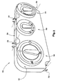
- Fig. 1 is a schematic view of a housing 10 of the operating device according to the present invention.
- the control device in the present case is the control device for actuating a vehicle heating system.
- a plurality of knobs 14, 16, 18 for adjusting the temperature, the blower power and the exit location of the air flow generated by the heating system are arranged.
- a plurality of encompassing elements 22 are formed, which serve for fastening the housing 10 to a vehicle.
- the encompassing elements 22 are integrally formed in the present case with the housing 10 and have an annular contour substantially.
- the ring contour is open on one side in order to increase the elasticity of the encompassing elements 22.
- the encompassing elements can assume different contours, for example a contour similar to that shown in FIG. 11, which will be explained in more detail below.
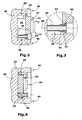
- FIG. 3 is a cross-sectional view of a first alternative of the operating device according to the present invention, which incorporates the in Fig. 1 shown housing 10 in the installed state shows.
- the housing 10 is in a recess 24 of a vehicle cockpit 26, which in Fig. 2 is shown only schematically, arranged by means of guide elements 28 which extend through the encompassing 22 therethrough.
- FIG. 3 a detail of the enlargement of Fig. 2 representing a section marked by a circle.
- the guide member 28 comprises a plurality of sections, namely, in Fig. 3 Viewed from left to right, a cylindrical guide portion 30, a subsequent to the guide portion 30 bead-shaped portion 32 having a larger outer diameter than the guide portion 30, a groove-like receiving portion 34 which has substantially the same outer diameter as the guide portion 30 and the Receiving the Umgreifimplantations 22 of the housing 10 is used, and finally a substantially annular projecting portion 36 which serves as a stop for the Umgreifelement 22 of the housing 10 in one direction.
- the guide element 28 has a through bore 38 in its longitudinal direction, that is from the guide section 30 to the annular projecting section 36.
- the guide member 28 is guided by means of a guided through the through hole 38 screw in the FIGS. 2 to 4 is indicated only by a dashed line, attached to the vehicle cockpit 26.
- the encompassing element 22 is held in the receiving portion 34 of the guide element 28 between the bead-shaped portion 32 and the annular projecting portion 36 of the guide member 28. This position is referred to below as the first position.
- the inner diameter of the substantially annular Umgreifimplantations 22 is slightly smaller than the diameter of the bead-shaped portion 32 of the guide member 28, so that the Umgreifelement 22 is securely held in the first position and can not accidentally slide over the bead-shaped portion 32.
- the front wall 12 of the housing 10 terminates substantially flush with the surface 40 of the vehicle cockpit 26, as shown in FIG Fig. 2 can be seen, so that arranged on the housing 10 rotary knob 14 and the in Fig. 2 concealed knobs 16 and 18 protrude relative to the surface 40 of the vehicle cockpit 26 and thus are well operated by the vehicle occupant.
- the encompassing elements 22 are pressed against the corresponding bead-shaped sections 32 of the guide elements 28.
- the inner diameter of the corresponding encompassing elements 22 widens in such a way that the encompassing elements 22 move in the direction of the maximum diameter of the corresponding bead-shaped sections 32 of the guide elements 28.
- the inner diameter of the individual encompassing elements 22 expands such that the respective encompassing elements 22 extend beyond the maximum diameter of the corresponding bead-shaped sections 32 of the guide elements 28 in the direction of the guide sections 30 of the guide elements 28 to move until the encompassing 22 and the rear wall 42 of the housing 10 abut against the rear wall 44 of the vehicle cockpit 26.
- This position is in Fig. 4 represented and is referred to below as the second position.
- the knobs 14, 16, 18 are completely recessed relative to the surface 40 of the vehicle cockpit 26. In this way, it is ensured that the impacting on the operating device according to the present invention body part of the vehicle occupant no serious injury by in the in Fig. 2 shown first position protruding knobs 14, 16, 18 learns.
- the predetermined maximum value F max of the impact force component F must not exceed 37.8 daN and is preferably chosen smaller than this value. It should be understood that the predetermined maximum value F max can be arbitrarily set.
- the predetermined one Maximum value F max is essentially dependent on the diameter difference between the maximum diameter of the bead-shaped portion 32 of the guide element 28 and the inner diameter of the encompassing element 22 of the housing 10.
- the predetermined maximum value F max can be influenced by the elasticity of the encompassing element 22.
- the elasticity of the encompassing element is dependent, on the one hand, on the material used for the encompassing element 22 and, on the other hand, on the shape of the encompassing element, that is to say on intentionally provided material weakening. The latter will be described below analogously with reference to FIG. 11 for a contact element.
- the radial clearance between the inner diameter of the encompassing element 22 of the housing 10 and the receiving portion 34 of the guide element 28 can be selected such that a "floating" receptacle of the Umgreifimplantations 22 is generated in the receiving portion 32.
- the manufacturing tolerance ranges of the housing 10 and the recess 24 of the vehicle cockpit 26 can be made larger, so that the housing 10 can be arranged more easily in the recess 24 of the vehicle cockpit 26 and the position tolerance ranges of the guide elements 28.
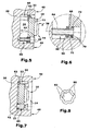
- FIGS. 5 to 8 show an alternative of the operating device according to the present invention.
- Fig. 5 is a cross-sectional view showing the in Fig. 1 shown housing 10 in a first position when installed shows. Similar to the previously described embodiments, the housing 10 is disposed in the recess 24 of the vehicle cockpit 26 and secured to the rear wall 44 of the vehicle cockpit 26 by means of screws 60 extending through the respective encompassing members 22 of the housing 10 are held in the first position as well as by means of abutment elements 62, which will be described in more detail with reference to FIG. In the first position, the front wall 12 of the housing 10 terminates substantially flush with the surface 40 of the vehicle cockpit 26 such that the knobs 14, 16, 18 protrude from the surface 40 of the vehicle cockpit 26 and thus are easily operated by the vehicle occupant.
- the guide member 60 a plurality of sections, namely, in Fig. 6 Viewed from left to right, a cylindrical guide portion 64, a bead-shaped portion 66 having a larger diameter than the guide portion 64, a subsequent to the bead-shaped portion 66 groove-shaped portion 68, whose Diameter substantially corresponding to the diameter of the guide portion 64 and which serves to receive the contact element 62, a receiving portion 68 whose diameter substantially corresponds to the diameter of the bead-shaped portion 66 and which serves to receive the Umgreifimplantations 22 of the housing 10, and finally a ring-shaped projecting Section 72, which serves as a stop for the Umgreifelement 22 in one direction.
- the abutment member 62 is substantially annular, as discussed below with reference to FIG Fig. 8 is explained in more detail.
- the inner diameter of the abutment element 62 is smaller than that of the bead-shaped portion 66 of the guide element 60, but larger than that of the guide portion 64.
- the inner diameter of the Umgreifides 22 is greater than the respective diameter of the sections 64, 66, 68 of the guide member 60, but less than the diameter of the annular protruding portion 72.
- each of the Umgreifetti 22 is arranged around the receiving portion 70 of the guide member 60 and held stationary between the abutment member 62 and the annular projecting portion 72 of the guide member 60.
- the encompassing elements 22 are respectively pressed against the abutment elements 62 and these in turn against the bead-shaped sections 66 of the corresponding guide elements 60, wherein the inner diameter of the abutment elements 62 widens gradually as a function of the height of the impact force component F acting on the abutment elements 62 , If the impact force component F reaches a predetermined maximum value, which is referred to below as F max , the inner diameter of the abutment element 62 widens so that the abutment element 62 projects beyond the maximum diameter of the bead-shaped section 66 of the guide element 60 and then further along the guide portion 64 in the direction of in Fig. 7 shown second position slides.
- F max a predetermined maximum value
- the housing 10 together with the protruding from the front wall 12 of the housing 10 knobs 14, 16, 18 completely sunk in the recess 24 of the vehicle cockpit 26. In this way, serious injuries to the vehicle occupant can be prevented.
- the predetermined maximum value F max of the impact force component F is arbitrarily adjustable. However, to comply with EU Directive ECE-R21, the value of F max should not exceed 37.8 daN.
- the predetermined maximum value F max is determined essentially by the difference in diameter of the inner diameter of the contact element 62 and the maximum diameter of the bead-shaped portion 66 of the guide element 60 and by the elasticity of the contact element 62.
- the elasticity of the abutment element 62 in turn can be influenced on the one hand by the material of which the abutment element 62 is made.
- the elasticity of the abutment element 62 or the expansion capability of the inner diameter of the abutment element 62 can be influenced by the shape of the abutment element 62, as in FIG Fig. 8 is shown by way of example.
- Fig. 8 shows a plan view of the abutment element 62.
- the abutment element 62 is substantially annular.
- the inner diameter is widened at regular intervals by corresponding recesses 80, so that the inner diameter defining sections 82 are weakened accordingly and thus can expand more easily.
- the outer diameter of the abutment element 62 essentially follows the contour generated by the recesses 80 and sections 82.
- the embodiments illustrated in the drawings may be modified or varied without departing from the scope of the claims.
- the encompassing 22 of the in the FIGS. 2 to 4 illustrated alternative of the operating device according to the present invention has a similar shape as that in Fig. 8 have shown investment element 62.
- the number of Umgreifimplantation and guide elements used is freely selectable.
- particular features described with reference to an alternative embodiment may be applied to the other alternative embodiments without departing from the scope of the invention as defined by the appended claims.
- not only the encompassing elements of the first alternative operating device according to the present invention "floating", ie with radial play, be held on the respective guide elements, but also those of the second alternative.
Landscapes
- Engineering & Computer Science (AREA)
- Mechanical Engineering (AREA)
- Fittings On The Vehicle Exterior For Carrying Loads, And Devices For Holding Or Mounting Articles (AREA)
- Mechanical Control Devices (AREA)
- Instrument Panels (AREA)
Claims (5)
- Dispositif de commande et/ou d'affichage pour l'habitacle d'un véhicule, notamment dispositif de commande pour un véhicule, comprenant- un boîtier (10),- au moins un élément de guidage (28; 50; 60) apte à être monté au véhicule, et- au moins un élément enveloppant (22) qui enveloppe l'élément de guidage (28; 50; 60) au moins partiellement et qui est situé au boîtier (10) et peut être guidé entre une première et une deuxième position le long de l'élément de guidage (28, 50; 60),- où, dans la première position, l'élément enveloppant (22) est retenu d'une manière stationnaire sur l'élément de guidage (28; 50; 60) et peut être guidé le long de l'élément de guidage (28; 50; 60) entre la première position et la deuxième position après l'application d'une force d'impact (F) dépassant un valeur maximum (Fmax) prédéterminé et agissant le long l'élément de guidage (28; 50; 60),caractérisé en ce que- l'élément enveloppant (22) est retenu de manière verrouillée dans la première position sur l'élément de guidage (28).
- Dispositif de commande et/ou d'affichage selon la revendication 1, caractérisé en ce que l'élément enveloppant (22) est retenu de manière verrouillée dans une rainure (34) formée dans l'élément de guidage (28).
- Dispositif de commande et/ou d'affichage selon la revendication 1, caractérisé en ce que le dispositif de commande et affichage en outre comprend un élément de contact (62) au moins partiellement enveloppant l'élément de guidage (60) et retenu sur le même de manière verrouillée.
- Dispositif de commande et/ou d'affichage selon la revendication 3, caractérisé en ce que l'élément de contact (62) est en forme annulaire ou d'un manche.
- Dispositif de commande et/ou d'affichage selon une quelconque des revendications précédentes, caractérisé en ce que l'élément enveloppant (22) est supporté de manière flottante sur l'élément de guidage (28; 50; 60).
Applications Claiming Priority (2)
| Application Number | Priority Date | Filing Date | Title |
|---|---|---|---|
| DE10357138 | 2003-12-06 | ||
| DE10357138A DE10357138B3 (de) | 2003-12-06 | 2003-12-06 | Bedien- und/oder Anzeigeeinrichtung für den Innenraum eines Fahrzeuges, insbesondere Fahrzeugbedieneinheit |
Publications (3)
| Publication Number | Publication Date |
|---|---|
| EP1538644A1 EP1538644A1 (fr) | 2005-06-08 |
| EP1538644B1 true EP1538644B1 (fr) | 2008-11-26 |
| EP1538644B8 EP1538644B8 (fr) | 2009-03-04 |
Family
ID=34442487
Family Applications (1)
| Application Number | Title | Priority Date | Filing Date |
|---|---|---|---|
| EP04028803A Expired - Lifetime EP1538644B8 (fr) | 2003-12-06 | 2004-12-04 | Dispositif de commande et/ou d'affichage pour l'habitacle d'un véhicule, nottament dispositif de commande pour un véhicule |
Country Status (4)
| Country | Link |
|---|---|
| EP (1) | EP1538644B8 (fr) |
| AT (1) | ATE415690T1 (fr) |
| DE (2) | DE10357138B3 (fr) |
| ES (1) | ES2318235T3 (fr) |
Families Citing this family (6)
| Publication number | Priority date | Publication date | Assignee | Title |
|---|---|---|---|---|
| DE102005053647B4 (de) * | 2005-11-10 | 2012-01-26 | Audi Ag | Befestigungsvorrichtung |
| DE102006050843A1 (de) * | 2006-10-27 | 2008-04-30 | Volkswagen Ag | Befestigungsanordnung für einen Tür-Zuziehgriff an einer Fahrzeugtür |
| DE102007042765A1 (de) * | 2007-09-07 | 2009-03-12 | Preh Gmbh | Bedienelement mit einem nach einem Kopfaufschlag reversiblen Bedienkopf für ein Fahrzeug |
| DE102008031685B4 (de) * | 2008-07-04 | 2022-06-15 | Preh Gmbh | Verbesserter Drehsteller |
| DE102008035128A1 (de) * | 2008-07-28 | 2010-02-04 | Marquardt Gmbh | Verfahren zum Befestigen eines Zündschlosses an einem Armaturenbrett und entsprechende Zündschlossbefestigungsanordnung |
| DE102011089765A1 (de) * | 2011-12-23 | 2013-06-27 | Behr-Hella Thermocontrol Gmbh | Bedien- und/oder Anzeigevorrichtung für den Innenraum eines Fahrzeuges |
Family Cites Families (6)
| Publication number | Priority date | Publication date | Assignee | Title |
|---|---|---|---|---|
| DE2557859C2 (de) * | 1975-01-31 | 1983-01-05 | Nissan Motor Co., Ltd., Yokohama, Kanagawa | Halterung von Schaltern für Instrumente an der Armaturentafel eines Kraftfahrzeugs |
| DE29517468U1 (de) * | 1995-11-04 | 1996-01-04 | Utescheny-Endos GmbH, 75059 Zaisenhausen | Griffeinrichtung für den Innenraum eines Fahrzeugs |
| DE29819392U1 (de) * | 1998-10-30 | 1999-01-07 | Volkswagen Ag, 38440 Wolfsburg | Lagerung eines in den Insassenraum eines Kraftfahrzeugs ragenden Anbauteils, insbesondere eines Haltegriffs |
| DE19964133A1 (de) * | 1999-11-22 | 2001-06-13 | Preh Elektro Feinmechanik | Drehschalter |
| DE10054588A1 (de) * | 2000-11-03 | 2002-05-08 | Siemens Ag | Für ein Fraftfahrzeug bestimmtes elektronisches Gerät |
| US6696769B2 (en) * | 2001-04-04 | 2004-02-24 | Halla Climate Control Corporation | Mode switch assembly of automobile having impact/load absorbing apparatus |
-
2003
- 2003-12-06 DE DE10357138A patent/DE10357138B3/de not_active Expired - Fee Related
-
2004
- 2004-12-04 DE DE502004008520T patent/DE502004008520D1/de not_active Expired - Lifetime
- 2004-12-04 ES ES04028803T patent/ES2318235T3/es not_active Expired - Lifetime
- 2004-12-04 EP EP04028803A patent/EP1538644B8/fr not_active Expired - Lifetime
- 2004-12-04 AT AT04028803T patent/ATE415690T1/de not_active IP Right Cessation
Also Published As
| Publication number | Publication date |
|---|---|
| EP1538644A1 (fr) | 2005-06-08 |
| EP1538644B8 (fr) | 2009-03-04 |
| ES2318235T3 (es) | 2009-05-01 |
| DE10357138B3 (de) | 2005-06-23 |
| ATE415690T1 (de) | 2008-12-15 |
| DE502004008520D1 (de) | 2009-01-08 |
Similar Documents
| Publication | Publication Date | Title |
|---|---|---|
| DE602004002232T2 (de) | Elektronisches Gerät | |
| DE60220574T2 (de) | Schaltanordnung für ein Kraftfahrzeug mit stoßabsorbierender Vorrichtung | |
| DE102014225569B4 (de) | Steuerknopfeinrichtung | |
| DE4303367C1 (de) | Sicherheitsschalter | |
| DE102008005256A1 (de) | Lenksäule mit Kunststoffgleithülse | |
| EP1102289A2 (fr) | Interrupteur rotatif | |
| EP1129886A2 (fr) | Elément commutateur éléctrique pour automobile avec zone de symbole distincte | |
| EP1538644B1 (fr) | Dispositif de commande et/ou d'affichage pour l'habitacle d'un véhicule, nottament dispositif de commande pour un véhicule | |
| EP1310698A2 (fr) | Elément déformable, notamment pour véhicules automobiles | |
| DE102020128465B3 (de) | Aufnahmevorrichtung für die Aufnahme einer Anzeigevorrichtung in dem Innenraum eines Fahrzeugs | |
| DE69502021T2 (de) | Trennbare verbindungsvorrichtung für eine lenksäule | |
| EP2048925A2 (fr) | Dispositif de fixation | |
| DE102013019940B4 (de) | Gassackabdeckung | |
| DE2818246C2 (de) | Belastungsanzeige für Sicherheitsgurtanordnungen | |
| EP3938238B1 (fr) | Commutateur de réglage de siège | |
| DE102018133697B4 (de) | Elektromechanische Kraftfahrzeuglenkung | |
| EP1716026B1 (fr) | Dispositif essuie-glace | |
| DE102014200930B4 (de) | Betätigungshebel | |
| DE102017222580B4 (de) | Sperrklinke für Fahrzeug-Armlehnenanordnung und Armlehnenanordnung | |
| DE19925859B4 (de) | Montagehilfe für eine Kraftfahrzeugtürkonstruktion | |
| DE10325856B4 (de) | Beschleunigungserfassungsvorrichtung | |
| DE202006014230U1 (de) | Bedienelement, insbesondere Drehbedienelement für eine Bedieneinheit einer Fahrzeugkomponente | |
| DE10232771B3 (de) | Sicherheitsvorrichtung einer geschlitzten Gabelhülse | |
| DE19718749B4 (de) | Umlenkbeschlag für Sicherheitsgurte | |
| DE102024110257A1 (de) | Lenksäule für ein Kraftfahrzeug |
Legal Events
| Date | Code | Title | Description |
|---|---|---|---|
| PUAI | Public reference made under article 153(3) epc to a published international application that has entered the european phase |
Free format text: ORIGINAL CODE: 0009012 |
|
| AK | Designated contracting states |
Kind code of ref document: A1 Designated state(s): AT BE BG CH CY CZ DE DK EE ES FI FR GB GR HU IE IS IT LI LT LU MC NL PL PT RO SE SI SK TR |
|
| AX | Request for extension of the european patent |
Extension state: AL BA HR LV MK YU |
|
| 17P | Request for examination filed |
Effective date: 20051117 |
|
| AKX | Designation fees paid |
Designated state(s): AT BE BG CH CY CZ DE DK EE ES FI FR GB GR HU IE IS IT LI LT LU MC NL PL PT RO SE SI SK TR |
|
| 17Q | First examination report despatched |
Effective date: 20060928 |
|
| GRAP | Despatch of communication of intention to grant a patent |
Free format text: ORIGINAL CODE: EPIDOSNIGR1 |
|
| GRAS | Grant fee paid |
Free format text: ORIGINAL CODE: EPIDOSNIGR3 |
|
| GRAA | (expected) grant |
Free format text: ORIGINAL CODE: 0009210 |
|
| AK | Designated contracting states |
Kind code of ref document: B1 Designated state(s): AT BE BG CH CY CZ DE DK EE ES FI FR GB GR HU IE IS IT LI LT LU MC NL PL PT RO SE SI SK TR |
|
| REG | Reference to a national code |
Ref country code: GB Ref legal event code: FG4D Free format text: NOT ENGLISH |
|
| REG | Reference to a national code |
Ref country code: CH Ref legal event code: EP |
|
| REG | Reference to a national code |
Ref country code: IE Ref legal event code: FG4D Free format text: LANGUAGE OF EP DOCUMENT: GERMAN |
|
| RBV | Designated contracting states (corrected) |
Designated state(s): AT BE BG CH CY CZ DK EE ES FI FR GB GR HU IE IS IT LI LT LU MC NL PL PT RO SE SI SK TR |
|
| REF | Corresponds to: |
Ref document number: 502004008520 Country of ref document: DE Date of ref document: 20090108 Kind code of ref document: P |
|
| REG | Reference to a national code |
Ref country code: SE Ref legal event code: TRGR |
|
| PG25 | Lapsed in a contracting state [announced via postgrant information from national office to epo] |
Ref country code: LT Free format text: LAPSE BECAUSE OF FAILURE TO SUBMIT A TRANSLATION OF THE DESCRIPTION OR TO PAY THE FEE WITHIN THE PRESCRIBED TIME-LIMIT Effective date: 20081126 |
|
| REG | Reference to a national code |
Ref country code: ES Ref legal event code: FG2A Ref document number: 2318235 Country of ref document: ES Kind code of ref document: T3 |
|
| NLV1 | Nl: lapsed or annulled due to failure to fulfill the requirements of art. 29p and 29m of the patents act | ||
| PG25 | Lapsed in a contracting state [announced via postgrant information from national office to epo] |
Ref country code: NL Free format text: LAPSE BECAUSE OF FAILURE TO SUBMIT A TRANSLATION OF THE DESCRIPTION OR TO PAY THE FEE WITHIN THE PRESCRIBED TIME-LIMIT Effective date: 20081126 Ref country code: SI Free format text: LAPSE BECAUSE OF FAILURE TO SUBMIT A TRANSLATION OF THE DESCRIPTION OR TO PAY THE FEE WITHIN THE PRESCRIBED TIME-LIMIT Effective date: 20081126 Ref country code: PL Free format text: LAPSE BECAUSE OF FAILURE TO SUBMIT A TRANSLATION OF THE DESCRIPTION OR TO PAY THE FEE WITHIN THE PRESCRIBED TIME-LIMIT Effective date: 20081126 Ref country code: FI Free format text: LAPSE BECAUSE OF FAILURE TO SUBMIT A TRANSLATION OF THE DESCRIPTION OR TO PAY THE FEE WITHIN THE PRESCRIBED TIME-LIMIT Effective date: 20081126 Ref country code: IS Free format text: LAPSE BECAUSE OF FAILURE TO SUBMIT A TRANSLATION OF THE DESCRIPTION OR TO PAY THE FEE WITHIN THE PRESCRIBED TIME-LIMIT Effective date: 20090326 |
|
| BERE | Be: lapsed |
Owner name: BEHR-HELLA THERMOCONTROL G.M.B.H. Effective date: 20081231 Owner name: BEHR G.M.B.H. & CO. KG Effective date: 20081231 |
|
| REG | Reference to a national code |
Ref country code: IE Ref legal event code: FD4D |
|
| PG25 | Lapsed in a contracting state [announced via postgrant information from national office to epo] |
Ref country code: RO Free format text: LAPSE BECAUSE OF FAILURE TO SUBMIT A TRANSLATION OF THE DESCRIPTION OR TO PAY THE FEE WITHIN THE PRESCRIBED TIME-LIMIT Effective date: 20081126 Ref country code: DK Free format text: LAPSE BECAUSE OF FAILURE TO SUBMIT A TRANSLATION OF THE DESCRIPTION OR TO PAY THE FEE WITHIN THE PRESCRIBED TIME-LIMIT Effective date: 20081126 Ref country code: BG Free format text: LAPSE BECAUSE OF FAILURE TO SUBMIT A TRANSLATION OF THE DESCRIPTION OR TO PAY THE FEE WITHIN THE PRESCRIBED TIME-LIMIT Effective date: 20090226 Ref country code: MC Free format text: LAPSE BECAUSE OF NON-PAYMENT OF DUE FEES Effective date: 20081231 Ref country code: EE Free format text: LAPSE BECAUSE OF FAILURE TO SUBMIT A TRANSLATION OF THE DESCRIPTION OR TO PAY THE FEE WITHIN THE PRESCRIBED TIME-LIMIT Effective date: 20081126 Ref country code: IE Free format text: LAPSE BECAUSE OF FAILURE TO SUBMIT A TRANSLATION OF THE DESCRIPTION OR TO PAY THE FEE WITHIN THE PRESCRIBED TIME-LIMIT Effective date: 20081126 |
|
| REG | Reference to a national code |
Ref country code: CH Ref legal event code: PL |
|
| PG25 | Lapsed in a contracting state [announced via postgrant information from national office to epo] |
Ref country code: CZ Free format text: LAPSE BECAUSE OF FAILURE TO SUBMIT A TRANSLATION OF THE DESCRIPTION OR TO PAY THE FEE WITHIN THE PRESCRIBED TIME-LIMIT Effective date: 20081126 Ref country code: PT Free format text: LAPSE BECAUSE OF FAILURE TO SUBMIT A TRANSLATION OF THE DESCRIPTION OR TO PAY THE FEE WITHIN THE PRESCRIBED TIME-LIMIT Effective date: 20090427 |
|
| PG25 | Lapsed in a contracting state [announced via postgrant information from national office to epo] |
Ref country code: SK Free format text: LAPSE BECAUSE OF FAILURE TO SUBMIT A TRANSLATION OF THE DESCRIPTION OR TO PAY THE FEE WITHIN THE PRESCRIBED TIME-LIMIT Effective date: 20081126 Ref country code: BE Free format text: LAPSE BECAUSE OF NON-PAYMENT OF DUE FEES Effective date: 20081231 |
|
| PLBE | No opposition filed within time limit |
Free format text: ORIGINAL CODE: 0009261 |
|
| STAA | Information on the status of an ep patent application or granted ep patent |
Free format text: STATUS: NO OPPOSITION FILED WITHIN TIME LIMIT |
|
| PG25 | Lapsed in a contracting state [announced via postgrant information from national office to epo] |
Ref country code: LI Free format text: LAPSE BECAUSE OF NON-PAYMENT OF DUE FEES Effective date: 20081231 Ref country code: CH Free format text: LAPSE BECAUSE OF NON-PAYMENT OF DUE FEES Effective date: 20081231 |
|
| 26N | No opposition filed |
Effective date: 20090827 |
|
| PG25 | Lapsed in a contracting state [announced via postgrant information from national office to epo] |
Ref country code: AT Free format text: LAPSE BECAUSE OF NON-PAYMENT OF DUE FEES Effective date: 20081204 |
|
| PG25 | Lapsed in a contracting state [announced via postgrant information from national office to epo] |
Ref country code: CY Free format text: LAPSE BECAUSE OF FAILURE TO SUBMIT A TRANSLATION OF THE DESCRIPTION OR TO PAY THE FEE WITHIN THE PRESCRIBED TIME-LIMIT Effective date: 20081126 Ref country code: HU Free format text: LAPSE BECAUSE OF FAILURE TO SUBMIT A TRANSLATION OF THE DESCRIPTION OR TO PAY THE FEE WITHIN THE PRESCRIBED TIME-LIMIT Effective date: 20090527 Ref country code: LU Free format text: LAPSE BECAUSE OF NON-PAYMENT OF DUE FEES Effective date: 20081204 |
|
| PG25 | Lapsed in a contracting state [announced via postgrant information from national office to epo] |
Ref country code: TR Free format text: LAPSE BECAUSE OF FAILURE TO SUBMIT A TRANSLATION OF THE DESCRIPTION OR TO PAY THE FEE WITHIN THE PRESCRIBED TIME-LIMIT Effective date: 20081126 |
|
| PG25 | Lapsed in a contracting state [announced via postgrant information from national office to epo] |
Ref country code: GR Free format text: LAPSE BECAUSE OF FAILURE TO SUBMIT A TRANSLATION OF THE DESCRIPTION OR TO PAY THE FEE WITHIN THE PRESCRIBED TIME-LIMIT Effective date: 20090227 |
|
| REG | Reference to a national code |
Ref country code: FR Ref legal event code: PLFP Year of fee payment: 12 |
|
| REG | Reference to a national code |
Ref country code: FR Ref legal event code: PLFP Year of fee payment: 13 |
|
| REG | Reference to a national code |
Ref country code: FR Ref legal event code: PLFP Year of fee payment: 14 |
|
| PGFP | Annual fee paid to national office [announced via postgrant information from national office to epo] |
Ref country code: SE Payment date: 20181219 Year of fee payment: 15 |
|
| PGFP | Annual fee paid to national office [announced via postgrant information from national office to epo] |
Ref country code: FR Payment date: 20181221 Year of fee payment: 15 Ref country code: GB Payment date: 20181220 Year of fee payment: 15 |
|
| PGFP | Annual fee paid to national office [announced via postgrant information from national office to epo] |
Ref country code: ES Payment date: 20190115 Year of fee payment: 15 Ref country code: IT Payment date: 20181231 Year of fee payment: 15 |
|
| REG | Reference to a national code |
Ref country code: SE Ref legal event code: EUG |
|
| GBPC | Gb: european patent ceased through non-payment of renewal fee |
Effective date: 20191204 |
|
| PG25 | Lapsed in a contracting state [announced via postgrant information from national office to epo] |
Ref country code: FR Free format text: LAPSE BECAUSE OF NON-PAYMENT OF DUE FEES Effective date: 20191231 Ref country code: SE Free format text: LAPSE BECAUSE OF NON-PAYMENT OF DUE FEES Effective date: 20191205 Ref country code: IT Free format text: LAPSE BECAUSE OF NON-PAYMENT OF DUE FEES Effective date: 20191204 Ref country code: GB Free format text: LAPSE BECAUSE OF NON-PAYMENT OF DUE FEES Effective date: 20191204 |
|
| REG | Reference to a national code |
Ref country code: ES Ref legal event code: FD2A Effective date: 20210531 |
|
| PG25 | Lapsed in a contracting state [announced via postgrant information from national office to epo] |
Ref country code: ES Free format text: LAPSE BECAUSE OF NON-PAYMENT OF DUE FEES Effective date: 20191205 |