EP1538644A1 - Bedien- und/oder Anzeigeeinrichtung für den Innenraum eines Fahrzeuges, insbesondere Fahrzeugbedieneinheit - Google Patents
Bedien- und/oder Anzeigeeinrichtung für den Innenraum eines Fahrzeuges, insbesondere Fahrzeugbedieneinheit Download PDFInfo
- Publication number
- EP1538644A1 EP1538644A1 EP04028803A EP04028803A EP1538644A1 EP 1538644 A1 EP1538644 A1 EP 1538644A1 EP 04028803 A EP04028803 A EP 04028803A EP 04028803 A EP04028803 A EP 04028803A EP 1538644 A1 EP1538644 A1 EP 1538644A1
- Authority
- EP
- European Patent Office
- Prior art keywords
- vehicle
- guide element
- housing
- guide
- encompassing
- Prior art date
- Legal status (The legal status is an assumption and is not a legal conclusion. Google has not performed a legal analysis and makes no representation as to the accuracy of the status listed.)
- Granted
Links
Images


Classifications
-
- B—PERFORMING OPERATIONS; TRANSPORTING
- B60—VEHICLES IN GENERAL
- B60R—VEHICLES, VEHICLE FITTINGS, OR VEHICLE PARTS, NOT OTHERWISE PROVIDED FOR
- B60R21/00—Arrangements or fittings on vehicles for protecting or preventing injuries to occupants or pedestrians in case of accidents or other traffic risks
- B60R21/02—Occupant safety arrangements or fittings, e.g. crash pads
- B60R21/09—Control elements or operating handles movable from an operative to an out-of-the way position, e.g. pedals, switch knobs, window cranks
-
- H—ELECTRICITY
- H01—ELECTRIC ELEMENTS
- H01H—ELECTRIC SWITCHES; RELAYS; SELECTORS; EMERGENCY PROTECTIVE DEVICES
- H01H3/00—Mechanisms for operating contacts
- H01H3/02—Operating parts, i.e. for operating driving mechanism by a mechanical force external to the switch
- H01H3/08—Turn knobs
-
- H—ELECTRICITY
- H01—ELECTRIC ELEMENTS
- H01H—ELECTRIC SWITCHES; RELAYS; SELECTORS; EMERGENCY PROTECTIVE DEVICES
- H01H3/00—Mechanisms for operating contacts
- H01H3/02—Operating parts, i.e. for operating driving mechanism by a mechanical force external to the switch
- H01H2003/026—Operating parts, i.e. for operating driving mechanism by a mechanical force external to the switch specially adapted to avoid injury to occupants of a car during an accident
-
- H—ELECTRICITY
- H01—ELECTRIC ELEMENTS
- H01H—ELECTRIC SWITCHES; RELAYS; SELECTORS; EMERGENCY PROTECTIVE DEVICES
- H01H3/00—Mechanisms for operating contacts
- H01H3/02—Operating parts, i.e. for operating driving mechanism by a mechanical force external to the switch
- H01H2003/0286—Operating parts, i.e. for operating driving mechanism by a mechanical force external to the switch having a weak point breaking or uncoupling on abnormal external force
-
- H—ELECTRICITY
- H01—ELECTRIC ELEMENTS
- H01H—ELECTRIC SWITCHES; RELAYS; SELECTORS; EMERGENCY PROTECTIVE DEVICES
- H01H3/00—Mechanisms for operating contacts
- H01H3/02—Operating parts, i.e. for operating driving mechanism by a mechanical force external to the switch
- H01H3/08—Turn knobs
- H01H2003/085—Retractable turn knobs, e.g. flush mounted
Definitions
- the present invention relates to an operating and / or display device for the interior of a vehicle, in particular a vehicle operating unit.
- the legislator has introduced specific design and operating regulations in terms of head impact on vehicle interior components such as the European directive ECE-R21.
- the ECE-R21 requires, among other things, that parts, such as switches or Buttons that protrude more than 9.5 mm from the surface of the control unit, be such that they are under the effect of a front-directed horizontal longitudinal force of 37.8 daN, the head impact test by means of a stamp with a flat printing surface and a diameter is applied by not more than 50 mm, in the surface of the control unit be pressed so that they do not protrude more than 9.5 mm or peel off.
- DE 199 64 133 A1 describes a rotary switch with break points, the at a increased force pressure in the axial direction in a front panel immersed.
- the break points can be as yielding ribs with a predetermined breaking point or be designed as spring elements.
- DE 100 54 588 A1 discloses an electronic device comprising a housing with a having in this fixed circuit board.
- the circuit board carries u.a. controls, which protrude from the housing.
- the circuit board has Predetermined breaking points that lead to a separation of the operating elements Part of the PCB lead from its housing mounting position when on the controls in the direction of the PCB act unacceptably high forces.
- DE 298 22 594 U1 and DE 295 17 468 U1 relate to a passenger compartment a vehicle protruding attachment such. Grab handle that on a shell component the vehicle body is mounted. The storage is assigned to a Upon impact of an occupant under deformation yielding component.
- an operating and / or display device for the interior of a vehicle, in particular a vehicle operating unit to be destroyed in the event of an accident without destruction can.
- a control device can be single actuators of a Vehicle, such as a switch, a knob or a Display, and in particular a (complete) operating unit, such.
- a Vehicle such as a switch, a knob or a Display
- a (complete) operating unit such.
- the operating device comprises a housing, on which a or a plurality of Umgreifimplantation are formed.
- the Umgreifimplantation serve each for encompassing corresponding guide elements attached to a vehicle or on a vehicle component, such as the vehicle cockpit or at the rear of the driver's seat.
- the Housing is therefore with the help of Umgreifimplantation and the guide elements attached to the vehicle.
- each encompassing element In normal operation, each encompassing element is stationary in a first position held the guide element. In this first position are the actuators the operating device from the surface of that vehicle component, where the operating device is attached, so for example from the vehicle cockpit, in front and are thus easy by the vehicle occupants to handle.
- the Umgreifelement After applying a predetermined maximum value Crossing, on the housing of the control device and in the direction of Extension of the guide element acting impact force, for example be generated by the impact of the head of a vehicle occupant can, the Umgreifelement is along with the housing along the guide element moved from the first position to a second position, wherein the encompassing element during this movement through the guide element is guided.
- the operating device In this second position, the operating device is in the surface that vehicle component on which the operating device is arranged is sunk, so that the vehicle occupant due to the supernatant the operating device can not incur any injuries.
- An essential advantage of the operating device according to the invention is that during the movement of the Umgreifimplantations from the first position in the second position no components of the operating device or the vehicle be destroyed.
- the Housing of the operating device together with the Umgreifimplantationn to simple Way along the guide elements from the second position back in the first position to be moved without a component must be replaced. This is particularly advantageous if the force due to which the operating device moved from the first position to the second position, accidentally and not as a result of an accident.
- the encompassing element latching in the first position is arranged on the guide element to the Umgreifelement during normal operation fixed in this first To hold a position.
- Overriding impact force is the locking force between the Umgreifelement and overcome the guide element, so that the Umgreifelement move from its first position to its second position.
- the Providing a latching connection between the encompassing element and the guide element has the advantage that the detent force with low tolerances is adjustable.
- the encompassing element according to the present invention is in held in the guide member groove detent.
- the encompassing element according to the present invention is resilient arranged in the first position on the guide element and is characterized by the fixed by the spring tension during normal operation stationary held in this first position.
- the spring When applying a predetermined Maximum value exceeding, acting on the operating device impact force the spring is compressed by the impact force, so that the encompassing element along the guide element from its first position can move to its second position, in which the operating device opposite the surface of the vehicle component to which it is attached, sunk is arranged.
- the operating and / or display device further includes the guide element partially enclosing, latching held on this investment element on which the Umgreifelement rests and that the Umgreifelement in normal operation keeps stationary in its first position.
- a predetermined Maximum impact force is the cogging force between the contact element and the groove overcome and the contact element together with the encompassing element along the guide element from the moved first position in the direction of the second position.
- this second Position is the operating device, as in the alternatives described above, arranged sunk, so that the risk of injury to the vehicle occupants is minimized.
- the contact element is preferably ring-shaped or sleeve-shaped.
- the encompassing element is "floating" held on the guide member to produce a radial clearance. In this way, when mounting the operating device to a vehicle, larger production tolerance ranges of the operating device or that vehicle component on which the operating device is to be arranged can be permitted.
- Fig. 1 is a schematic view of a housing 10 of the operating device according to the present invention.
- the operating device is in the present case to the control unit for operating a vehicle heating system.
- On a front wall 12 of the housing 10 are a plurality of knobs 14, 16, 18 for adjusting the temperature, the blower power and the Exit location of the air flow generated by the heating system arranged.
- On a side wall 20 of the housing 10 are a plurality of Umgreifimplantation 22 formed, which serve to fasten the housing 10 to a vehicle.
- the encompassing elements 22 are in the present case in one piece with the housing 10 formed and have substantially a ring contour.
- the Ring contour is open on one side to the elasticity of the Umgreifimplantation 22nd to increase.
- the encompassing elements are different Contours can take, for example, a similar contour as in Fig. 11 illustrated investment element, which will be explained in more detail below becomes.
- FIG. 2 is a cross-sectional view of a first alternative of the operating device according to the present invention, that shown in Fig. 1 Housing 10 in the installed state shows.
- the housing 10 is in a Recess 24 of a vehicle cockpit 26, shown in Fig. 2 only schematically is arranged by means of guide elements 28 extending through the Envelope 22 extend therethrough.
- FIG Fig. 3 is a detail enlargement of the in Fig. 2 representing a section marked by a circle.
- the guide element 28 comprises a plurality of sections, namely, viewed in Fig. 3 from left to right, a cylindrical Guide portion 30, a subsequent to the guide portion 30 bead-shaped section 32, which has a larger outer diameter than the guide section 30 has a groove-like receiving section 34, the substantially the same outer diameter as the guide portion 30 and for receiving the encompassing element 22 of the housing 10, and finally a substantially annular projecting portion 36, which in one direction as a stop for the Umgreifelement 22 of Housing 10 is used.
- the guide element 28 has in its longitudinal direction, So from the guide portion 30 to the annular protruding portion 36th a through hole 38.
- the guide member 28 is by means of a through the through hole 38 guided screw, which in the Fign. 2 to 4 indicated only by a dashed line on the vehicle cockpit 26 attached.
- the encompassing element 22 is in the receiving portion 34 of Guide element 28 between the bead-shaped portion 32 and the annular protruding portion 36 of the guide member 28 is held. This position is referred to below as the first position.
- the inner diameter the substantially annular Umgreifimplantations 22 is slight smaller than the diameter of the bead-shaped portion 32 of the Guide element 28, so that the Umgreifelement 22 safely in the first Position is held and not accidentally over the bead-shaped section 32 can slide.
- the front wall 12 of the housing closes 10 substantially flush with the surface 40 of the vehicle cockpit 26, as can be seen in Fig. 2, so that the arranged on the housing 10 Rotary knob 14 and the concealed in Fig. 2 knobs 16 and 18th protrude relative to the surface 40 of the vehicle cockpit 26 and thus good to be operated by the vehicle occupant.
- the encompassing elements 22 are pressed against the corresponding bead-shaped sections 32 of the guide elements 28.
- the inner diameter of the corresponding encompassing elements 22 widens in such a way that the encompassing elements 22 move in the direction of the maximum diameter of the corresponding bead-shaped sections 32 of the guide elements 28.
- the inner diameter of the individual encompassing elements 22 expands such that the respective encompassing elements 22 extend beyond the maximum diameter of the corresponding bead-shaped sections 32 of the guide elements 28 in the direction of the guide sections 30 of the guide elements 28 to move until the encompassing 22 and the rear wall 42 of the housing 10 abut against the rear wall 44 of the vehicle cockpit 26.
- This position is shown in Fig. 4 and is referred to below as the second position.
- the knobs 14, 16, 18 are completely recessed relative to the surface 40 of the vehicle cockpit 26. In this way, it is ensured that the body part of the vehicle occupant impacting on the operating device according to the present invention does not experience any serious injuries due to the rotary knobs 14, 16, 18 protruding in the first position shown in FIG.
- the predetermined maximum value F max of the impact force component F must not exceed 37.8 daN and is preferably chosen smaller than this value. It should be understood that the predetermined maximum value F max can be arbitrarily set.
- the predetermined maximum value F max is substantially dependent on the diameter difference between the maximum diameter of the bead-shaped portion 32 of the guide element 28 and the inner diameter of the encompassing element 22 of the housing 10.
- the predetermined maximum value F max can be influenced by the elasticity of the encompassing element 22.
- the elasticity of the encompassing element is dependent, on the one hand, on the material used for the encompassing element 22 and, on the other hand, on the shape of the encompassing element, that is to say on intentionally provided material weakening. The latter will be described below analogously with reference to FIG. 11 for a contact element.
- the radial clearance between the inner diameter the Umgreifimplantations 22 of the housing 10 and the receiving portion 34 of the guide member 28 can be selected such that a "floating" recording of Umgreifimplantations 22 in the receiving portion 32 is generated.
- the manufacturing tolerance ranges of the housing 10 and the recess 24 of the vehicle cockpit 26 larger be selected so that the housing 10 is simpler in the recess 24th the vehicle cockpit 26 and the positional tolerance ranges of the guide elements 28 can be arranged.
- FIGS. 5 to 7 show a second alternative of the operating device according to FIG of the present invention.
- FIG. 5 is a cross-sectional view similar to FIG. 1.
- the housing 10 is in the recess 24 of the vehicle cockpit 26 and arranged by means of guide elements 50, which extend through the encompassing elements 22 of the housing 10 and attached to the rear wall 44 of the vehicle cockpit 26, as well as held by springs 52 in the first position, which is below Referring to Fig. 6 is described in more detail.
- In this first position closes the front wall 12 of the housing 10 is substantially flush with the Surface 40 of the vehicle cockpit 26 from, so that the knobs 14, 16, 18 protrude from the surface 40 of the vehicle cockpit 26 and in this way easy to handle by the vehicle occupants.
- FIG. 6 is a partial enlargement of the one indicated by a circle in FIG. 5 Section.
- the guide element comprises 50 two sections, namely viewed in Fig. 6 from left to right, a cylindrical guide portion 54 and a subsequent thereto annular projecting portion 56, which in one direction as a stop for the encompassing element 22 of the housing 10 is used.
- the outer diameter the cylindrical guide section 54 of the guide element 50 is smaller than the inner diameter of the encompassing element 22, so that the Umgreifelement 22 along the cylindrical guide portion 54 of the guide element 50 is feasible, and the diameter of the annular protruding Section 56 of the guide element 50 is larger than the inner diameter of Umgreifiatas 22.
- the Umgreifelement 22 arranged on the guide element 50 such that the encompassing element 22 on the annular projecting portion 56 of the guide element 50 is present.
- an annular spring 52 is arranged, which is the Umgreifelement 22 against the annular projecting portion 56 of the guide element 50 presses. In this way, the housing 10 is stationary in the held first position.
- an impact force component is generated on the housing 10 and in the direction of the guide elements 50, which in FIG the arrow F is indicated.
- the encompassing elements 22 are pressed against the corresponding springs 52.
- F max the force applied by the springs 52 biasing force is overcome, so that the encompassing 22 moves against the bias along the guide portion 54 of the guide member 50 toward the second position, the in Fig. 7 is shown.
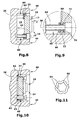
- FIG. 8 is a cross-sectional view illustrating FIG the housing 10 shown in Fig. 1 in a first position in the installed State shows. Similar to the embodiments described above the housing 10 is disposed in the recess 24 of the vehicle cockpit 26 and with the help of guide elements 60, which are characterized by the corresponding Umgreifimplantation 22 of the housing 10 and extend to the rear wall 44 of the Vehicle cockpits 26 are fastened by means of screws, as well as with help held by abutment members 62 in the first position, which is with reference 9 is described in more detail. In the first position closes the Front wall 12 of the housing 10 is substantially flush with the surface 40 of the vehicle cockpit 26, so that the knobs 14, 16, 18 of the Surface 40 of the vehicle cockpit 26 protrude and therefore simply by to operate the vehicle occupants.
- the guide element 60 has several sections on, namely, viewed from left to right in Fig. 9, a cylindrical Guide portion 64, a bead-shaped portion 66, a larger Diameter than the guide portion 64, a to the bead-shaped Section 66 subsequent groove-shaped portion 68, whose Diameter substantially the diameter of the guide portion 64th corresponds and which serves to receive the abutment element 62, a receiving portion 68, whose diameter is substantially equal to the diameter the bead-shaped portion 66 corresponds to and for receiving the Umgreifimplantations 22 of the housing 10 is used, and finally an annular protruding portion 72, in a direction as a stop for the Umgreifelement 22 serves.
- the abutment element 62 is substantially annular, such as will be explained in more detail below with reference to FIG. 11.
- the inner diameter of the abutment element 62 is smaller than that of the bead-shaped Section 66 of the guide member 60, but larger than the one the guide section 64.
- the inner diameter of the Umgreifimplantations 22 is larger than the respective diameter of the sections 64, 66, 68 of the Guide element 60, but smaller than the diameter of the annular The above section 72.
- first Position is each of the Umgreifimplantation 22 to the receiving portion 70 of the Guide element 60 is arranged and fixed between the contact element 62 and the annular projecting portion 72 of the guide member 60th held.
- the encompassing elements 22 are respectively pressed against the abutment elements 62 and these in turn against the bead-shaped sections 66 of the corresponding guide elements 60, wherein the inner diameter of the abutment elements 62 widens gradually as a function of the height of the impact force component F acting on the abutment elements 62 , If the impact force component F reaches a predetermined maximum value, which is referred to below as F max , then the inner diameter of the abutment element 62 expands such that the abutment element 62 projects beyond the maximum diameter of the bead-shaped section 66 of the guide element 60 and then further along the guide section 64 Direction of the second position shown in Fig. 10 slides.
- F max a predetermined maximum value
- the housing 10 together with the projecting from the front wall 12 of the housing 10 knobs 14, 16, 18 completely in the recess 24 of the vehicle cockpit 26th sunk. This can cause serious injury to the vehicle occupant be prevented.
- the predetermined maximum value F max of the impact force component F is arbitrarily adjustable. However, to comply with EU Directive ECE-R21, the value of F max should not exceed 37.8 daN.
- the predetermined maximum value F max is determined essentially by the difference in diameter of the inner diameter of the contact element 62 and the maximum diameter of the bead-shaped portion 66 of the guide element 60 and by the elasticity of the contact element 62.
- the elasticity of the abutment element 62 in turn can be influenced on the one hand by the material of which the abutment element 62 is made. On the other hand, the elasticity of the abutment element 62 or the expansion capability of the inner diameter of the abutment element 62 can be influenced by the shape of the abutment element 62, as shown by way of example in FIG. 11.
- Fig. 11 shows a plan view of the abutment element 62.
- the abutment element 62 substantially annular.
- To the expansion capacity of the inner diameter of the abutment element 62 is the inner diameter at regular intervals through appropriate recesses 80 widened, so that the inner diameter defining sections 82 are weakened accordingly and thus easier expand can.
- the outer diameter of the abutment element 62 essentially follows the contour generated by the recesses 80 and sections 82.
Landscapes
- Engineering & Computer Science (AREA)
- Mechanical Engineering (AREA)
- Fittings On The Vehicle Exterior For Carrying Loads, And Devices For Holding Or Mounting Articles (AREA)
- Mechanical Control Devices (AREA)
- Instrument Panels (AREA)
Abstract
Description
- einem Gehäuse,
- mindestens einem Führungselement, das an dem Fahrzeug befestigbar ist, und
- mindestens einem das Führungselement zumindest teilweise umgreifenden Umgreifelement, das an dem Gehäuse angeordnet und zwischen einer ersten und einer zweiten Stellung entlang des Führungselementes führbar ist,
- wobei das Umgreifelement in der ersten Stellung ortsfest an dem Führungselement gehalten ist und nach Aufbringen einer einen vorbestimmten Maximalwert überschreitenden, auf das Gehäuse und in Richtung des Führungselementes wirkenden Aufschlagkraft zwischen der ersten Stellung und der zweiten Stellung entlang des Führungselementes führbar ist.
Schließlich ist es gemäß der vorliegenden Erfindung vorteilhaft, dass das Umgreifelement "schwimmend" an dem Führungselement gehalten ist, um ein radiales Spiel zu erzeugen. Auf diese Weise können bei der Befestigung der Bedieneinrichtung an einem Fahrzeug größere Fertigungstoleranzbereiche der Bedieneinrichtung oder derjenigen Fahrzeugkomponente, an der die Bedieneinrichtung angeordnet werden soll, zugelassen werden.
- Fig. 1
- eine perspektivische Ansicht, die ein Ausführungsbeispiel eines Gehäuses der Bedieneinrichtung gemäß der vorliegenden Erfindung zeigt;
- Fig. 2
- eine Querschnittansicht einer ersten Alternative der Bedieneinrichtung gemäß der vorliegenden Erfindung, die das in Fig. 1 dargestellte Gehäuse im eingebauten Zustand in einer ersten Stellung zeigt;
- Fig. 3
- eine Ausschnittvergrößerung des in Fig. 2 durch einen Kreis gekennzeichneten Ausschnitts;
- Fig. 4
- eine Querschnittansicht der in Fig. 2 gezeigten ersten Alternative der Bedieneinrichtung gemäß der vorliegenden Erfindung, die das in Fig. 1 dargestellte Gehäuse im eingebauten Zustand in einer zweiten Stellung zeigt;
- Fig. 5
- eine Querschnittansicht einer zweiten Alternative der Bedieneinrichtung gemäß der vorliegenden Erfindung, die das in Fig. 1 dargestellte Gehäuse im eingebauten Zustand in einer ersten Stellung zeigt;
- Fig. 6
- eine Ausschnittvergrößerung des in Fig. 5 durch einen Kreis gekennzeichneten Ausschnitts;
- Fig. 7
- eine Querschnittansicht der zweiten Alternative der Bedieneinrichtung gemäß der vorliegenden Erfindung, die das in Fig. 1 dargestellte Gehäuse im eingebauten Zustand in einer zweiten Stellung zeigt;
- Fig. 8
- eine Querschnittansicht einer dritten Alternative der Bedieneinrichtung gemäß der vorliegenden Erfindung, die das in Fig. 1 dargestellte Gehäuse im eingebauten Zustand in einer ersten Stellung zeigt;
- Fig. 9
- eine Ausschnittvergrößerung des in Fig. 8 durch einen Kreis gekennzeichneten Ausschnitts;
- Fig. 10
- eine Querschnittansicht der dritten Alternative der Bedieneinrichtung gemäß der vorliegenden Erfindung, die das in Fig. 1 dargestellte Gehäuse im eingebauten Zustand in einer zweiten Stellung zeigt; und
- Fig. 11
- eine Draufsicht eines Anlageelementes, das in der dritten Alternative der Bedieneinrichtung gemäß der vorliegenden Erfindung verwendet wird.
Claims (9)
- Bedien- und/oder Anzeigeeinrichtung für den Innenraum eines Fahrzeugs, insbesondere Fahrzeugbedieneinheit, miteinem Gehäuse (10),mindestens einem Führungselement (28;50;60), das an dem Fahrzeug befestigbar ist, undmindestens einem das Führungselement (28;50;60) zumindest teilweise umgreifenden Umgreifelement (22), das an dem Gehäuse (10) angeordnet und zwischen einer ersten und einer zweiten Stellung entlang des Führungselementes (28;50;60) führbar ist,wobei das Umgreifelement (22) in der ersten Stellung ortsfest an dem Führungselement (28;50;60) gehalten ist und nach Aufbringen einer einen vorbestimmten Maximalwert (Fmax) überschreitenden, auf das Gehäuse und in Richtung des Führungselementes wirkenden Aufschlagkraft (F) zwischen der ersten Stellung und der zweiten Stellung entlang des Führungselementes (28;50;60) führbar ist.
- Bedien- und/oder Anzeigeeinrichtung nach Anspruch 1, dadurch gekennzeichnet, dass das Umgreifelement (22) rastend in der ersten Stellung an dem Führungselement (28) gehalten ist.
- Bedien- und/oder Anzeigeeinrichtung nach Anspruch 2, dadurch gekennzeichnet, dass das Umgreifelement (22) in einer in dem Führungselement (28) ausgebildeten Nut (34) rastend gehalten ist.
- Bedien- und/oder Anzeigeeinrichtung nach Anspruch 1, dadurch gekennzeichnet, dass das Umgreifelement (22) federnd in der ersten Stellung an dem Führungselement (50) gehalten ist.
- Bedien- und/oder Anzeigeeinrichtung nach Anspruch 4, dadurch gekennzeichnet, dass das Umgreifelement (22) dann, wenn das mindestens eine Führungselement (50) an dem Fahrzeug befestigt ist, zwischen einem an dem Führungselement ausgebildeten Anschlag (56) und einem Federelement angeordnet ist, wobei das Federelement zwischen dem Fahrzeug und dem Umgreifelement (22) eine Vorspannung erzeugt, die das Umgreifelement (22) in der ersten Stellung gegen den Anschlag (56) drückt.
- Bedien- und/oder Anzeigeeinrichtung nach Anspruch 4 oder 5, dadurch gekennzeichnet, dass das Federelement eine Schraubendruckfeder (52) ist.
- Bedien- und/oder Anzeigeeinrichtung nach Anspruch 1, dadurch gekennzeichnet, dass die Bedien- und Anzeigeeinrichtung ferner ein das Führungselement (60) zumindest teilweise umschließendes, rastend an diesem gehaltenes Anlageelement (62) aufweist, an dem das Umgreifelement (22) anliegt.
- Bedien- und/oder Anzeigeeinrichtung nach Anspruch 7, dadurch gekennzeichnet, dass das Anlageelement (62) ring- oder hülsenförmig ausgebildet ist.
- Bedien- und/oder Anzeigeeinrichtung nach einem der vorhergehenden Ansprüche, dadurch gekennzeichnet, dass das Umgreifelement (22) schwimmend an dem Führungselement (28;50;60) gehalten ist.
Applications Claiming Priority (2)
| Application Number | Priority Date | Filing Date | Title |
|---|---|---|---|
| DE10357138 | 2003-12-06 | ||
| DE10357138A DE10357138B3 (de) | 2003-12-06 | 2003-12-06 | Bedien- und/oder Anzeigeeinrichtung für den Innenraum eines Fahrzeuges, insbesondere Fahrzeugbedieneinheit |
Publications (3)
| Publication Number | Publication Date |
|---|---|
| EP1538644A1 true EP1538644A1 (de) | 2005-06-08 |
| EP1538644B1 EP1538644B1 (de) | 2008-11-26 |
| EP1538644B8 EP1538644B8 (de) | 2009-03-04 |
Family
ID=34442487
Family Applications (1)
| Application Number | Title | Priority Date | Filing Date |
|---|---|---|---|
| EP04028803A Expired - Lifetime EP1538644B8 (de) | 2003-12-06 | 2004-12-04 | Bedien- und/oder Anzeigeeinrichtung für den Innenraum eines Fahrzeuges, insbesondere Fahrzeugbedieneinheit |
Country Status (4)
| Country | Link |
|---|---|
| EP (1) | EP1538644B8 (de) |
| AT (1) | ATE415690T1 (de) |
| DE (2) | DE10357138B3 (de) |
| ES (1) | ES2318235T3 (de) |
Cited By (2)
| Publication number | Priority date | Publication date | Assignee | Title |
|---|---|---|---|---|
| DE102008035128A1 (de) * | 2008-07-28 | 2010-02-04 | Marquardt Gmbh | Verfahren zum Befestigen eines Zündschlosses an einem Armaturenbrett und entsprechende Zündschlossbefestigungsanordnung |
| DE102011089765A1 (de) | 2011-12-23 | 2013-06-27 | Behr-Hella Thermocontrol Gmbh | Bedien- und/oder Anzeigevorrichtung für den Innenraum eines Fahrzeuges |
Families Citing this family (4)
| Publication number | Priority date | Publication date | Assignee | Title |
|---|---|---|---|---|
| DE102005053647B4 (de) * | 2005-11-10 | 2012-01-26 | Audi Ag | Befestigungsvorrichtung |
| DE102006050843A1 (de) * | 2006-10-27 | 2008-04-30 | Volkswagen Ag | Befestigungsanordnung für einen Tür-Zuziehgriff an einer Fahrzeugtür |
| DE102007042765A1 (de) * | 2007-09-07 | 2009-03-12 | Preh Gmbh | Bedienelement mit einem nach einem Kopfaufschlag reversiblen Bedienkopf für ein Fahrzeug |
| DE102008031685B4 (de) * | 2008-07-04 | 2022-06-15 | Preh Gmbh | Verbesserter Drehsteller |
Citations (2)
| Publication number | Priority date | Publication date | Assignee | Title |
|---|---|---|---|---|
| DE2557859A1 (de) * | 1975-01-31 | 1976-08-05 | Nissan Motor | Einrichtung zum anbringen von instrumenten, schaltern, einem radio o.dgl. auf dem armaturenbrett eines kraftfahrzeugs |
| EP1248274A2 (de) * | 2001-04-04 | 2002-10-09 | Halla Climate Control Corporation | Schaltanordnung für ein Kraftfahrzeug mit stossabsorbierende Vorrichtung |
Family Cites Families (4)
| Publication number | Priority date | Publication date | Assignee | Title |
|---|---|---|---|---|
| DE29517468U1 (de) * | 1995-11-04 | 1996-01-04 | Utescheny-Endos GmbH, 75059 Zaisenhausen | Griffeinrichtung für den Innenraum eines Fahrzeugs |
| DE29819392U1 (de) * | 1998-10-30 | 1999-01-07 | Volkswagen Ag, 38440 Wolfsburg | Lagerung eines in den Insassenraum eines Kraftfahrzeugs ragenden Anbauteils, insbesondere eines Haltegriffs |
| DE19964133A1 (de) * | 1999-11-22 | 2001-06-13 | Preh Elektro Feinmechanik | Drehschalter |
| DE10054588A1 (de) * | 2000-11-03 | 2002-05-08 | Siemens Ag | Für ein Fraftfahrzeug bestimmtes elektronisches Gerät |
-
2003
- 2003-12-06 DE DE10357138A patent/DE10357138B3/de not_active Expired - Fee Related
-
2004
- 2004-12-04 DE DE502004008520T patent/DE502004008520D1/de not_active Expired - Lifetime
- 2004-12-04 ES ES04028803T patent/ES2318235T3/es not_active Expired - Lifetime
- 2004-12-04 EP EP04028803A patent/EP1538644B8/de not_active Expired - Lifetime
- 2004-12-04 AT AT04028803T patent/ATE415690T1/de not_active IP Right Cessation
Patent Citations (2)
| Publication number | Priority date | Publication date | Assignee | Title |
|---|---|---|---|---|
| DE2557859A1 (de) * | 1975-01-31 | 1976-08-05 | Nissan Motor | Einrichtung zum anbringen von instrumenten, schaltern, einem radio o.dgl. auf dem armaturenbrett eines kraftfahrzeugs |
| EP1248274A2 (de) * | 2001-04-04 | 2002-10-09 | Halla Climate Control Corporation | Schaltanordnung für ein Kraftfahrzeug mit stossabsorbierende Vorrichtung |
Cited By (2)
| Publication number | Priority date | Publication date | Assignee | Title |
|---|---|---|---|---|
| DE102008035128A1 (de) * | 2008-07-28 | 2010-02-04 | Marquardt Gmbh | Verfahren zum Befestigen eines Zündschlosses an einem Armaturenbrett und entsprechende Zündschlossbefestigungsanordnung |
| DE102011089765A1 (de) | 2011-12-23 | 2013-06-27 | Behr-Hella Thermocontrol Gmbh | Bedien- und/oder Anzeigevorrichtung für den Innenraum eines Fahrzeuges |
Also Published As
| Publication number | Publication date |
|---|---|
| EP1538644B8 (de) | 2009-03-04 |
| ES2318235T3 (es) | 2009-05-01 |
| DE10357138B3 (de) | 2005-06-23 |
| ATE415690T1 (de) | 2008-12-15 |
| DE502004008520D1 (de) | 2009-01-08 |
| EP1538644B1 (de) | 2008-11-26 |
Similar Documents
| Publication | Publication Date | Title |
|---|---|---|
| DE60220574T2 (de) | Schaltanordnung für ein Kraftfahrzeug mit stoßabsorbierender Vorrichtung | |
| DE602004002232T2 (de) | Elektronisches Gerät | |
| EP1102289B1 (de) | Drehschalter | |
| DE4344615C2 (de) | Lenkrad | |
| EP0828207A2 (de) | Drehknopfoberteil | |
| EP1248914B1 (de) | Befestigungsvorrichtung für pedale in kraftfahrzeugen | |
| DE2914280A1 (de) | Elektrischer dreh- oder zugschalter, insbesondere fuer kraftfahrzeuge | |
| EP0609672A2 (de) | Sicherheitsschalter | |
| WO1999046138A1 (de) | Betätigungsvorrichtung für ein kraftfahrzeug | |
| EP1310698A2 (de) | Deformationselement, insbesondere für Kraftfahrzeuge | |
| DE10357138B3 (de) | Bedien- und/oder Anzeigeeinrichtung für den Innenraum eines Fahrzeuges, insbesondere Fahrzeugbedieneinheit | |
| DE102020128465B3 (de) | Aufnahmevorrichtung für die Aufnahme einer Anzeigevorrichtung in dem Innenraum eines Fahrzeugs | |
| DE102010026725B4 (de) | Pufferelement mit verbessertem Abbau von Aufprallenergie | |
| EP2048925A2 (de) | Befestigungsvorrichtung | |
| DE60302244T2 (de) | Pedalsicherheitssystem | |
| DE69924909T2 (de) | Lenkvorrichtung | |
| DE102013019940B4 (de) | Gassackabdeckung | |
| DE2818246C2 (de) | Belastungsanzeige für Sicherheitsgurtanordnungen | |
| DE102012011982B4 (de) | Gassackabdeckung mit einem Emblem und Verfahren zu ihrer Herstellung | |
| DE602005002609T2 (de) | Bedienungsfrontklappe | |
| EP3938238B1 (de) | Sitzverstellschalter | |
| EP0466021A2 (de) | Beschleunigungsschalter mit Schnappfeder | |
| EP1716026B1 (de) | Scheibenwischvorrichtung | |
| DE10261831A1 (de) | Aufprallweiches Betätigungselement zur Anordnung in einem Fahrzeug | |
| DE102021110731B3 (de) | Airbag-Anordnung |
Legal Events
| Date | Code | Title | Description |
|---|---|---|---|
| PUAI | Public reference made under article 153(3) epc to a published international application that has entered the european phase |
Free format text: ORIGINAL CODE: 0009012 |
|
| AK | Designated contracting states |
Kind code of ref document: A1 Designated state(s): AT BE BG CH CY CZ DE DK EE ES FI FR GB GR HU IE IS IT LI LT LU MC NL PL PT RO SE SI SK TR |
|
| AX | Request for extension of the european patent |
Extension state: AL BA HR LV MK YU |
|
| 17P | Request for examination filed |
Effective date: 20051117 |
|
| AKX | Designation fees paid |
Designated state(s): AT BE BG CH CY CZ DE DK EE ES FI FR GB GR HU IE IS IT LI LT LU MC NL PL PT RO SE SI SK TR |
|
| 17Q | First examination report despatched |
Effective date: 20060928 |
|
| GRAP | Despatch of communication of intention to grant a patent |
Free format text: ORIGINAL CODE: EPIDOSNIGR1 |
|
| GRAS | Grant fee paid |
Free format text: ORIGINAL CODE: EPIDOSNIGR3 |
|
| GRAA | (expected) grant |
Free format text: ORIGINAL CODE: 0009210 |
|
| AK | Designated contracting states |
Kind code of ref document: B1 Designated state(s): AT BE BG CH CY CZ DE DK EE ES FI FR GB GR HU IE IS IT LI LT LU MC NL PL PT RO SE SI SK TR |
|
| REG | Reference to a national code |
Ref country code: GB Ref legal event code: FG4D Free format text: NOT ENGLISH |
|
| REG | Reference to a national code |
Ref country code: CH Ref legal event code: EP |
|
| REG | Reference to a national code |
Ref country code: IE Ref legal event code: FG4D Free format text: LANGUAGE OF EP DOCUMENT: GERMAN |
|
| RBV | Designated contracting states (corrected) |
Designated state(s): AT BE BG CH CY CZ DK EE ES FI FR GB GR HU IE IS IT LI LT LU MC NL PL PT RO SE SI SK TR |
|
| REF | Corresponds to: |
Ref document number: 502004008520 Country of ref document: DE Date of ref document: 20090108 Kind code of ref document: P |
|
| REG | Reference to a national code |
Ref country code: SE Ref legal event code: TRGR |
|
| PG25 | Lapsed in a contracting state [announced via postgrant information from national office to epo] |
Ref country code: LT Free format text: LAPSE BECAUSE OF FAILURE TO SUBMIT A TRANSLATION OF THE DESCRIPTION OR TO PAY THE FEE WITHIN THE PRESCRIBED TIME-LIMIT Effective date: 20081126 |
|
| REG | Reference to a national code |
Ref country code: ES Ref legal event code: FG2A Ref document number: 2318235 Country of ref document: ES Kind code of ref document: T3 |
|
| NLV1 | Nl: lapsed or annulled due to failure to fulfill the requirements of art. 29p and 29m of the patents act | ||
| PG25 | Lapsed in a contracting state [announced via postgrant information from national office to epo] |
Ref country code: NL Free format text: LAPSE BECAUSE OF FAILURE TO SUBMIT A TRANSLATION OF THE DESCRIPTION OR TO PAY THE FEE WITHIN THE PRESCRIBED TIME-LIMIT Effective date: 20081126 Ref country code: SI Free format text: LAPSE BECAUSE OF FAILURE TO SUBMIT A TRANSLATION OF THE DESCRIPTION OR TO PAY THE FEE WITHIN THE PRESCRIBED TIME-LIMIT Effective date: 20081126 Ref country code: PL Free format text: LAPSE BECAUSE OF FAILURE TO SUBMIT A TRANSLATION OF THE DESCRIPTION OR TO PAY THE FEE WITHIN THE PRESCRIBED TIME-LIMIT Effective date: 20081126 Ref country code: FI Free format text: LAPSE BECAUSE OF FAILURE TO SUBMIT A TRANSLATION OF THE DESCRIPTION OR TO PAY THE FEE WITHIN THE PRESCRIBED TIME-LIMIT Effective date: 20081126 Ref country code: IS Free format text: LAPSE BECAUSE OF FAILURE TO SUBMIT A TRANSLATION OF THE DESCRIPTION OR TO PAY THE FEE WITHIN THE PRESCRIBED TIME-LIMIT Effective date: 20090326 |
|
| BERE | Be: lapsed |
Owner name: BEHR-HELLA THERMOCONTROL G.M.B.H. Effective date: 20081231 Owner name: BEHR G.M.B.H. & CO. KG Effective date: 20081231 |
|
| REG | Reference to a national code |
Ref country code: IE Ref legal event code: FD4D |
|
| PG25 | Lapsed in a contracting state [announced via postgrant information from national office to epo] |
Ref country code: RO Free format text: LAPSE BECAUSE OF FAILURE TO SUBMIT A TRANSLATION OF THE DESCRIPTION OR TO PAY THE FEE WITHIN THE PRESCRIBED TIME-LIMIT Effective date: 20081126 Ref country code: DK Free format text: LAPSE BECAUSE OF FAILURE TO SUBMIT A TRANSLATION OF THE DESCRIPTION OR TO PAY THE FEE WITHIN THE PRESCRIBED TIME-LIMIT Effective date: 20081126 Ref country code: BG Free format text: LAPSE BECAUSE OF FAILURE TO SUBMIT A TRANSLATION OF THE DESCRIPTION OR TO PAY THE FEE WITHIN THE PRESCRIBED TIME-LIMIT Effective date: 20090226 Ref country code: MC Free format text: LAPSE BECAUSE OF NON-PAYMENT OF DUE FEES Effective date: 20081231 Ref country code: EE Free format text: LAPSE BECAUSE OF FAILURE TO SUBMIT A TRANSLATION OF THE DESCRIPTION OR TO PAY THE FEE WITHIN THE PRESCRIBED TIME-LIMIT Effective date: 20081126 Ref country code: IE Free format text: LAPSE BECAUSE OF FAILURE TO SUBMIT A TRANSLATION OF THE DESCRIPTION OR TO PAY THE FEE WITHIN THE PRESCRIBED TIME-LIMIT Effective date: 20081126 |
|
| REG | Reference to a national code |
Ref country code: CH Ref legal event code: PL |
|
| PG25 | Lapsed in a contracting state [announced via postgrant information from national office to epo] |
Ref country code: CZ Free format text: LAPSE BECAUSE OF FAILURE TO SUBMIT A TRANSLATION OF THE DESCRIPTION OR TO PAY THE FEE WITHIN THE PRESCRIBED TIME-LIMIT Effective date: 20081126 Ref country code: PT Free format text: LAPSE BECAUSE OF FAILURE TO SUBMIT A TRANSLATION OF THE DESCRIPTION OR TO PAY THE FEE WITHIN THE PRESCRIBED TIME-LIMIT Effective date: 20090427 |
|
| PG25 | Lapsed in a contracting state [announced via postgrant information from national office to epo] |
Ref country code: SK Free format text: LAPSE BECAUSE OF FAILURE TO SUBMIT A TRANSLATION OF THE DESCRIPTION OR TO PAY THE FEE WITHIN THE PRESCRIBED TIME-LIMIT Effective date: 20081126 Ref country code: BE Free format text: LAPSE BECAUSE OF NON-PAYMENT OF DUE FEES Effective date: 20081231 |
|
| PLBE | No opposition filed within time limit |
Free format text: ORIGINAL CODE: 0009261 |
|
| STAA | Information on the status of an ep patent application or granted ep patent |
Free format text: STATUS: NO OPPOSITION FILED WITHIN TIME LIMIT |
|
| PG25 | Lapsed in a contracting state [announced via postgrant information from national office to epo] |
Ref country code: LI Free format text: LAPSE BECAUSE OF NON-PAYMENT OF DUE FEES Effective date: 20081231 Ref country code: CH Free format text: LAPSE BECAUSE OF NON-PAYMENT OF DUE FEES Effective date: 20081231 |
|
| 26N | No opposition filed |
Effective date: 20090827 |
|
| PG25 | Lapsed in a contracting state [announced via postgrant information from national office to epo] |
Ref country code: AT Free format text: LAPSE BECAUSE OF NON-PAYMENT OF DUE FEES Effective date: 20081204 |
|
| PG25 | Lapsed in a contracting state [announced via postgrant information from national office to epo] |
Ref country code: CY Free format text: LAPSE BECAUSE OF FAILURE TO SUBMIT A TRANSLATION OF THE DESCRIPTION OR TO PAY THE FEE WITHIN THE PRESCRIBED TIME-LIMIT Effective date: 20081126 Ref country code: HU Free format text: LAPSE BECAUSE OF FAILURE TO SUBMIT A TRANSLATION OF THE DESCRIPTION OR TO PAY THE FEE WITHIN THE PRESCRIBED TIME-LIMIT Effective date: 20090527 Ref country code: LU Free format text: LAPSE BECAUSE OF NON-PAYMENT OF DUE FEES Effective date: 20081204 |
|
| PG25 | Lapsed in a contracting state [announced via postgrant information from national office to epo] |
Ref country code: TR Free format text: LAPSE BECAUSE OF FAILURE TO SUBMIT A TRANSLATION OF THE DESCRIPTION OR TO PAY THE FEE WITHIN THE PRESCRIBED TIME-LIMIT Effective date: 20081126 |
|
| PG25 | Lapsed in a contracting state [announced via postgrant information from national office to epo] |
Ref country code: GR Free format text: LAPSE BECAUSE OF FAILURE TO SUBMIT A TRANSLATION OF THE DESCRIPTION OR TO PAY THE FEE WITHIN THE PRESCRIBED TIME-LIMIT Effective date: 20090227 |
|
| REG | Reference to a national code |
Ref country code: FR Ref legal event code: PLFP Year of fee payment: 12 |
|
| REG | Reference to a national code |
Ref country code: FR Ref legal event code: PLFP Year of fee payment: 13 |
|
| REG | Reference to a national code |
Ref country code: FR Ref legal event code: PLFP Year of fee payment: 14 |
|
| PGFP | Annual fee paid to national office [announced via postgrant information from national office to epo] |
Ref country code: SE Payment date: 20181219 Year of fee payment: 15 |
|
| PGFP | Annual fee paid to national office [announced via postgrant information from national office to epo] |
Ref country code: FR Payment date: 20181221 Year of fee payment: 15 Ref country code: GB Payment date: 20181220 Year of fee payment: 15 |
|
| PGFP | Annual fee paid to national office [announced via postgrant information from national office to epo] |
Ref country code: ES Payment date: 20190115 Year of fee payment: 15 Ref country code: IT Payment date: 20181231 Year of fee payment: 15 |
|
| REG | Reference to a national code |
Ref country code: SE Ref legal event code: EUG |
|
| GBPC | Gb: european patent ceased through non-payment of renewal fee |
Effective date: 20191204 |
|
| PG25 | Lapsed in a contracting state [announced via postgrant information from national office to epo] |
Ref country code: FR Free format text: LAPSE BECAUSE OF NON-PAYMENT OF DUE FEES Effective date: 20191231 Ref country code: SE Free format text: LAPSE BECAUSE OF NON-PAYMENT OF DUE FEES Effective date: 20191205 Ref country code: IT Free format text: LAPSE BECAUSE OF NON-PAYMENT OF DUE FEES Effective date: 20191204 Ref country code: GB Free format text: LAPSE BECAUSE OF NON-PAYMENT OF DUE FEES Effective date: 20191204 |
|
| REG | Reference to a national code |
Ref country code: ES Ref legal event code: FD2A Effective date: 20210531 |
|
| PG25 | Lapsed in a contracting state [announced via postgrant information from national office to epo] |
Ref country code: ES Free format text: LAPSE BECAUSE OF NON-PAYMENT OF DUE FEES Effective date: 20191205 |