EP1538350A1 - Befestigungselement zur Anbringung auf einem Gewindebolzen - Google Patents
Befestigungselement zur Anbringung auf einem Gewindebolzen Download PDFInfo
- Publication number
- EP1538350A1 EP1538350A1 EP04028388A EP04028388A EP1538350A1 EP 1538350 A1 EP1538350 A1 EP 1538350A1 EP 04028388 A EP04028388 A EP 04028388A EP 04028388 A EP04028388 A EP 04028388A EP 1538350 A1 EP1538350 A1 EP 1538350A1
- Authority
- EP
- European Patent Office
- Prior art keywords
- clamping
- clamping element
- flange
- sleeve
- clamping sleeve
- Prior art date
- Legal status (The legal status is an assumption and is not a legal conclusion. Google has not performed a legal analysis and makes no representation as to the accuracy of the status listed.)
- Granted
Links
- 238000010168 coupling process Methods 0.000 claims abstract description 18
- 238000005859 coupling reaction Methods 0.000 claims abstract description 18
- 230000008878 coupling Effects 0.000 claims abstract description 13
- 230000013011 mating Effects 0.000 abstract description 3
- 230000005540 biological transmission Effects 0.000 description 3
- 238000004519 manufacturing process Methods 0.000 description 2
- 238000005452 bending Methods 0.000 description 1
- 230000005489 elastic deformation Effects 0.000 description 1
- 230000002996 emotional effect Effects 0.000 description 1
- 238000002347 injection Methods 0.000 description 1
- 239000007924 injection Substances 0.000 description 1
- 239000000463 material Substances 0.000 description 1
- 238000000034 method Methods 0.000 description 1
- 230000036316 preload Effects 0.000 description 1
- 230000000284 resting effect Effects 0.000 description 1
Images
Classifications
-
- F—MECHANICAL ENGINEERING; LIGHTING; HEATING; WEAPONS; BLASTING
- F16—ENGINEERING ELEMENTS AND UNITS; GENERAL MEASURES FOR PRODUCING AND MAINTAINING EFFECTIVE FUNCTIONING OF MACHINES OR INSTALLATIONS; THERMAL INSULATION IN GENERAL
- F16B—DEVICES FOR FASTENING OR SECURING CONSTRUCTIONAL ELEMENTS OR MACHINE PARTS TOGETHER, e.g. NAILS, BOLTS, CIRCLIPS, CLAMPS, CLIPS OR WEDGES; JOINTS OR JOINTING
- F16B37/00—Nuts or like thread-engaging members
- F16B37/08—Quickly-detachable or mountable nuts, e.g. consisting of two or more parts; Nuts movable along the bolt after tilting the nut
- F16B37/0807—Nuts engaged from the end of the bolt, e.g. axially slidable nuts
- F16B37/0864—Nuts engaged from the end of the bolt, e.g. axially slidable nuts with the threaded portions of the nut engaging the thread of the bolt by pressing or rotating an external retaining member such as a cap, a nut, a ring or a sleeve
Definitions
- the invention relates to a fastener for attachment to a threaded bolt with a sleeve-like clamping element that points in the direction of its Longitudinal axis extending cavity for receiving the threaded bolt and at least having a deformable into the cavity clamping region, which on the Outside of the clamping element at least one inclined to the longitudinal axis clamping ramp forms, and with a clamping sleeve, which is pushed onto the clamping element and in the mounted state, the clamping element engages around, wherein an inner surface of the Clamping sleeve cooperates with the clamping ramp such that the clamping area in a deformed into the cavity, the threaded body holding clamped position reaches, wherein the clamping element at its front in the mounting direction end Flange has.
- Fasteners of the specified type are used in particular in the automotive industry Attachment of parts used on threaded bolts.
- the special feature of these fasteners is that without rotation only by an axial movement brought into the mounting position on a threaded bolt and by pushing the clamping sleeve, for example, at a stroke, firmly with the threaded bolt can be connected.
- the connection can be solved again by the Fastener as a nut is unscrewed from the threaded bolt.
- By turning the fastener in tightening direction also exists Possibility to increase the axial clamping force of a manufactured connection.
- fastener of the specified Type is the cross section of the clamping element polygonal and its wall has radial compliant wall sections that are deformed radially outward when the Clamping element is pushed onto the threaded bolt.
- the clamping sleeve is breakable integrally formed on one end of the clamping element and its inner cross-section is sized so that it can be pushed over the outside of the clamping element can, with the radially yielding wall sections are deformed inward, so that the thread of the threaded bolt partially in the yielding wall sections can be formed.
- the clamping sleeve To hold the clamping sleeve in the mounting position formed on the flange of the clamping element locking portions, extending in the direction the clamping sleeve extend and a recess on the outside of the clamping sleeve spread.
- the clamping sleeve To rotate the fastener, the clamping sleeve with an external hex for attaching a wrench provided.
- One at the Clamping sleeve generated torque is from the polygonal inner surface of the clamping sleeve transferred to the polygonal wall sections of the clamping element. This leads to due to the resilience of the wall sections to an increase of the radial Clamping force and thereby complicates the rotation of the fastener.
- the invention is based on the object, a fastener of the above to create said type, which is characterized by good handling.
- the object is achieved in that on the one hand and on the flange on the other hand the flange facing the end of the clamping sleeve coupling elements and mating coupling elements are arranged, which engage with each other when the Clamping sleeve in the assembled state is located on the clamping element, and the one Prevent rotation of the clamping sleeve relative to the clamping element.
- the clamping sleeve is mounted in the Condition by the coupling elements rotatably connected to the clamping element, so that of the clamping sleeve on the clamping element relatively high torques can be transmitted without thereby the rotation of the fastener is significantly affected relative to the threaded bolt.
- a preferred embodiment of the invention provides that the coupling elements by axial projections on the end face of the clamping sleeve and the counter-coupling elements by the projections receiving recesses in the flange of the Clamping element are formed.
- the production of the fastener as a plastic injection molded part is thereby simplified and it can be a sufficient size realize the coupling elements without difficulty.
- the invention is however not limited to such a design. Rather, also on the clamping element or its flange projections mounted with recesses in the clamping sleeve cooperate.
- the initial Inner diameter of the cavity of the clamping element is equal to or greater as the outer diameter of the threaded bolt, so that the clamping element by axial sliding and without much resistance on the threaded bolt in position can be brought.
- High holding or withdrawal forces can be according to a further proposal of the invention achieve that the clamping region of the clamping element on the with the Threaded bolt cooperating inside has at least one rib, the is adapted to engage in a thread groove of the threaded bolt.
- one or more ribs which are preferably adapted to the shape of the bolt thread are, can be an effective positive connection between the clamping element and the Achieve threaded bolt without large contact forces between the clamping area of the clamping element and the threaded bolt required.
- This design has the further advantage that during assembly of the clamping sleeve no high clamping forces must be generated so that when moving the Clamping sleeve to overcome resistance can remain correspondingly small.
- the flange of the clamping element on its side facing away from the clamping area front with a has a toothing provided bearing surface.
- this gearing becomes in a counter-investment surface of more or less yielding material an increase in the frictional force between the flange and the cooperating with the flange Achieved counter-contact surface, which serves the loosening torque, i. the for loosening a mounted fastener required torque increase.
- the loosening torque is the mounted fastener better secured against automatic release.
- the clamping sleeve by a predetermined breaking point be integrally connected to the clamping element.
- the production of Clamping sleeve and clamping element can therefore, for example made of plastic, in one single form done and it is always guaranteed that both parts during assembly Are available.
- the predetermined breaking point between the in the mounting direction rear end of the clamping element and the front end of the clamping sleeve intended.
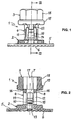
- the fastening element 1 shown in the drawing is made in one piece from plastic made and includes a clamping element 2 and a clamping sleeve 3.
- the clamping element 2 has a sleeve-shaped portion 4 and one at one end of the Section 4 arranged plate-shaped flange 5 on the flange 5 is on his the side facing away from the section 4 at its outer edge with a sawtooth-like Gearing 6 provided.
- the teeth of the toothing 6 are aligned so that they Contact with an opposing surface increase the rotational resistance in the direction of rotation, in the loosened on a threaded bolt fastener are loosened can.
- the clamping element 2 has a cavity 7 for receiving a threaded bolt on the cavity 7 is formed essentially by a cylindrical bore, which penetrates the section 4 and the flange 5, wherein the central axis of the bore coincides with the longitudinal axis of the clamping element 2.
- Section 4 of the Clamping element 2 forms at its the flange 5 opposite end closed ring 8.
- Between the ring 8 and the flange 5 is the wall of the Section 4 through longitudinal slots 9 in two opposing clamping areas 10 and two opposing connecting portions 11 divided.
- the Connecting areas 11 each have a longitudinal slot 12 in their middle. Through the longitudinal slots 12 of the bending resistance of the connecting portions 11th reduces and facilitates deformation transverse to its longitudinal extent.
- On your Outside are the connecting portions 11 with a flat, convex curvature provided whose apex in the middle between the ends of the connecting portions 11 lies.
- the wall sections of the clamping regions 10 are opposite to the ring 8 End through recesses 13, which are transverse to the longitudinal axis of the fastener 1, separated from the flange 5. This allows the clamping area 10 by external forces acting on them comparatively small size are pressed inward into the cavity 7 under elastic deformation.
- the clamping regions 10 In their initial position shown in Figure 3, the clamping regions 10 in one Angle of about 10 ° to the longitudinal axis obliquely placed outwardly so that their the Flange 5 adjacent ends have a greater distance from each other. hereby the outer sides of the clamping regions 10 form clamping ramps inclined to the longitudinal axis 14, in the assembly of the fastener 1 with the associated inner surfaces the clamping sleeve 3 cooperate.
- the clamping areas 10 sawtooth-shaped ribs 15 whose shape and size to the thread of a adapted with the fastener 1 cooperating mounting bolt are.
- the ribs 15 of the opposite Clamping areas 10 also offset in the longitudinal direction to each other.
- the ring 8 has an outer contour in the form of a hexagonal prism.
- the Clamping sleeve 3 has a central opening 17, which also takes the form of a hexagonal Prism has and whose size is adapted to the size of the ring 8 such that the Ring 8 penetrate without appreciable resistance in the opening 17 and while maintaining its orientation along the opening 17 can be moved.
- the clamping sleeve 3 has a trained as a hexagonal prism section 18, which serves to attach a wrench. To section 18 joins a collar 19.
- the projections 20 form coupling elements, which cooperate with counter-coupling elements on the flange 5.
- the flange 5 in mirror image Arrangement two openings 21 into which the projections 20 penetrate, when the clamping sleeve 3 is brought into the mounting position shown in Fig. 3.
- locking fingers 22 are provided, which are parallel to the longitudinal axis in the direction of the flange 5 extend. At the ends of the locking fingers 22 is on the inside each have a pawl 23.
- the locking fingers 22 are openings 24 assigned in the flange 5.
- the openings 24 are provided with an undercut, by which a shoulder 25 is formed. Will the clamping sleeve 3 in its mounting position brought to the clamping element, so penetrate the ends of the locking fingers 22 in the openings 24 and the pawl 23 get into a position in they have their shoulders behind them. As a result, the clamping sleeve 3 in the mounting position held on the clamping element 2.
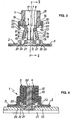
- the fastener 1 is in its mounting position on a threaded bolt 30 shown.
- the threaded bolt 30 is attached to a component 31 and extends through a bore in a second, resting on the component 31 Component 32 in the fastener 1 inside.
- the fastener 1 lies with the toothing 6 of the flange 5 directly on the component 32 and presses this to the component 31 at.
- the fastener 1 is in this case on the threaded bolt 30 supported by means of the clamping portions 10, with their ribs 15 in the thread grooves engage the bolt thread and in this position by the on the clamping area 10 deferred clamping sleeve 3 are fixed.
- the mounting position of the fastening element 1 shown in Figure 4 is the following First, the fastener 1 will be in the initial one in the state shown in Figures 1 to 3 pushed onto the threaded bolt 30, what is possible without significant resistance, since the cavity 7 sized so large is that neither the clamping portion 10 nor the connecting portion 11 when plugging must be deformed radially outward on the threaded bolt 30. Should a mounting on a bottom of a component done, it can however be expedient, the distance between at least two opposite ribs 15 of the clamping regions 10 already initially slightly smaller than the outer diameter of the threaded bolt, so that the fastening element 1 after plugging is held on the threaded bolt 30.
- the predetermined breaking points 16 through a force acting on the clamping sleeve and directed against the component 32 axial force, for example, generated by a blow with a hammer, to be broken and the clamping sleeve 3 can be moved to rest on the flange 5.
- the clamping element 2 penetrates into the opening 17 of the clamping sleeve 3 and the with the clamping ramps 14 cooperating inner surfaces of the opening 17 press the clamping portions 10 into the cavity 7 and fixed to the threaded bolt 30th on, wherein the ribs 15 engage in the grooves of the bolt thread.
- the connecting portions 11 also through the inner surfaces of the Opening 17 are bent radially inwardly in its central region, so that they without play and with preload on the threads of the bolt thread.
- the projections 20 engage with the openings 21 and the locking fingers 22 penetrate into the openings 24, wherein the pawl 23 in the Snap undercut behind shoulders 25.
Landscapes
- Engineering & Computer Science (AREA)
- General Engineering & Computer Science (AREA)
- Mechanical Engineering (AREA)
- Clamps And Clips (AREA)
- Connection Of Plates (AREA)
Abstract
Description
- Figur 1
- eine Seitenansicht eines erfindungsgemäßen Befestigungselements,
- Figur 2
- einen Längsschnitt durch das erfindungsgemäße Befestigungselement entlang der Linie II - II in Figur 3,
- Figur 3
- einen Längsschnitt durch das erfindungsgemäße Befestigungselement entlang der Linie III - III in Figur 1,
- Figur 4
- einen Längsschnitt des Befestigungselementes in montiertem Zustand.
Claims (10)
- Befestigungselement zur Anbringung auf einem Gewindebolzen mit einem hülsenartigen Klemmelement, das einen sich in Richtung seiner Längsachse erstreckenden Hohlraum zur Aufnahme des Gewindebolzens und wenigstens einen in den Hohlraum hinein verformbaren Klemmbereich aufweist, der auf der Außenseite des Klemmelementes wenigstens eine zur Längsachse geneigte Klemmrampe bildet, und mit einer Spannhülse, die auf das Klemmelement aufschiebbar ist und im montierten Zustand das Klemmelement umgreift, wobei eine Innenfläche der Spannhülse mit der Klemmrampe derart zusammenwirkt, daß der Klemmbereich in eine in den Hohlraum verformte, den Gewindekörper festhaltende Klemmstellung gelangt, wobei das Klemmelement an seinem in Montagerichtung vorderen Ende einen Flansch aufweist, dadurch gekennzeichnet, daß an dem Flansch (5) einerseits und an dem dem Flansch zugekehrte Ende der Spannhülse (3) andererseits Kupplungselemente und Gegenkupplungselemente angeordnet sind, die ineinandergreifen und eine Drehung der Spannhülse (3) relativ zum Klemmelement (2) verhindern, wenn sich die Spannhülse (3) im montierten Zustand auf dem Klemmelement (2) befindet.
- Befestigungselement nach Anspruch 1, dadurch gekennzeichnet, daß die Kupplungselemente durch axiale Vorsprünge (20) an der Stirnfläche der Spannhülse (3) und die Gegenkupplungselemente durch die Vorsprünge (20) aufnehmende Ausnehmungen (21) im Flansch (5) des Klemmelementes (2) gebildet sind.
- Befestigungselement nach einem der vorhergehenden Ansprüche, dadurch gekennzeichnet, daß der anfängliche Innendurchmesser des Hohlraumes (7) gleich oder größer ist als der Außendurchmesser des Gewindebolzens (30).
- Befestigungselement nach einem der vorhergehenden Ansprüche, dadurch gekennzeichnet, daß der Klemmbereich (10) des Klemmelementes (2) auf der mit dem Gewindebolzen (30) zusammenwirkenden Innenseite wenigstens eine Rippe (15) aufweist, die dazu ausgebildet ist, in eine Gewinderille des Gewindebolzens (30) einzugreifen.
- Befestigungselement nach einem der vorhergehenden Ansprüche, dadurch gekennzeichnet, daß der Flansch (5) auf seiner vom Klemmelement (2) abgekehrten Seite eine mit einer Verzahnung (6) versehene Anlagefläche hat.
- Befestigungselement nach einem der vorhergehenden Ansprüche, dadurch gekennzeichnet, daß an der Spannhülse (3) wenigstens ein sich in Richtung des Flansches (5) erstreckender, flexibler Verriegelungsfinger (22) vorgesehen, der an seinem Ende einen eine Schulter (25) des Klemmelementes (2) hintergreifenden Sperrhaken (23) trägt.
- Befestigungselement nach Anspruch 6, dadurch gekennzeichnet, daß der Flansch (5) des Klemmelementes (2) eine mit dem Sperrhaken (23) zusammenwirkende Öffnung (24) mit einer durch einen Hinterschnitt gebildeten Schulter (25) aufweist.
- Befestigungselement nach einem der vorhergehenden Ansprüche, dadurch gekennzeichnet, daß die Spannhülse (2) in einer für die Montage geeigneten Ausgangsstellung durch eine Sollbruchstelle (16) einstückig mit dem Klemmelement (2) verbunden ist.
- Befestigungselement nach Anspruch 8, dadurch gekennzeichnet, daß die Sollbruchstelle () zwischen dem in Montagerichtung hinteren Ende des Klemmelementes (2) und dem vorderen Ende der Spannhülse (3) vorgesehen ist.
- Befestigungselement nach einem der vorhergehenden Ansprüche, dadurch gekennzeichnet, daß das Klemmelement (2) eine polygonale Außenfläche und die Spannhülse (3) eine mit dieser zusammenwirkende polygonale Innenfläche hat.
Applications Claiming Priority (2)
| Application Number | Priority Date | Filing Date | Title |
|---|---|---|---|
| DE10357024A DE10357024A1 (de) | 2003-12-03 | 2003-12-03 | Befestigungselement zur Anbringung auf einem Gewindebolzen |
| DE10357024 | 2003-12-03 |
Publications (2)
| Publication Number | Publication Date |
|---|---|
| EP1538350A1 true EP1538350A1 (de) | 2005-06-08 |
| EP1538350B1 EP1538350B1 (de) | 2007-02-28 |
Family
ID=34442476
Family Applications (1)
| Application Number | Title | Priority Date | Filing Date |
|---|---|---|---|
| EP04028388A Expired - Lifetime EP1538350B1 (de) | 2003-12-03 | 2004-12-01 | Befestigungselement zur Anbringung auf einem Gewindebolzen |
Country Status (5)
| Country | Link |
|---|---|
| US (2) | US7179038B2 (de) |
| EP (1) | EP1538350B1 (de) |
| JP (1) | JP2005172237A (de) |
| DE (2) | DE10357024A1 (de) |
| ES (1) | ES2281738T3 (de) |
Cited By (6)
| Publication number | Priority date | Publication date | Assignee | Title |
|---|---|---|---|---|
| WO2009086877A1 (de) | 2008-01-10 | 2009-07-16 | A. Raymond Et Cie | Eingriffseinheit zum aufstecken und zum eingriff mit einem gewindebolzen |
| EP2250382A4 (de) * | 2008-03-06 | 2013-07-10 | Newfrey Llc | Befestiger für fahrzeugkomponenten |
| EP3339664A1 (de) * | 2016-12-21 | 2018-06-27 | Newfrey LLC | Befestigungselement, anordnung mit einem befestigungselement und einbauverfahren eines befestigungselements |
| EP3392418A1 (de) * | 2017-04-19 | 2018-10-24 | Geberit International AG | Befestigungssystem |
| EP3683458A1 (de) | 2019-01-21 | 2020-07-22 | A. Raymond et Cie | Befestigungsvorrichtung mit mehreren stiften, die eine spannung erzeugt, und befestigungsverfahren einer solchen vorrichtung |
| CN116537428A (zh) * | 2023-05-23 | 2023-08-04 | 中国十九冶集团有限公司 | 用于钢结构建筑的组合式楼承板施工结构 |
Families Citing this family (31)
| Publication number | Priority date | Publication date | Assignee | Title |
|---|---|---|---|---|
| DE10357024A1 (de) * | 2003-12-03 | 2005-06-30 | Newfrey Llc, Newark | Befestigungselement zur Anbringung auf einem Gewindebolzen |
| DE102004061087B4 (de) * | 2004-12-18 | 2006-12-07 | A. Raymond Et Cie | Vorrichtung zum Befestigen eines Anbauteiles und eines Trägerteiles in einem Abstand voneinander |
| US7338242B2 (en) * | 2005-11-28 | 2008-03-04 | Ellis Gary L | Quick-connect fastener assembly |
| JP4850573B2 (ja) * | 2006-04-24 | 2012-01-11 | ポップリベット・ファスナー株式会社 | アンダーカバー等の固定具及び取付装置 |
| US20100043173A1 (en) * | 2008-08-20 | 2010-02-25 | Geoffrey Barr | Adjustable upstop for frameless automotive door |
| US7871102B2 (en) * | 2008-09-16 | 2011-01-18 | Newfrey Llc | Air bag fastener assembly |
| US8245448B2 (en) * | 2008-12-30 | 2012-08-21 | Rubber Development Inc. | Door plug |
| US8231318B2 (en) * | 2009-04-22 | 2012-07-31 | As Ip Holdco, L.L.C. | Push and turn nut for quick faucet installation |
| US8959730B2 (en) * | 2009-09-24 | 2015-02-24 | A. Raymond Et Cie | Push-on clip fastener |
| CA2781763C (en) * | 2009-10-27 | 2015-01-06 | Handy & Harman | Self-drilling bolt and nut assembly |
| CN102384137A (zh) * | 2010-09-01 | 2012-03-21 | 鸿富锦精密工业(深圳)有限公司 | 接头装置 |
| DE102011010036A1 (de) * | 2011-01-24 | 2012-07-26 | Illinois Tool Works Inc. | Vorrichtung zur Befestigung eines Bauteils an einem Trägerbauteil |
| US9376789B2 (en) | 2011-03-08 | 2016-06-28 | As Ip Holdco, Llc | Quick connection coupling |
| WO2012166552A1 (en) | 2011-06-02 | 2012-12-06 | A. Raymond Et Cie | Fasteners manufactured by three-dimensional printing |
| WO2013029023A1 (en) | 2011-08-24 | 2013-02-28 | As Ip Holdco, L.L.C. | No-tools spread faucet assembly, kits and methods |
| US9174590B2 (en) | 2012-04-17 | 2015-11-03 | Newfrey Llc | Fascia bracket mounting system—captive floating nut system to weld stud |
| US9199437B2 (en) * | 2012-04-18 | 2015-12-01 | GM Global Technology Operations LLC | Panel assembly retainer and method of use |
| US8800120B2 (en) | 2012-04-27 | 2014-08-12 | Newfrey Llc | High retention fastener |
| DE102012022239A1 (de) * | 2012-11-14 | 2014-05-15 | Daimler Ag | Bauteil zur Befestigung an einem Trägerbauteil eines Automobils |
| US10851583B2 (en) * | 2015-08-21 | 2020-12-01 | Isaac Ben Ezra | Accessory for preventing a pre-hung door from sagging in a door frame |
| US10682160B2 (en) | 2015-12-03 | 2020-06-16 | Globus Medical, Inc. | External fixator assembly |
| US10136919B2 (en) * | 2015-12-03 | 2018-11-27 | Globus Medical, Inc. | External fixator assembly |
| US9943337B2 (en) | 2015-12-03 | 2018-04-17 | Globus Medical, Inc. | External fixator assembly |
| US9872707B2 (en) | 2015-12-03 | 2018-01-23 | Globus Medical, Inc. | External fixator assembly |
| US10378257B2 (en) * | 2017-07-26 | 2019-08-13 | Fca Us Llc | Nut for threaded hinge pin |
| DE102017126135A1 (de) * | 2017-11-08 | 2019-05-09 | BPW-Hungária Kft. | Vorrichtung zur Lasterfassung von vorzugsweise Druck-, Zug- und/oder Torsionsbelastungen an einem Nutzfahrzeug-Fahrwerksteil |
| US10945765B2 (en) * | 2017-12-06 | 2021-03-16 | Austin Miller Trauma LLC | Fixation clamp with spacer |
| DE102018104360A1 (de) * | 2018-02-27 | 2019-08-29 | Airbus Operations Gmbh | Befestigungssystem zum Sichern von Bauteilen |
| CA3044632A1 (en) * | 2019-05-29 | 2020-11-29 | Gordian Enterprises Inc. | Split nut |
| DE102019121911A1 (de) * | 2019-08-14 | 2021-02-18 | Illinois Tool Works Inc. | Bolzenbefestigung |
| US12435749B2 (en) * | 2020-12-03 | 2025-10-07 | Compass Manufacturing International, Llc | Adjustable nut for faucet installation |
Citations (2)
| Publication number | Priority date | Publication date | Assignee | Title |
|---|---|---|---|---|
| DE3503293A1 (de) * | 1984-01-31 | 1985-08-01 | USM Corp., Farmington, Conn. | Befestigungsteil |
| DE10133063A1 (de) * | 2001-07-07 | 2003-01-30 | Itw Automotive Prod Gmbh & Co | Befestigungsvorrichtung |
Family Cites Families (37)
| Publication number | Priority date | Publication date | Assignee | Title |
|---|---|---|---|---|
| US750675A (en) * | 1904-01-26 | mighelin | ||
| US1390564A (en) * | 1920-01-24 | 1921-09-13 | Margaret R Elkin | Hose-clamp |
| US1475907A (en) * | 1922-04-08 | 1923-11-27 | Volman Ani | Securing element |
| US2367480A (en) * | 1939-08-14 | 1945-01-16 | Beswick Robert Eardley | Nut for quick attachment |
| US2404169A (en) * | 1945-08-14 | 1946-07-16 | Norman L Gidden | Fastener |
| US2868564A (en) * | 1957-11-13 | 1959-01-13 | Arras Damiano | Hose connector with axially sliding locking sleeve |
| JPS4830770Y1 (de) * | 1969-05-21 | 1973-09-19 | ||
| US3921496A (en) * | 1974-11-04 | 1975-11-25 | J Frank Helderman | Fastener assembly |
| NL169513C (nl) * | 1978-01-13 | 1982-07-16 | Nedschroef Octrooi Maats | Zelfborgend bevestigingselement respectievelijk een stempel voor het maken van dat element. |
| JPS5621618U (de) * | 1979-07-29 | 1981-02-26 | ||
| JPS602334Y2 (ja) * | 1980-07-15 | 1985-01-23 | 株式会社ニフコ | ナツト |
| US4460298A (en) * | 1981-06-03 | 1984-07-17 | Illinois Tool Works Inc. | Self retaining threaded screw grommet |
| US4659273A (en) * | 1985-11-08 | 1987-04-21 | Trailer Marine Transport | Lug attachment |
| JPH0353046Y2 (de) * | 1987-01-23 | 1991-11-19 | ||
| US4812095A (en) * | 1987-02-24 | 1989-03-14 | Emhart Industries, Inc. | Threaded fastener |
| US4781504A (en) * | 1987-05-21 | 1988-11-01 | Emhart Industries, Inc. | Trim clip |
| JPH0422088Y2 (de) * | 1987-08-07 | 1992-05-20 | ||
| DE3739443C2 (de) * | 1987-11-20 | 1994-03-31 | United Carr Gmbh Trw | Kunststoffteil zur Halterung eines Gewindebolzens |
| US4850778A (en) * | 1988-07-27 | 1989-07-25 | Trw, Inc. | Push-on fastener |
| JP2533676B2 (ja) | 1990-07-25 | 1996-09-11 | 松下電工株式会社 | ノンタッチスイッチ装置 |
| US5183359A (en) * | 1992-05-12 | 1993-02-02 | Illinois Tool Works Inc. | Rotary fastener with anti-strip-out nibs |
| JPH0645053Y2 (ja) * | 1992-10-27 | 1994-11-16 | 協永産業株式会社 | 締結具のキャップ |
| BR7400587U (pt) * | 1994-03-24 | 1994-10-04 | Seabra Helio Lanfranchi | Aperfeiçoamento introduzido no processo de fabricação de luva de conexão para tubos |
| JPH08159118A (ja) | 1994-12-12 | 1996-06-18 | Pop Rivet Fastener Kk | シート状部材の保持具 |
| JP3319566B2 (ja) * | 1995-03-31 | 2002-09-03 | 株式会社イナックス | 連結用クリップ |
| US5816762A (en) * | 1996-07-09 | 1998-10-06 | Illinois Tool Works Inc. | Stud clip having different insertion/withdrawal forces |
| JP4063907B2 (ja) * | 1997-01-20 | 2008-03-19 | ポップリベット・ファスナー株式会社 | 押込み式ナット |
| JP3938615B2 (ja) * | 1997-06-24 | 2007-06-27 | ポップリベット・ファスナー株式会社 | 押し込み式ナット |
| DE29711251U1 (de) * | 1997-06-27 | 1998-11-12 | Emhart Inc., Newark, Del. | Halter aus Kunststoff mit verschwenkbaren Halteelementen |
| FR2776747B1 (fr) * | 1998-03-27 | 2000-06-02 | Hutchinson | Raccord encliquetable pour tuyau de transfert de fluide |
| JP2001317515A (ja) * | 2000-05-11 | 2001-11-16 | Nippon Pop Rivets & Fasteners Ltd | 保持具 |
| US6318940B1 (en) * | 2000-06-21 | 2001-11-20 | Illinois Tool Works Inc. | Fastener for self-locking securement within a panel opening |
| US6343904B1 (en) * | 2000-11-15 | 2002-02-05 | Hexico Enterprise Co., Ltd. | Fastener assembly for preventing corotation during tightening |
| JP2002250324A (ja) * | 2001-02-21 | 2002-09-06 | Mitsumi Electric Co Ltd | ナット |
| US6796586B2 (en) * | 2001-07-09 | 2004-09-28 | Twin Bay Medical, Inc. | Barb clamp |
| WO2003089797A2 (en) * | 2002-04-16 | 2003-10-30 | Werth Albert A | Barb clamp |
| DE10357024A1 (de) * | 2003-12-03 | 2005-06-30 | Newfrey Llc, Newark | Befestigungselement zur Anbringung auf einem Gewindebolzen |
-
2003
- 2003-12-03 DE DE10357024A patent/DE10357024A1/de not_active Withdrawn
-
2004
- 2004-11-19 US US10/994,210 patent/US7179038B2/en not_active Expired - Fee Related
- 2004-12-01 JP JP2004348267A patent/JP2005172237A/ja active Pending
- 2004-12-01 EP EP04028388A patent/EP1538350B1/de not_active Expired - Lifetime
- 2004-12-01 DE DE502004003025T patent/DE502004003025D1/de not_active Expired - Lifetime
- 2004-12-01 ES ES04028388T patent/ES2281738T3/es not_active Expired - Lifetime
-
2007
- 2007-02-06 US US11/703,047 patent/US20070160441A1/en not_active Abandoned
Patent Citations (2)
| Publication number | Priority date | Publication date | Assignee | Title |
|---|---|---|---|---|
| DE3503293A1 (de) * | 1984-01-31 | 1985-08-01 | USM Corp., Farmington, Conn. | Befestigungsteil |
| DE10133063A1 (de) * | 2001-07-07 | 2003-01-30 | Itw Automotive Prod Gmbh & Co | Befestigungsvorrichtung |
Cited By (12)
| Publication number | Priority date | Publication date | Assignee | Title |
|---|---|---|---|---|
| WO2009086877A1 (de) | 2008-01-10 | 2009-07-16 | A. Raymond Et Cie | Eingriffseinheit zum aufstecken und zum eingriff mit einem gewindebolzen |
| US8348578B2 (en) | 2008-01-10 | 2013-01-08 | A. Raymond Et Cie | Engagement unit for attaching and for engaging a threaded bolt |
| CN101910652B (zh) * | 2008-01-10 | 2014-08-06 | A·雷蒙德公司 | 用于套置并与螺栓啮合的啮合单元 |
| EP2250382A4 (de) * | 2008-03-06 | 2013-07-10 | Newfrey Llc | Befestiger für fahrzeugkomponenten |
| EP3339664A1 (de) * | 2016-12-21 | 2018-06-27 | Newfrey LLC | Befestigungselement, anordnung mit einem befestigungselement und einbauverfahren eines befestigungselements |
| EP3392418A1 (de) * | 2017-04-19 | 2018-10-24 | Geberit International AG | Befestigungssystem |
| EP3392419A1 (de) * | 2017-04-19 | 2018-10-24 | Geberit International AG | Befestigungssystem |
| CN108730302A (zh) * | 2017-04-19 | 2018-11-02 | 吉博力国际股份公司 | 固定系统 |
| CN108730302B (zh) * | 2017-04-19 | 2021-09-07 | 吉博力国际股份公司 | 固定系统 |
| EP3683458A1 (de) | 2019-01-21 | 2020-07-22 | A. Raymond et Cie | Befestigungsvorrichtung mit mehreren stiften, die eine spannung erzeugt, und befestigungsverfahren einer solchen vorrichtung |
| FR3091909A1 (fr) * | 2019-01-21 | 2020-07-24 | A. Raymond Et Cie | Dispositif de fixation multigoujon generant une mise sous tension, et procede de fixation d’un tel dispositif |
| CN116537428A (zh) * | 2023-05-23 | 2023-08-04 | 中国十九冶集团有限公司 | 用于钢结构建筑的组合式楼承板施工结构 |
Also Published As
| Publication number | Publication date |
|---|---|
| US20070160441A1 (en) | 2007-07-12 |
| US7179038B2 (en) | 2007-02-20 |
| DE502004003025D1 (de) | 2007-04-12 |
| DE10357024A1 (de) | 2005-06-30 |
| EP1538350B1 (de) | 2007-02-28 |
| JP2005172237A (ja) | 2005-06-30 |
| ES2281738T3 (es) | 2007-10-01 |
| US20050135901A1 (en) | 2005-06-23 |
Similar Documents
| Publication | Publication Date | Title |
|---|---|---|
| EP1538350B1 (de) | Befestigungselement zur Anbringung auf einem Gewindebolzen | |
| DE102010051372B4 (de) | Verbindungselement mit integrierter Schnappverbindung | |
| EP1961976B1 (de) | Befestigungseinheit | |
| DE2813025C2 (de) | Sicherheitsbolzen | |
| DE102014103535B4 (de) | Vorrichtung zur Befestigung eines Bauteils an einem Trägerbauteil | |
| DE102011106696A1 (de) | Schraubelement zum Befestigen einer Leitung an einem Gegenstück | |
| EP0932789B1 (de) | Steckverbindung für rohrleitungen | |
| EP3612740B1 (de) | Verstelleinheit und einstellverfahren für ein bauteil | |
| EP2063136A2 (de) | Verbindungselement mit einer Schraube und einer daran unverlierbar angeordneten Hülse | |
| EP1343974B1 (de) | Verbindereinrichtung für profile | |
| EP0636798B1 (de) | Drehverschluss | |
| EP4095396B1 (de) | Toleranzausgleichsvorrichtung | |
| EP4357627B1 (de) | Toleranzausgleichsvorrichtung | |
| EP2261519A2 (de) | Schraube zum Befestigen eines ersten Bauteils an einem zweiten Bauteil | |
| DE10133063B4 (de) | Befestigungsvorrichtung und Befestigungselement | |
| DE1475035B2 (de) | Befestigungsvorrichtung | |
| EP3565979B1 (de) | Befestigungsanordnung und ein entsprechendes schaltschrankgehäuse | |
| DE10253888B4 (de) | Befestigungseinheit | |
| WO2006103265A1 (de) | Befestigungselement zur anbringung auf einem gewindebolzen | |
| EP0267161B1 (de) | Schraubvorrichtung | |
| DE4213862C2 (de) | Blindnietartiger Klemmverbinder | |
| DE2142488A1 (de) | Lösbarer Schraubverbinddr, insbesondere zum Anschluß von Tafeln an Rahmen od. dgl | |
| DE102017116057B4 (de) | Befestigungsbaugruppe | |
| DE19912068B4 (de) | Wellen- oder Stellmutter und Verfahren zu ihrer Herstellung | |
| DE102019129531A1 (de) | Befestigungselement |
Legal Events
| Date | Code | Title | Description |
|---|---|---|---|
| PUAI | Public reference made under article 153(3) epc to a published international application that has entered the european phase |
Free format text: ORIGINAL CODE: 0009012 |
|
| AK | Designated contracting states |
Kind code of ref document: A1 Designated state(s): AT BE BG CH CY CZ DE DK EE ES FI FR GB GR HU IE IS IT LI LT LU MC NL PL PT RO SE SI SK TR |
|
| AX | Request for extension of the european patent |
Extension state: AL BA HR LV MK YU |
|
| 17P | Request for examination filed |
Effective date: 20051206 |
|
| AKX | Designation fees paid |
Designated state(s): CZ DE ES |
|
| GRAP | Despatch of communication of intention to grant a patent |
Free format text: ORIGINAL CODE: EPIDOSNIGR1 |
|
| GRAS | Grant fee paid |
Free format text: ORIGINAL CODE: EPIDOSNIGR3 |
|
| GRAA | (expected) grant |
Free format text: ORIGINAL CODE: 0009210 |
|
| AK | Designated contracting states |
Kind code of ref document: B1 Designated state(s): CZ DE ES |
|
| REF | Corresponds to: |
Ref document number: 502004003025 Country of ref document: DE Date of ref document: 20070412 Kind code of ref document: P |
|
| REG | Reference to a national code |
Ref country code: ES Ref legal event code: FG2A Ref document number: 2281738 Country of ref document: ES Kind code of ref document: T3 |
|
| PLBE | No opposition filed within time limit |
Free format text: ORIGINAL CODE: 0009261 |
|
| STAA | Information on the status of an ep patent application or granted ep patent |
Free format text: STATUS: NO OPPOSITION FILED WITHIN TIME LIMIT |
|
| 26N | No opposition filed |
Effective date: 20071129 |
|
| PGFP | Annual fee paid to national office [announced via postgrant information from national office to epo] |
Ref country code: CZ Payment date: 20131128 Year of fee payment: 10 |
|
| PGFP | Annual fee paid to national office [announced via postgrant information from national office to epo] |
Ref country code: ES Payment date: 20141226 Year of fee payment: 11 |
|
| PG25 | Lapsed in a contracting state [announced via postgrant information from national office to epo] |
Ref country code: CZ Free format text: LAPSE BECAUSE OF NON-PAYMENT OF DUE FEES Effective date: 20141201 |
|
| REG | Reference to a national code |
Ref country code: ES Ref legal event code: FD2A Effective date: 20170127 |
|
| PGFP | Annual fee paid to national office [announced via postgrant information from national office to epo] |
Ref country code: DE Payment date: 20161123 Year of fee payment: 13 |
|
| PG25 | Lapsed in a contracting state [announced via postgrant information from national office to epo] |
Ref country code: ES Free format text: LAPSE BECAUSE OF NON-PAYMENT OF DUE FEES Effective date: 20151202 |
|
| REG | Reference to a national code |
Ref country code: DE Ref legal event code: R119 Ref document number: 502004003025 Country of ref document: DE |
|
| PG25 | Lapsed in a contracting state [announced via postgrant information from national office to epo] |
Ref country code: DE Free format text: LAPSE BECAUSE OF NON-PAYMENT OF DUE FEES Effective date: 20180703 |