EP1538327B1 - Culasse avec chemise de refroidissement qui contient un noyau de coulée et conduit d'aération - Google Patents
Culasse avec chemise de refroidissement qui contient un noyau de coulée et conduit d'aération Download PDFInfo
- Publication number
- EP1538327B1 EP1538327B1 EP20030104538 EP03104538A EP1538327B1 EP 1538327 B1 EP1538327 B1 EP 1538327B1 EP 20030104538 EP20030104538 EP 20030104538 EP 03104538 A EP03104538 A EP 03104538A EP 1538327 B1 EP1538327 B1 EP 1538327B1
- Authority
- EP
- European Patent Office
- Prior art keywords
- cylinder head
- angle
- coolant
- cooling
- cooling jacket
- Prior art date
- Legal status (The legal status is an assumption and is not a legal conclusion. Google has not performed a legal analysis and makes no representation as to the accuracy of the status listed.)
- Expired - Lifetime
Links
- 238000001816 cooling Methods 0.000 title claims description 74
- 238000013022 venting Methods 0.000 title description 8
- 239000002826 coolant Substances 0.000 claims description 62
- 238000002485 combustion reaction Methods 0.000 claims description 21
- 238000009423 ventilation Methods 0.000 claims description 14
- 238000005266 casting Methods 0.000 claims description 8
- 238000009434 installation Methods 0.000 description 14
- 239000007789 gas Substances 0.000 description 9
- 239000007788 liquid Substances 0.000 description 8
- 238000012546 transfer Methods 0.000 description 8
- 230000006378 damage Effects 0.000 description 4
- 238000000034 method Methods 0.000 description 4
- 238000013021 overheating Methods 0.000 description 4
- 238000010521 absorption reaction Methods 0.000 description 3
- 230000000694 effects Effects 0.000 description 3
- 239000000446 fuel Substances 0.000 description 3
- XLYOFNOQVPJJNP-UHFFFAOYSA-N water Substances O XLYOFNOQVPJJNP-UHFFFAOYSA-N 0.000 description 3
- 239000000654 additive Substances 0.000 description 2
- 238000001704 evaporation Methods 0.000 description 2
- 230000008020 evaporation Effects 0.000 description 2
- 230000017525 heat dissipation Effects 0.000 description 2
- 239000003110 molding sand Substances 0.000 description 2
- 230000004888 barrier function Effects 0.000 description 1
- 230000015572 biosynthetic process Effects 0.000 description 1
- 238000009835 boiling Methods 0.000 description 1
- 238000006243 chemical reaction Methods 0.000 description 1
- 238000010276 construction Methods 0.000 description 1
- 230000007423 decrease Effects 0.000 description 1
- 238000013461 design Methods 0.000 description 1
- 230000001627 detrimental effect Effects 0.000 description 1
- 239000012634 fragment Substances 0.000 description 1
- 238000007710 freezing Methods 0.000 description 1
- 230000008014 freezing Effects 0.000 description 1
- 229930195733 hydrocarbon Natural products 0.000 description 1
- 150000002430 hydrocarbons Chemical class 0.000 description 1
- 238000002156 mixing Methods 0.000 description 1
- 230000002093 peripheral effect Effects 0.000 description 1
- 230000005855 radiation Effects 0.000 description 1
- 230000000630 rising effect Effects 0.000 description 1
- 239000000126 substance Substances 0.000 description 1
Images






Classifications
-
- F—MECHANICAL ENGINEERING; LIGHTING; HEATING; WEAPONS; BLASTING
- F02—COMBUSTION ENGINES; HOT-GAS OR COMBUSTION-PRODUCT ENGINE PLANTS
- F02F—CYLINDERS, PISTONS OR CASINGS, FOR COMBUSTION ENGINES; ARRANGEMENTS OF SEALINGS IN COMBUSTION ENGINES
- F02F1/00—Cylinders; Cylinder heads
- F02F1/24—Cylinder heads
- F02F1/26—Cylinder heads having cooling means
- F02F1/36—Cylinder heads having cooling means for liquid cooling
- F02F1/40—Cylinder heads having cooling means for liquid cooling cylinder heads with means for directing, guiding, or distributing liquid stream
-
- F—MECHANICAL ENGINEERING; LIGHTING; HEATING; WEAPONS; BLASTING
- F01—MACHINES OR ENGINES IN GENERAL; ENGINE PLANTS IN GENERAL; STEAM ENGINES
- F01P—COOLING OF MACHINES OR ENGINES IN GENERAL; COOLING OF INTERNAL-COMBUSTION ENGINES
- F01P11/00—Component parts, details, or accessories not provided for in, or of interest apart from, groups F01P1/00 - F01P9/00
- F01P11/02—Liquid-coolant filling, overflow, venting, or draining devices
- F01P11/028—Deaeration devices
Definitions
- the invention relates to a cylinder head of an internal combustion engine having a coolant jacket, comprising a one-piece cooling jacket core and at least one vent strip.
- the heat released during combustion by the exothermic, chemical conversion of the fuel is partly dissipated via the walls delimiting the combustion chamber to the cylinder head and the cylinder block and partly via the exhaust gas flow to the adjacent components and the environment.
- a portion of the introduced into the cylinder head heat flow must be withdrawn from the cylinder head again.
- the amount of heat dissipated from the surface of the internal combustion engine via radiation and heat conduction to the environment is not sufficient for efficient cooling, which is why cooling of the cylinder head is usually brought about deliberately by means of forced convection.
- the cooling in the form of air cooling or liquid cooling.
- the internal combustion engine is provided with a fan, wherein the heat removal takes place by means of air flows guided over the surface of the cylinder head.
- the liquid cooling requires the equipment of the internal combustion engine or the cylinder head with a coolant jacket ie the arrangement of the coolant through the cylinder head leading coolant channels, resulting in a very complex structure of the cylinder head construction.
- the mechanically and thermally highly stressed cylinder head is weakened by the introduction of the coolant channels on the one hand in its strength.
- the heat must not be directed to the cylinder head surface, as in air cooling to be dissipated.
- the heat is already in the interior of the cylinder head to the coolant, usually mixed with additives added water.
- the coolant is thereby conveyed by means of a pump arranged in the cooling circuit, so that it circulates in the coolant jacket.
- the heat given off to the coolant is removed in this way from the interior of the cylinder head and removed from the coolant in a heat exchanger again.
- liquid cooling is of much greater relevance than air cooling because the thermal load is high on supercharged engines compared to conventional ones
- Internal combustion engines larger The charge is primarily a method of increasing performance, in which the air required for the engine combustion process air is compressed, so that per working cycle a larger mass of air enters the combustion chamber. As a result, the fuel mass can be increased. With targeted design of the charge also advantages in efficiency and exhaust emissions can be achieved.
- liquid cooling or a cylinder head with a coolant jacket which has a one-piece cooling jacket core and at least one vent strip, the subject of the present invention.
- the cooling jacket core is intended to be formed in one piece in contrast to the two-part or multi-part cooling jacket cores, in which the coolant space is divided by the arrangement of an intermediate wall in a first and a second coolant space and optionally in other coolant spaces that may communicate with each other.
- Multi-part cooling jacket cores tend to have a larger volume of coolant, which is why the warm-up phase of the internal combustion engine takes more time after a cold start, causing the Engine reaches its operating temperature later and the emissions, especially the unburned hydrocarbons, and fuel consumption are higher.
- cooling jacket core is understood to mean the part of the coolant jacket in which the coolant circulates in the cylinder head for heat absorption, whereas the vent strip absorbs heat from the cylinder head, but primarily serves to remove air and vapor bubbles from the cooling circuit ,
- the main function of the vent strip is therefore - unlike the cooling jacket core - not the heat, but the venting of the coolant jacket.
- a ventilation device or vent strip is an essential and indispensable component of the coolant jacket. There are essentially two reasons for this.
- air can enter the coolant circuit from the outside.
- the coolant circuit For example, in the filling of the coolant circuit with coolant or the mixing of additives to reduce the freezing point of the coolant, which is usually done to make the engine suitable for winter, inadvertently air penetrate into the cooling circuit. But even in leaky cooling circuits, for example in porous coolant hoses, air can penetrate.
- air in the cooling circuit can cause engine damage d. H. lead to the destruction of the entire internal combustion engine, namely, when an air bubble in the coolant pump, which is to be provided for the promotion of the coolant forms, and the coolant pump begins to promote air, d. H. no coolant is pumped through the cooling circuit.
- the coolant pump so to speak, the promotion, so that the coolant circulation comes to a standstill and the coolant and ultimately the internal combustion engine is overheated for lack of heat dissipation and thermally overloaded.
- air Due to their low heat capacity, air can absorb much less heat than a liquid d. H. as the coolant. On the other hand, the heat absorbed within the air bubbles due to the poor heat transfer properties of air is insufficiently forwarded. In addition, air has a lower heat transfer coefficient than a liquid, which is why the air forms a barrier, as it were, by which the heat transfer from the cylinder head or cylinder block is deteriorated to the cooling jacket. The air collecting at local maxima, which lingers at these points for a long time, can lead to local overheating at these points - so-called hot spots. In addition to the low heat capacity, the low heat transfer coefficient and the poor heat conduction properties of air is mainly responsible for the lack of flow due to convection.
- a ventilation device is required not only for the air that has penetrated into the system but also for the coolant vapor bubbles forming in the system or their removal.
- the superheated coolant evaporates, during the boiling process on the cooling jacket wall, first of all the heat transfer from the cylinder head to the coolant increases, before the heat transfer then decreases, ie worsens, as a result of the lower heat conduction coefficient and the lower heat capacity of the vapor.
- At locations local cooling channel maxima often form dead water areas in which the coolant flow comes to a standstill, thus no heat transfer by convection is given more and in evaporation of the coolant overheating of the cylinder head - so-called hot spots - are to be feared.
- the local maxima in the cooling circuit are to be considered very critical both with regard to the air in circulation as well as with regard to the forming vapor bubbles, since the bubbles collecting here can not be removed due to the lack of or too weak coolant flow.
- FIG. 1 is shown in a perspective view of the coolant jacket (2) of a conventional cylinder head according to the prior art.
- the coolant jacket (2) comprises a cooling jacket core (3), the actual coolant circuit for heat absorption and removal from the cylinder head, and a vent strip (4) for the removal of air and vapor bubbles from the coolant circuit.
- the illustrated cooling jacket (3) is to some extent an image of thedemantelsandkerns the mold of the cylinder head.
- the cooling circuit has a plurality of local maxima and does not have a configuration which advantageously supports the venting.
- a virtual roof plane (5) laid on top of the cooling jacket core (3) runs parallel or nearly parallel to an imaginary horizontal plane (6) or to the cylinder head floor (7).
- the cylinder head floor forms the underside of the cylinder head.
- the roof level drops in the direction of the vent strip (4), so that local maxima are present and in the cooling circuit located air and vapor bubbles are not dissipated, but remain in the circulation.
- a cylinder head of an internal combustion engine having a coolant jacket, which comprises a one-piece cooling jacket core and at least one vent strip and is characterized in that in the installed position of the cylinder head, in which the cylinder head bottom is inclined with respect to a horizontal plane by an angle ⁇ , a virtual on the cooling jacket core from top-mounted roof level in the direction of at least one vent bar runs horizontally or increases, so that the roof level with the horizontal plane in the installed position forms an angle ⁇ ⁇ 0 °.
- the cylinder head according to the invention thus has a coolant jacket, which ensures an optimized ventilation. Characterized in that rise in the installed position, the uppermost walls of the cooling jacket core in the direction of the vent strip, the discharge of air and vapor bubbles is supported in an advantageous manner.
- the cylinder head according to the invention has its optimized venting. Although then the proportion of the forces acting on the gas bubbles buoyancy forces on the venting process is negligible, but the flow tears the bubbles collecting on the uppermost walls and carries them off, which is not guaranteed with a falling roof level with ⁇ ⁇ 0 °.
- the object underlying the invention is achieved, namely to provide a liquid-cooled cylinder head, which has an optimized vent, with which can reduce the dangers that result from air and vapor bubbles in the cooling circuit.
- the cylinder head according to the invention can also be described in such a way that when the cylinder head floor of the cylinder head is inclined in the installed position relative to a horizontal plane in the manner of an angle ⁇ , that the vent bar comes to lie deeper, a virtual on the Cooling jacket core must be tilted from above laid roof level with respect to the cylinder head floor by an angle ⁇ in the opposite direction, where
- Embodiments of the cylinder head are advantageous in which the roof plane forms an angle ⁇ with the cylinder head bottom with 9 ° ⁇ ⁇ 15 °, preferably with 11 ° ⁇ ⁇ 13 °, where
- This embodiment is advantageous because the cylinder head is often inclined in the installed position relative to a horizontal plane in the manner of an angle ⁇ that the vent bar comes to lie deeper, with 9 ° ⁇ ⁇ 15 ° or 11 ° ⁇ ⁇ 13 ° applies.
- Embodiments of the cylinder head in which the internal combustion engine is an in-line engine, preferably a four-cylinder in-line engine, are advantageous.
- FIG. 1 has already been explained in connection with the description of the prior art.
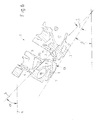
- FIG. 2 is shown in a perspective view of the coolant jacket 2 of a first embodiment of the cylinder head.
- the coolant jacket 2 comprises a one-piece cooling jacket core 3, the actual coolant circuit, for heat absorption and removal from the cylinder head, and designed in the form of a vent strip 4 venting device for the removal of air and vapor bubbles from the coolant circuit.
- FIG. 1 illustrated and already explained conventional cylinder head.
- the cooling jacket 3 is an image of thedemantelsandkerns the mold of the cylinder head.
- two Entkernungsstellen 8 are provided, via which the molding sand is removed after the casting process from the cooled cylinder head blank.
- a virtual roof plane 5 laid on the cooling jacket core 3 from above runs obliquely, ie the roof plane 5 forms an angle ⁇ with the cylinder head bottom 7, which is located in the in-dash FIG. 2 shown position in an imaginary horizontal plane 6 comes to rest.
- the roof level 5 raised from above rises in the direction of at least one vent strip 4, so that the upwardly driven by the buoyancy forces gases that collect in the form of bubbles on the uppermost walls 15 of the cooling jacket core 3, along this uppermost wall 15 to the vent strip 4 are guided and discharged from the cooling circuit.
- the effect is exploited that the buoyancy forces acting on the gas bubbles drive the gases in circulation upwards.
- the cylinder head floor 7 of the cylinder head may be inclined in the installation position relative to a horizontal plane 6 in the manner of an angle ⁇ , that the vent bar 4 comes to lie deeper ie the cylinder head can be rotated counterclockwise without losing the benefits of venting invention go as long as the virtual, on the cooling jacket core 3 from above laid roof level 5 forms an angle ⁇ > 0 ° with the horizontal plane 6 in the installed position.
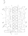
- FIG. 3 shows a fragment of a first embodiment of the cylinder head 1 in a plan view and with a view of the cylinder bottom 7, wherein the cylinder head 1 by the side wall 13 and the two outer walls 14 is limited.
- cylinder head 1 is the cylinder head 1 of a four-cylinder in-line engine, in which the cylinders are arranged along the cylinder head longitudinal axis 16 in a row and each cylinder has two inlet openings 11 and two outlet openings 12.
- FIG. 3 are a total of three sectional planes indicated, which will be discussed further below.
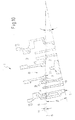
- FIG. 4 shows FIG. 4 the first embodiment of the cylinder head 1 in cross section along the in FIG. 3 indicated section plane II. This section is placed so that it divides a single cylinder in the middle.
- the uppermost walls 15 of the cooling jacket core 3 lie in the virtual roof level 5. These walls 15 collect the air and vapor bubbles in the cooling circuit, which are driven upward by the buoyancy forces acting on them. Furthermore, the bubbles migrate from the coolant flow supported along the top wall 15 in the direction of the vent strip 4, - due to the fact that the roof level 5 rises in the direction of the vent strip 4 - the buoyancy forces exerted by the coolant on the gas bubbles, this venting process support in an advantageous manner.
- the cooling jacket core 3 has in the in FIG. 4 sectional plane II shown a preferred form in which the facing the roof level 5 and lying in the roof level 5 outer walls 15 of the cooling jacket core 3 in the direction of the vent strip 4 steadily increase, so that they have no local maxima in which gas bubbles can catch. The risk of overheating or so-called hot spots is thus reduced to a minimum.
- the angle ⁇ which defines the mounting position and is located between the cylinder head bottom 7 and the horizontal plane 6, is therefore 0 °.
- FIG. 5 and 6 show the first embodiment of the cylinder head 1 in the in FIG. 4 Section II shown in two different installation positions.
- the angle ⁇ which lies between the roof plane 5 and the cylinder head floor 7, is fixed and independent of the installation position.
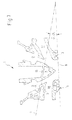
- FIGS. 7 to 9 show the first, in FIG. 3 illustrated embodiment of the cylinder head 1 in cross section along in FIG. 3 indicated section plane II-II. This section passes through an inlet or outlet channel 17, 18th
- FIG. 7 can be seen, divided in this sectional plane II-II of the cooling jacket core 3 in four subcool jacket cores 3, of which two are arranged on the right and two left of an imaginary longitudinal axis.
- the inlet channel 17 and the outlet channel 8 have a rather elongated shape in this sectional plane.
- the uppermost walls 15 of the cooling jacket core 3 lie in the virtual roof level 5.
- the angle ⁇ which defines the mounting position and is located between the cylinder head bottom 7 and the horizontal plane 6, is therefore 0 °.
- FIGS. 8 and 9 show the first embodiment of the cylinder head 1 in the in FIG. 7 shown section plane II-II in two different mounting positions.
- This section III-III is placed so that it passes through a coring point 8 centered between two cylinders.
- the Entkernungsstelle 8 must be provided for casting technical reasons in order to remove the sand core from the cylinder head blank after the casting process can. This is a point 8 of the cooling jacket core 3, to which only little influence can be taken with regard to optimized ventilation.
- the cooling jacket core 3 or the outer wall 15 facing the roof plane 5 has a local maximum 10, which is caused by the lug 21, so that the walls of the cooling jacket core facing the roof plane 5 are not continuous. continuously rise in the direction of the vent strip 4.
- FIG. 10 illustrated embodiment of a four-cylinder in-line engine, it has proved to be advantageous to arrange the Entkernungsstellen 8 in the manner described, which is why this arrangement was not waived.
- Entkernungsstelle 8 is to be regarded only as an example of a critical point of the cylinder head at the local casting for technical reasons, maxima can not be avoided, so given after the casting process a way to remove the sand core from the cylinder head blank is.
- a sensor bore which is provided for receiving a temperature sensor and leads to the formation of local maxima of the coolant jacket in the region of the bore.
Landscapes
- Engineering & Computer Science (AREA)
- Chemical & Material Sciences (AREA)
- Combustion & Propulsion (AREA)
- Mechanical Engineering (AREA)
- General Engineering & Computer Science (AREA)
- Cylinder Crankcases Of Internal Combustion Engines (AREA)
Claims (7)
- Culasse (1) d'un moteur à combustion interne comprenant des canaux d'entrée (17) et des canaux de sortie (18), les canaux d'entrée (17) et les canaux de sortie (18) sortant de la culasse (1) par différents côtés, et comprenant une chemise de réfrigérant (2) comprenant un noyau de chemise de refroidissement d'une seule pièce (3) et au moins une barre de désaérage (4),
un plan de toit (5) virtuel posé par le dessus sur le noyau de chemise de refroidissement (3) s'étendant horizontalement ou montant dans la direction de l'au moins une barre de désaérage (4), dans la position de montage de la culasse (1) dans laquelle le fond de culasse (7) est incliné d'un angle β par rapport à un plan horizontal (6), de sorte que le plan de toit (5) forme avec le plan horizontal (6), dans la position de montage, un angle α ≥ 0°, caractérisée en ce qu'il y a deux canaux d'entrée (17) et deux canaux de sortie (18) par cylindre. - Culasse (1) selon la revendication 1,
caractérisée en ce que
l'angle α est < 45°. - Culasse (1) selon la revendication 1 ou 2,
caractérisée en ce que
l'angle α est < 10°. - Culasse (1) selon l'une quelconque des revendications précédentes,
caractérisée en ce que
dans la position de montage de la culasse (1) - sans compter les exceptions inévitables du point de vue de la technique de coulée, comme les points de débourrage (8) - des parois extérieures (15) du noyau de chemise de refroidissement (3), qui sont tournées vers le plan de toit (5), montent constamment dans la direction de l'au moins une barre de désaérage (4), de sorte qu'elles ne présentent pas de maxima locaux (10). - Culasse (1) selon l'une quelconque des revendications précédentes,
caractérisée en ce que
le plan de toit (5) forme avec le fond de culasse (7) un angle δ, avec 9° < δ < 15°, et |δ| > |β|. - Culasse (1) selon la revendication 5,
caractérisée en ce que
le plan de toit (5) forme avec le fond de culasse (7) un angle δ, avec 11° < δ < 13°, et |δ| > 151. - Culasse (1) selon l'une quelconque des revendications précédentes,
caractérisée en ce que
le moteur à combustion interne est un moteur en ligne, de préférence un moteur en ligne à quatre cylindres.
Priority Applications (2)
| Application Number | Priority Date | Filing Date | Title |
|---|---|---|---|
| EP20030104538 EP1538327B1 (fr) | 2003-12-04 | 2003-12-04 | Culasse avec chemise de refroidissement qui contient un noyau de coulée et conduit d'aération |
| DE50312816T DE50312816D1 (de) | 2003-12-04 | 2003-12-04 | Zylinderkopf mit einem Kühlmittelmantel, der einen Kühlmantelkern und eine Entlüftungsleiste umfasst |
Applications Claiming Priority (1)
| Application Number | Priority Date | Filing Date | Title |
|---|---|---|---|
| EP20030104538 EP1538327B1 (fr) | 2003-12-04 | 2003-12-04 | Culasse avec chemise de refroidissement qui contient un noyau de coulée et conduit d'aération |
Publications (2)
| Publication Number | Publication Date |
|---|---|
| EP1538327A1 EP1538327A1 (fr) | 2005-06-08 |
| EP1538327B1 true EP1538327B1 (fr) | 2010-06-16 |
Family
ID=34443067
Family Applications (1)
| Application Number | Title | Priority Date | Filing Date |
|---|---|---|---|
| EP20030104538 Expired - Lifetime EP1538327B1 (fr) | 2003-12-04 | 2003-12-04 | Culasse avec chemise de refroidissement qui contient un noyau de coulée et conduit d'aération |
Country Status (2)
| Country | Link |
|---|---|
| EP (1) | EP1538327B1 (fr) |
| DE (1) | DE50312816D1 (fr) |
Families Citing this family (3)
| Publication number | Priority date | Publication date | Assignee | Title |
|---|---|---|---|---|
| DE102007027719B4 (de) * | 2007-06-15 | 2015-05-13 | Audi Ag | Brennkraftmaschine mit einem Heizungskreislauf und einem Kühlkreislauf |
| FR2960916A1 (fr) * | 2010-06-03 | 2011-12-09 | Peugeot Citroen Automobiles Sa | Culasse, noyau pour la fabrication de cette culasse, procede de fabrication de cette culasse, et vehicule |
| FR3058473B1 (fr) * | 2016-11-04 | 2019-07-12 | Peugeot Citroen Automobiles Sa | Culasse de moteur thermique |
Family Cites Families (6)
| Publication number | Priority date | Publication date | Assignee | Title |
|---|---|---|---|---|
| FR1006447A (fr) * | 1948-01-16 | 1952-04-23 | Kloeckner Humboldt Deutz Ag | Moteur à combustion interne |
| JPS6017255A (ja) * | 1983-07-11 | 1985-01-29 | Nissan Motor Co Ltd | 沸騰冷却方式エンジンのシリンダヘツド |
| JPS6060242A (ja) * | 1983-09-08 | 1985-04-06 | Nissan Motor Co Ltd | 沸騰冷却式エンジン |
| DE4036810C1 (fr) * | 1990-11-19 | 1991-12-05 | Dr.Ing.H.C. F. Porsche Ag, 7000 Stuttgart, De | |
| DK0782665T3 (da) * | 1994-09-19 | 1999-05-10 | Motoren Werke Mannheim Ag | Forbrændingsmotor |
| JP2000073857A (ja) * | 1998-08-31 | 2000-03-07 | Honda Motor Co Ltd | 内燃機関におけるシリンダヘッド構造 |
-
2003
- 2003-12-04 EP EP20030104538 patent/EP1538327B1/fr not_active Expired - Lifetime
- 2003-12-04 DE DE50312816T patent/DE50312816D1/de not_active Expired - Lifetime
Also Published As
| Publication number | Publication date |
|---|---|
| DE50312816D1 (de) | 2010-07-29 |
| EP1538327A1 (fr) | 2005-06-08 |
Similar Documents
| Publication | Publication Date | Title |
|---|---|---|
| DE112009000837B4 (de) | Wärmetauscher | |
| DE602004006659T2 (de) | Vorrichtung zur Regelung von Kurbelwellengas | |
| EP2322785B1 (fr) | Système de refroidissement | |
| EP2003320B1 (fr) | Culasse de moteur à combustion interne | |
| DE60034962T2 (de) | Integriertes abgasrückführungsventil | |
| DE2950905A1 (de) | Kuehleinrichtung sowie zylinderkopf fuer verbrennungsmotor | |
| DE69918194T2 (de) | Zylinderblockaufbau | |
| DE102010038055A1 (de) | Brennkraftmaschine mit Flüssigkeitskühlung | |
| DE102004052788A1 (de) | Zylinderkopfdichtung zum Einsatz in einer Brennkraftmaschine und damit ausgerüstete Brennkraftmaschine | |
| EP1778964B1 (fr) | Pistons en metal leger ayant des tubes echangeurs de chaleur | |
| EP1398589A2 (fr) | Radiateur pour liquide de refroidissement | |
| EP3339617A1 (fr) | Boîtier de cylindre, procédé de fabrication d'un boîtier de cylindre et noyau de coulée | |
| DE60224147T2 (de) | Wasserkühlvorrichtung für eine vertikale Mehrzylinderbrennkraftmaschine | |
| DE69100092T2 (de) | Zylindergehaeuse fuer eine maschine mit dampfabfuhr und oelrueckfuehrleitungen. | |
| DE3424470C2 (de) | Verbrennungskraftmaschine | |
| DE112004001923B4 (de) | Hochdruck-Wärmebehandlungsofen | |
| DE68903686T2 (de) | Kuehlungsanlage einer brennkraftmaschine. | |
| DE102004019853B4 (de) | Zylinderkopfstruktur | |
| DE102018124888A1 (de) | Kühlmantel für Zylinderkopf | |
| EP1538327A1 (fr) | Culasse avec chemise de refroidissement qui contient un noyau de coulée et conduit d'aération | |
| DE102020003394A1 (de) | Gekühlter Zylinderkopf | |
| DE19509002C2 (de) | Thermostatanbaupositionsstruktur | |
| DE2818436A1 (de) | Zylinderkopf einer brennkraftmaschine | |
| DE3702272A1 (de) | Tauchkolben fuer verbrennungsmotoren mit einem von kuehloel durchstroemten hohlraum | |
| DE2622290A1 (de) | Abgaskuehlvorrichtung fuer eine verbrennungsmaschine |
Legal Events
| Date | Code | Title | Description |
|---|---|---|---|
| PUAI | Public reference made under article 153(3) epc to a published international application that has entered the european phase |
Free format text: ORIGINAL CODE: 0009012 |
|
| AK | Designated contracting states |
Kind code of ref document: A1 Designated state(s): AT BE BG CH CY CZ DE DK EE ES FI FR GB GR HU IE IT LI LU MC NL PT RO SE SI SK TR |
|
| AX | Request for extension of the european patent |
Extension state: AL LT LV MK |
|
| 17P | Request for examination filed |
Effective date: 20051208 |
|
| AKX | Designation fees paid |
Designated state(s): DE FR GB |
|
| 17Q | First examination report despatched |
Effective date: 20070403 |
|
| GRAP | Despatch of communication of intention to grant a patent |
Free format text: ORIGINAL CODE: EPIDOSNIGR1 |
|
| GRAS | Grant fee paid |
Free format text: ORIGINAL CODE: EPIDOSNIGR3 |
|
| GRAA | (expected) grant |
Free format text: ORIGINAL CODE: 0009210 |
|
| AK | Designated contracting states |
Kind code of ref document: B1 Designated state(s): DE FR GB |
|
| REF | Corresponds to: |
Ref document number: 50312816 Country of ref document: DE Date of ref document: 20100729 Kind code of ref document: P |
|
| PLBI | Opposition filed |
Free format text: ORIGINAL CODE: 0009260 |
|
| 26 | Opposition filed |
Opponent name: AVL LIST GMBH Effective date: 20110316 |
|
| PLAX | Notice of opposition and request to file observation + time limit sent |
Free format text: ORIGINAL CODE: EPIDOSNOBS2 |
|
| REG | Reference to a national code |
Ref country code: DE Ref legal event code: R026 Ref document number: 50312816 Country of ref document: DE Effective date: 20110316 |
|
| PLBB | Reply of patent proprietor to notice(s) of opposition received |
Free format text: ORIGINAL CODE: EPIDOSNOBS3 |
|
| PLCK | Communication despatched that opposition was rejected |
Free format text: ORIGINAL CODE: EPIDOSNREJ1 |
|
| APBM | Appeal reference recorded |
Free format text: ORIGINAL CODE: EPIDOSNREFNO |
|
| APBP | Date of receipt of notice of appeal recorded |
Free format text: ORIGINAL CODE: EPIDOSNNOA2O |
|
| APAH | Appeal reference modified |
Free format text: ORIGINAL CODE: EPIDOSCREFNO |
|
| REG | Reference to a national code |
Ref country code: FR Ref legal event code: PLFP Year of fee payment: 13 |
|
| REG | Reference to a national code |
Ref country code: FR Ref legal event code: PLFP Year of fee payment: 14 |
|
| REG | Reference to a national code |
Ref country code: DE Ref legal event code: R100 Ref document number: 50312816 Country of ref document: DE |
|
| APBU | Appeal procedure closed |
Free format text: ORIGINAL CODE: EPIDOSNNOA9O |
|
| PLBN | Opposition rejected |
Free format text: ORIGINAL CODE: 0009273 |
|
| STAA | Information on the status of an ep patent application or granted ep patent |
Free format text: STATUS: OPPOSITION REJECTED |
|
| 27O | Opposition rejected |
Effective date: 20170125 |
|
| REG | Reference to a national code |
Ref country code: FR Ref legal event code: PLFP Year of fee payment: 15 |
|
| PGFP | Annual fee paid to national office [announced via postgrant information from national office to epo] |
Ref country code: FR Payment date: 20191122 Year of fee payment: 17 |
|
| PGFP | Annual fee paid to national office [announced via postgrant information from national office to epo] |
Ref country code: GB Payment date: 20191126 Year of fee payment: 17 |
|
| GBPC | Gb: european patent ceased through non-payment of renewal fee |
Effective date: 20201204 |
|
| PG25 | Lapsed in a contracting state [announced via postgrant information from national office to epo] |
Ref country code: FR Free format text: LAPSE BECAUSE OF NON-PAYMENT OF DUE FEES Effective date: 20201231 |
|
| PG25 | Lapsed in a contracting state [announced via postgrant information from national office to epo] |
Ref country code: GB Free format text: LAPSE BECAUSE OF NON-PAYMENT OF DUE FEES Effective date: 20201204 |
|
| PGFP | Annual fee paid to national office [announced via postgrant information from national office to epo] |
Ref country code: DE Payment date: 20220615 Year of fee payment: 20 |
|
| P01 | Opt-out of the competence of the unified patent court (upc) registered |
Effective date: 20230620 |
|
| REG | Reference to a national code |
Ref country code: DE Ref legal event code: R071 Ref document number: 50312816 Country of ref document: DE |