EP1538294A1 - Actionneur électromécanique à encombrement réduit pour grand angle d'ouverture - Google Patents
Actionneur électromécanique à encombrement réduit pour grand angle d'ouverture Download PDFInfo
- Publication number
- EP1538294A1 EP1538294A1 EP03027741A EP03027741A EP1538294A1 EP 1538294 A1 EP1538294 A1 EP 1538294A1 EP 03027741 A EP03027741 A EP 03027741A EP 03027741 A EP03027741 A EP 03027741A EP 1538294 A1 EP1538294 A1 EP 1538294A1
- Authority
- EP
- European Patent Office
- Prior art keywords
- housing
- stroke
- wing
- locking
- drive
- Prior art date
- Legal status (The legal status is an assumption and is not a legal conclusion. Google has not performed a legal analysis and makes no representation as to the accuracy of the status listed.)
- Withdrawn
Links
Images


Classifications
-
- E—FIXED CONSTRUCTIONS
- E05—LOCKS; KEYS; WINDOW OR DOOR FITTINGS; SAFES
- E05F—DEVICES FOR MOVING WINGS INTO OPEN OR CLOSED POSITION; CHECKS FOR WINGS; WING FITTINGS NOT OTHERWISE PROVIDED FOR, CONCERNED WITH THE FUNCTIONING OF THE WING
- E05F15/00—Power-operated mechanisms for wings
- E05F15/60—Power-operated mechanisms for wings using electrical actuators
- E05F15/603—Power-operated mechanisms for wings using electrical actuators using rotary electromotors
- E05F15/611—Power-operated mechanisms for wings using electrical actuators using rotary electromotors for swinging wings
- E05F15/63—Power-operated mechanisms for wings using electrical actuators using rotary electromotors for swinging wings operated by swinging arms
-
- E—FIXED CONSTRUCTIONS
- E05—LOCKS; KEYS; WINDOW OR DOOR FITTINGS; SAFES
- E05F—DEVICES FOR MOVING WINGS INTO OPEN OR CLOSED POSITION; CHECKS FOR WINGS; WING FITTINGS NOT OTHERWISE PROVIDED FOR, CONCERNED WITH THE FUNCTIONING OF THE WING
- E05F15/00—Power-operated mechanisms for wings
- E05F15/60—Power-operated mechanisms for wings using electrical actuators
- E05F15/603—Power-operated mechanisms for wings using electrical actuators using rotary electromotors
- E05F15/611—Power-operated mechanisms for wings using electrical actuators using rotary electromotors for swinging wings
- E05F15/616—Power-operated mechanisms for wings using electrical actuators using rotary electromotors for swinging wings operated by push-pull mechanisms
- E05F15/622—Power-operated mechanisms for wings using electrical actuators using rotary electromotors for swinging wings operated by push-pull mechanisms using screw-and-nut mechanisms
-
- E—FIXED CONSTRUCTIONS
- E05—LOCKS; KEYS; WINDOW OR DOOR FITTINGS; SAFES
- E05Y—INDEXING SCHEME ASSOCIATED WITH SUBCLASSES E05D AND E05F, RELATING TO CONSTRUCTION ELEMENTS, ELECTRIC CONTROL, POWER SUPPLY, POWER SIGNAL OR TRANSMISSION, USER INTERFACES, MOUNTING OR COUPLING, DETAILS, ACCESSORIES, AUXILIARY OPERATIONS NOT OTHERWISE PROVIDED FOR, APPLICATION THEREOF
- E05Y2201/00—Constructional elements; Accessories therefor
- E05Y2201/10—Covers; Housings
- E05Y2201/11—Covers
-
- E—FIXED CONSTRUCTIONS
- E05—LOCKS; KEYS; WINDOW OR DOOR FITTINGS; SAFES
- E05Y—INDEXING SCHEME ASSOCIATED WITH SUBCLASSES E05D AND E05F, RELATING TO CONSTRUCTION ELEMENTS, ELECTRIC CONTROL, POWER SUPPLY, POWER SIGNAL OR TRANSMISSION, USER INTERFACES, MOUNTING OR COUPLING, DETAILS, ACCESSORIES, AUXILIARY OPERATIONS NOT OTHERWISE PROVIDED FOR, APPLICATION THEREOF
- E05Y2600/00—Mounting or coupling arrangements for elements provided for in this subclass
- E05Y2600/40—Mounting location; Visibility of the elements
-
- E—FIXED CONSTRUCTIONS
- E05—LOCKS; KEYS; WINDOW OR DOOR FITTINGS; SAFES
- E05Y—INDEXING SCHEME ASSOCIATED WITH SUBCLASSES E05D AND E05F, RELATING TO CONSTRUCTION ELEMENTS, ELECTRIC CONTROL, POWER SUPPLY, POWER SIGNAL OR TRANSMISSION, USER INTERFACES, MOUNTING OR COUPLING, DETAILS, ACCESSORIES, AUXILIARY OPERATIONS NOT OTHERWISE PROVIDED FOR, APPLICATION THEREOF
- E05Y2900/00—Application of doors, windows, wings or fittings thereof
- E05Y2900/10—Application of doors, windows, wings or fittings thereof for buildings or parts thereof
- E05Y2900/13—Type of wing
- E05Y2900/148—Windows
Definitions
- the invention relates to an electric motor drive with integrated lock for a wing of windows or doors.
- the drive is suitable for all types of Wings, such as tilting windows, folding windows, rotating windows, swing windows or turning windows and for corresponding wings of doors as well.
- the opening angle should reach at least about 60 °, as this maximum section (area) of the opening is achieved for ventilation. Smaller opening angles should be steplessly controlled.
- Electromotive drive should still be particularly suitable for tight Space on the fixed frame, as for example in mullion and transom constructions to occur in facades.
- the solutions are based on the concept, the two different functions, namely the unlocking (and / or locking) on the one hand and the opening (and / or Close) of the wing on the other hand, a respective different lifting movement assigned.
- the two strokes correspond to two in a common housing movable drive parts A, B, which are independent of each other once and for others but also together (coupled) are movable.
- Both drive parts are - when they are coupled - by the same motor Drive powered.
- the other movable part B in the housing engages with an engagement element (rod, Plate or tab) by the wing flap in the interior of the rebate.
- the Engagement member is - in the assembled state - in engagement with a central closure (Locking linkage), so that the movement of this movable part B for Unlocking and locking the wing is used (claim 22, 23).
- the threaded rod (spindle) of the drive in Set longitudinally of the housing, so that with the spindle nut on the Thread of the non-rotating rod, the engine as a whole moved in the longitudinal direction.
- the drive link is located next to and parallel to a median plane (longitudinal plane) through the housing so that for supporting the other end of the handlebar at the Frame only a very narrow area is needed for mounting.
- the two strokes can simultaneously from the closed position of the wing start (claim 3), but are different lengths. These are “other strokes”, here partially overlapping. But it is just as possible, the opening stroke only after completion to use the Entriegelungshubes (claim 4). Again, there are others Strokes.
- the spindle (threaded rod) is rotatable and the Motor of the drive unit is connected to the housing, in particular at one end immovably connected.
- a portion of the entire transmission drive unit remains movable and is called “longitudinal sliding section" of the spindle through her Rotational movement moves in the longitudinal direction.
- the rotary motion transfers to one the sliding portion firmly coupled spindle nut. Due to the arrangement of the engine of Drive unit at one end of the housing is created movement space of the stroke or movement of the movable section (as sliding section) can be used after it has been disconnected from the guide section.
- the spring device (claim 13) holds the waiting position of the guide element until a re-engagement took place.
- the working or actuating link (claim 10) can for the combined pivot opening and the longitudinal release perform a combined movement, out of one Parallel shift and a tilt (claim 21).
- the change between the both movements essentially takes place simultaneously with the coupling or Disconnect the two moving parts in the housing instead (above as Part A and Part B) designated), cf. Claim 24.
- the driving force for the operation, the work handlebar refers to the movement of a the two parts (claim 5).
- the position of the coupling (claim 6) between the two located in the housing Divide A, B is dependent on the longitudinal position of the two coupling parts, the one rigid coupling hook and the other elastically resilient latching element.
- the Position of the release of this clutch is at a breakthrough of a control plate of the Housing, which breakthrough a pivotal movement of the under bias allowed standing locking element.
- a control cam on the control cam part (claim 10, 11 and 14) has a straight Section and a curved section, wherein the straight section closer to the Longitudinal guide is located.
- the two sections merge and it takes hold a control pin which, relative to the slider located on the stop the Pivoting movement of the working arm for actuating the sash controls and leads (Claim 25).
- Another engaging piece, at a greater distance from the said pin on the working handlebar cooperates with a ramp to a Pressing force (the pre-tightening) of the wing in the end position when closing reach (claim 12).
- a spacer between the bottom of the housing and the mounting location on Rollover of the wing ensures a sufficient distance of the guide pin of the wing Working link and the support point of the handlebar in the slide (claim 16), also in the closed position of the wing.
- the space passing through the spacer element To achieve a desired torque is provided for the Housing a switching power supply, a receiver of a remote control or the like. be exploited.
- the cam part After the cam part is arranged on the fixed frame, is its narrow Training for the required space of advantage. It has no extra motor elements or other handlebars, only one main link as Häoder Operating handle, which the combined movement of longitudinal displacement and rotation performs (claim 15, 26 and 27).
- the cam part In a design specification can the cam part have a narrow width, which is narrower than the comparable width of the housing in which the electric motor drive located is.
- the control cam part can also be made substantially narrower, in particular narrower than half the width of the housing (claim 17).
- the length of the engaging member is dimensioned so that the coupling pin for Locking linkage is achieved (claim 18), wherein the out of the housing Outstanding section will be so long that it passes through the spacer (Claim 16), by the rollover of the wing and a piece in the rebate can reach into it.
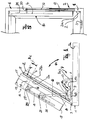
- a wing 2 is pivotally mounted on the fixed or frame 1 with a hinge 3 hinged. It can be a tilt or a folding wing or a Drehmut (short: "wings") act. On the sash inside is under Interposition of a spacer 15, the housing 16 of the drive mounted, in which various drive elements are arranged.
- the spacer 15 is provided to pass through the opening and Closing movements of the drive to obtain correspondingly large torques.
- the opened wing 2 gives the view of a central lock 4 with a Locking pin 5 (or more), which in closing the wing in corresponding Lock plates 5a of the frame 1 engage.
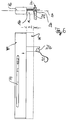
- FIG. 6 illustrates the engagement element 21 formed as a bar or plate, as it engages through the slot 2b in the flap 2 a of the wing 2.
- a longitudinal slot 19 is provided, through which a Pin 20 engages, on which one end of the drive link 10 is articulated.
- the other end of the arm 10 is hinged to a sliding member 9, which in a Guide 8 a mounted on the frame 1 articulation and control cam part 7 (as Support element) is provided.
- the guide 8 is open to one side and has in front the other end a stop 49.
- the cam part has at one upstanding flange 7a on a cam 11, in which a pin or a roller 12th of the handlebar 10 engages.
- a Voranzugsschräge 13 provided with the closing movement another Engaging piece, such as pin or roller 14 of the handlebar 10 cooperates to in End of the closing movement a mechanical pressure as Voranzug the wing to ensure with closing pressure force on the frame.
- a mechanical pressure as Voranzug the wing to ensure with closing pressure force on the frame.
- the housing 16 is closed at its ends by end plates 17 and 18.
- Figure 1 has through the slot 19 through a limited view of the im Housing arranged gear / drive 25.
- H1 the stroke used for locking and unlocking is Central closure 4 denotes.
- the swinging of the wing opposite the Frame when opening and closing indicates ⁇ .
- H2 is the way to open and Close with the angle ⁇ . Open / Close also refers to the Actuation of the drive itself.
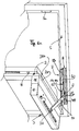
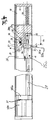
- Figures 2 and 3 show - with reference to Figure 1 - the respective upper portion of the housing 16, as can be seen on the end plate 17 and the pin 20 as a reference.
- the parts indicated at 25a, 25b and 25c belong to the transmission / drive 25.
- The are mainly the electric motor 25a, the intermediate gear 25b and the Spindle nut 25 c, which is arranged on the spindle 27.
- the spindle 27 at 28 with a locking piece in the housing 16 against rotation and Longitudinal movements secured and anchored. This means that along with the Spindle nut, the entire transmission / drive 25 together with a Sliding element 26 can move longitudinally as a unit in the housing.
- To gear / drive unit 25,26 includes a run in the housing slide 26, which is permanently assigned. This slider has the connecting pin 20, the through the housing slot 19 engages outwardly and with the handlebar 10 pivotally is coupled.
- a guide member 29 is arranged longitudinally movable.
- the Longitudinal movement of the guide element 29 is limited, for example by a Longitudinal slot 31, of the fixed point of the spindle-forming bolt 28th is penetrated.
- FIG 2 the position of the guide member 29 is shown, in which the wing is in the Closed position and is locked by the central lock 4.
- the Locking piece 28 is located at the one end of the guide slot 31 while it is located in Figure 3 at the opposite end of this slot.
- the position of Guide element 29 of Figure 3 is the position in which the central closure the Has released wings, i. the central lock is unlocked, caused by the Engagement part 21.
- the engagement part 21, with the pin 6 of the central closure. 4 cooperates, is provided on the guide member 29.
- the guide member 29 is under the bias of a spring 30, located on the End plate 17 of the housing 16 is supported. In the position of Figure 2, the spring curious, in the position of Figure 3, it is partially relaxed.
- the guide part 29 Thus, as shown in Figure 3, the necessary according to Figure 1 first stroke H1 (as distance), which can be unlocked (when opening) and locked (at Close) is provided. After unlocking, in position + H1, the spring 30 holds the Element 29 in position, for example, at the right end of the longitudinal slot 31st
- the sliding member 26, which is fixedly connected to the transmission / drive 25, has a rigid coupling member 35 which in the longitudinal direction of the housing on the Guide member 29 is aligned towards.
- the rigid coupling member faces both Longitudinal directions bevels 36a, 36b and forms part of a in Depending on the stroke automatically controlled clutch 34.
- the other part of this Clutch sits as a locking element 37 on the guide member 29 and is pivotable stored 38 and is under the bias of a spring 40th
- the stroke-dependent control of the clutch 34 uses a in the housing Placed flat piece 32 as a control aid that at a certain point of the Hubweges has an opening 33, in which a head piece 39 upon reaching a certain stroke can intervene.
- the head piece 39 is connected to the locking element 37 firmly connected and also pivotable about the bearing 38.
- the locking element 37 slides before touching the surfaces 29a / 25d on the slope 36b and comes into locking engagement with the rigid coupling member 35, wherein the Head 39 returns from the recess 33 and during the stroke -H1 (H1 in -z-direction) on the inside of the control plate 32 and thus the coupling locks against opening.
- the locking of the wing is thus effected by the electromechanical drive of Transmission / drive 25, which also biases the spring 30 until the initial state is reached again according to FIG.
- the same motor 25a opens and closes the wing unlocked sliding element 26.
- the two strokes H1 are indicated for unlocking and locking and H2 for the opening and closing of the wing.
- These two separate strokes H1, H2, ie the beginning of the stroke H2 at the end of the stroke H1, are an approach.
- a second approach is that the stroke H2 starts together with the stroke H1 at the point marked by a circle in FIG. 2, then the stroke H1 ends and the stroke H2 continues.
- the stroke responsible for the pivotal movement is then H2-H1, while the stroke responsible for unlocking and locking is H1 (longitudinally measured in the longitudinal direction of the housing 16).
- the motor was 25,26 as the engine-transmission unit with the longitudinally movable sliding portion 26 together to a moving unit summarized.
- a section of this movement unit is analogous in FIG independently, but continue on the spindle rod 27 is a functional part of the "Drive unit", which here consists of a longitudinally movable section and an in Longitudinally fixed section exists.
- Figure 6 illustrates the penetration of the Eingreifarms 21 with its receptacle 21a for the pin 6 of the locking linkage 4.
- the illustrated space of height ER below the housing is penetrated by the engagement arm 21, for which a gap 15b is provided.
- the remaining area of this (hollow) intermediate part 15 can be used for receiving electronic and electrical components, such as switching power supply or load shedding and / or receiver of a remote control or load shedding for the engine.
- the arm 21 engages through a gap 2b of the flap 2a of the wing 2, as shown in FIG Side view was shown.
- the Center plane 100 can be seen, parallel to the laterally displaced the protruding of the Engagement arm 21 takes place. He is not centrally located in the housing 16, but for a flat side shifted.
Landscapes
- Power-Operated Mechanisms For Wings (AREA)
Priority Applications (2)
| Application Number | Priority Date | Filing Date | Title |
|---|---|---|---|
| EP03027741A EP1538294A1 (fr) | 2003-12-02 | 2003-12-02 | Actionneur électromécanique à encombrement réduit pour grand angle d'ouverture |
| DE200410058208 DE102004058208A1 (de) | 1980-07-22 | 2004-12-02 | Elektromotorischer Antrieb mit einem großen Öffnungswinkel und schmaler Bauform |
Applications Claiming Priority (1)
| Application Number | Priority Date | Filing Date | Title |
|---|---|---|---|
| EP03027741A EP1538294A1 (fr) | 2003-12-02 | 2003-12-02 | Actionneur électromécanique à encombrement réduit pour grand angle d'ouverture |
Publications (1)
| Publication Number | Publication Date |
|---|---|
| EP1538294A1 true EP1538294A1 (fr) | 2005-06-08 |
Family
ID=34442947
Family Applications (1)
| Application Number | Title | Priority Date | Filing Date |
|---|---|---|---|
| EP03027741A Withdrawn EP1538294A1 (fr) | 1980-07-22 | 2003-12-02 | Actionneur électromécanique à encombrement réduit pour grand angle d'ouverture |
Country Status (1)
| Country | Link |
|---|---|
| EP (1) | EP1538294A1 (fr) |
Cited By (1)
| Publication number | Priority date | Publication date | Assignee | Title |
|---|---|---|---|---|
| EP2071111A3 (fr) * | 2007-12-14 | 2013-11-20 | Hartwig Grasl | Dispositif d'actionnement destiné à ouvrir et fermer un battant de fenêtre, de porte, de clapet d'aération ou analogue |
Citations (3)
| Publication number | Priority date | Publication date | Assignee | Title |
|---|---|---|---|---|
| CH560831A5 (en) * | 1973-12-18 | 1975-04-15 | Piatti Bruno | Window with reversible power actuator - has interacting members on fixed and moving frame for opening and closing and locking |
| DE19938253A1 (de) * | 1999-10-16 | 2001-02-15 | Winkhaus Fa August | Ausstellvorrichtung für einen an einem Rahmen schwenkbar angeordneten Kipp- oder Dreh-Kipp-Flügel und Dreh-Kipp-Flügel mit einer Ausstellvorrichtung |
| DE10148793A1 (de) * | 2000-10-12 | 2002-08-08 | Toni Huber | Einrichtung zum Verschliessen oder Freigeben einer Öffnung |
-
2003
- 2003-12-02 EP EP03027741A patent/EP1538294A1/fr not_active Withdrawn
Patent Citations (3)
| Publication number | Priority date | Publication date | Assignee | Title |
|---|---|---|---|---|
| CH560831A5 (en) * | 1973-12-18 | 1975-04-15 | Piatti Bruno | Window with reversible power actuator - has interacting members on fixed and moving frame for opening and closing and locking |
| DE19938253A1 (de) * | 1999-10-16 | 2001-02-15 | Winkhaus Fa August | Ausstellvorrichtung für einen an einem Rahmen schwenkbar angeordneten Kipp- oder Dreh-Kipp-Flügel und Dreh-Kipp-Flügel mit einer Ausstellvorrichtung |
| DE10148793A1 (de) * | 2000-10-12 | 2002-08-08 | Toni Huber | Einrichtung zum Verschliessen oder Freigeben einer Öffnung |
Cited By (1)
| Publication number | Priority date | Publication date | Assignee | Title |
|---|---|---|---|---|
| EP2071111A3 (fr) * | 2007-12-14 | 2013-11-20 | Hartwig Grasl | Dispositif d'actionnement destiné à ouvrir et fermer un battant de fenêtre, de porte, de clapet d'aération ou analogue |
Similar Documents
| Publication | Publication Date | Title |
|---|---|---|
| EP2459824B1 (fr) | Dispositif de fermeture de porte | |
| EP1187963B1 (fr) | Dispositif de blocage et dispositif d'entrainement de porte pourvu d'un tel dispositif de blocage et destine a une porte entrainee par un groupe moteur | |
| EP3401475B1 (fr) | Système d'armatures | |
| DE102009039322B3 (de) | Vorrichtung zum Verriegeln oder Entriegeln eines Schiebeflügels | |
| EP1022421B1 (fr) | Dispositif déflecteur pour panneau basculant ou oscillo-battant monté pivotant sur un cadre | |
| EP1516984A2 (fr) | Dispositif de déverrouillage de secours pour portes pivotantes-coulissantes, notamment pour un véhicule ferroviaire | |
| DE4321099A1 (de) | Belüftungseinrichtung für Fenster oder Türen | |
| EP2146032B1 (fr) | Dispositif destiné à ouvrir et/ou fermer ainsi qu'à verrouiller un état fermé d'un dispositif de fermeture destiné à fermer une ouverture de salle ainsi que dispositif de fermeture doté d'un tel dispositif | |
| EP3921499B1 (fr) | Dispositif d'entraînement pivotant d'un battant | |
| DE19951289C2 (de) | Sperrvorrichtung und damit versehene Torantriebsvorrichtung für ein mittels eines Motorantriebsaggregats antreibbares Tor | |
| DE102005002180A1 (de) | Vertikal-Steuervorrichtung für einen Hebe-Schiebeflügel | |
| DE9007232U1 (de) | Treibstangenverschluß | |
| DE102007025723B3 (de) | Kupplungseinheit für ein Garagentor, insbesondere Kipp-, Schwenk- oder Sektionaltor | |
| EP0610948A1 (fr) | Appareil pour l'ouverture et la fermeture mécanique de fenêtres avec ferrure cachée | |
| EP1083281B1 (fr) | Dispositif de verrouillage pour porte, fenêtre ou similaires | |
| DE19717351A1 (de) | Klappschwingfenster | |
| EP1514985A2 (fr) | Dispositif de verrouillage pour portes de véhicules, notamment portes pivotantes-coulissantes pour un véhicule ferroviaire | |
| EP2143864B1 (fr) | Fenêtre, porte ou analogue, ainsi que compas avec levier à bras de projection pour une telle fenêtre, une telle porte ou analogue | |
| DE102020103758A1 (de) | Funktionseinheit | |
| EP1170445A2 (fr) | Dispositif déflecteur pour panneau basculant ou oscillo-battant monté pivotant sur un cadre | |
| DE10343359A1 (de) | Ver- und Entriegelungsvorrichtung für zweiflügelige Fahrzeugtüren, insbesondere Schwenkschiebetüren für Schienenfahrzeuge | |
| EP1288418B1 (fr) | Ferrure pour une fenêtre basculante ou oscillo-battante | |
| DE19944050A1 (de) | Verriegelungsvorrichtung | |
| DE102004058208A1 (de) | Elektromotorischer Antrieb mit einem großen Öffnungswinkel und schmaler Bauform | |
| EP3211165A1 (fr) | Dispositif d'ouverture d'un vantail oscillo-battant d'une fenêtre ou d'une porte destiné au basculement motorisé et à la rotation et au basculement manuels |
Legal Events
| Date | Code | Title | Description |
|---|---|---|---|
| PUAI | Public reference made under article 153(3) epc to a published international application that has entered the european phase |
Free format text: ORIGINAL CODE: 0009012 |
|
| 17P | Request for examination filed |
Effective date: 20041122 |
|
| AK | Designated contracting states |
Kind code of ref document: A1 Designated state(s): AT BE BG CH CY CZ DE DK EE ES FI FR GB GR HU IE IT LI LU MC NL PT RO SE SI SK TR |
|
| AX | Request for extension of the european patent |
Extension state: AL LT LV MK |
|
| AKX | Designation fees paid |
Designated state(s): AT BE BG CH CY CZ DE DK EE ES FI FR GB GR HU IE IT LI LU MC NL PT RO SE SI SK TR |
|
| RAP1 | Party data changed (applicant data changed or rights of an application transferred) |
Owner name: HAUTAU GMBH |
|
| RAP1 | Party data changed (applicant data changed or rights of an application transferred) |
Owner name: HAUTAU GMBH |
|
| STAA | Information on the status of an ep patent application or granted ep patent |
Free format text: STATUS: THE APPLICATION IS DEEMED TO BE WITHDRAWN |
|
| 18D | Application deemed to be withdrawn |
Effective date: 20130702 |