EP1536996B1 - Unite d'entrainement presentant un ralentisseur - Google Patents
Unite d'entrainement presentant un ralentisseur Download PDFInfo
- Publication number
- EP1536996B1 EP1536996B1 EP03750547A EP03750547A EP1536996B1 EP 1536996 B1 EP1536996 B1 EP 1536996B1 EP 03750547 A EP03750547 A EP 03750547A EP 03750547 A EP03750547 A EP 03750547A EP 1536996 B1 EP1536996 B1 EP 1536996B1
- Authority
- EP
- European Patent Office
- Prior art keywords
- retarder
- braking operation
- pressure
- vehicle cooling
- drive unit
- Prior art date
- Legal status (The legal status is an assumption and is not a legal conclusion. Google has not performed a legal analysis and makes no representation as to the accuracy of the status listed.)
- Expired - Lifetime
Links
- 238000001816 cooling Methods 0.000 claims abstract description 31
- 239000002826 coolant Substances 0.000 claims description 34
- 238000013016 damping Methods 0.000 claims description 21
- 230000007704 transition Effects 0.000 claims description 15
- 230000005540 biological transmission Effects 0.000 claims description 3
- 239000012530 fluid Substances 0.000 abstract description 14
- 230000006835 compression Effects 0.000 description 5
- 238000007906 compression Methods 0.000 description 5
- 238000011161 development Methods 0.000 description 3
- 230000018109 developmental process Effects 0.000 description 3
- XLYOFNOQVPJJNP-UHFFFAOYSA-N water Substances O XLYOFNOQVPJJNP-UHFFFAOYSA-N 0.000 description 3
- 230000001105 regulatory effect Effects 0.000 description 2
- 238000007789 sealing Methods 0.000 description 2
- 230000009286 beneficial effect Effects 0.000 description 1
- 230000003111 delayed effect Effects 0.000 description 1
- 230000001419 dependent effect Effects 0.000 description 1
- 238000007599 discharging Methods 0.000 description 1
- 238000000034 method Methods 0.000 description 1
- 238000005086 pumping Methods 0.000 description 1
- 239000003507 refrigerant Substances 0.000 description 1
- 230000000717 retained effect Effects 0.000 description 1
- 230000003068 static effect Effects 0.000 description 1
Images


Classifications
-
- F—MECHANICAL ENGINEERING; LIGHTING; HEATING; WEAPONS; BLASTING
- F01—MACHINES OR ENGINES IN GENERAL; ENGINE PLANTS IN GENERAL; STEAM ENGINES
- F01P—COOLING OF MACHINES OR ENGINES IN GENERAL; COOLING OF INTERNAL-COMBUSTION ENGINES
- F01P3/00—Liquid cooling
- F01P3/20—Cooling circuits not specific to a single part of engine or machine
-
- B—PERFORMING OPERATIONS; TRANSPORTING
- B60—VEHICLES IN GENERAL
- B60T—VEHICLE BRAKE CONTROL SYSTEMS OR PARTS THEREOF; BRAKE CONTROL SYSTEMS OR PARTS THEREOF, IN GENERAL; ARRANGEMENT OF BRAKING ELEMENTS ON VEHICLES IN GENERAL; PORTABLE DEVICES FOR PREVENTING UNWANTED MOVEMENT OF VEHICLES; VEHICLE MODIFICATIONS TO FACILITATE COOLING OF BRAKES
- B60T10/00—Control or regulation for continuous braking making use of fluid or powdered medium, e.g. for use when descending a long slope
- B60T10/02—Control or regulation for continuous braking making use of fluid or powdered medium, e.g. for use when descending a long slope with hydrodynamic brake
-
- F—MECHANICAL ENGINEERING; LIGHTING; HEATING; WEAPONS; BLASTING
- F16—ENGINEERING ELEMENTS AND UNITS; GENERAL MEASURES FOR PRODUCING AND MAINTAINING EFFECTIVE FUNCTIONING OF MACHINES OR INSTALLATIONS; THERMAL INSULATION IN GENERAL
- F16D—COUPLINGS FOR TRANSMITTING ROTATION; CLUTCHES; BRAKES
- F16D57/00—Liquid-resistance brakes; Brakes using the internal friction of fluids or fluid-like media, e.g. powders
- F16D57/04—Liquid-resistance brakes; Brakes using the internal friction of fluids or fluid-like media, e.g. powders with blades causing a directed flow, e.g. Föttinger type
Definitions
- the invention relates to a drive unit, in detail with the features the preamble of claim 1.
- These other units can also have a cooling circuit to to cool their working medium.
- the invention is based on the object, a drive unit with a filling and emptying retarders, especially water retarders, especially Secondary water retarder, showing in the pressure surges when switching from Braking operation for non-braking operation and vice versa does not occur or are at least largely reduced.
- a switched Damping cylinder connected to the coolant circuit, which at Switching from braking operation to non-braking operation a predetermined Working fluid quantity withdraws from the coolant circuit and when switching from non-braking operation to braking operation a predetermined Dispenses working fluid in the coolant circuit. It corresponds in particular the supplied working medium amount of the previously withdrawn Quantity of working medium.
- the damping cylinder is at the same time at two Sites in the coolant circuit connected so that it works automatically.
- Coolant circuit a bypass section with a switched bypass vent provided, which at the transition from braking operation to non-braking operation opens and an additional line section releases, which at least briefly absorbs a predetermined amount of working medium.
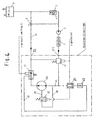
- FIG. 1 shows a secondary retarder 100 which is connected to the cooling medium of the Vehicle is operated.
- the retarder shown in Figure 1 is characterized a low power loss.
- the rotor blade wheel 11 is axially displaceable mounted on the rotor shaft 110, so that the rotor 11 in a working position close to the stator 12 or a rest position with a large distance to the stator 12 in Non-braking operation can be spent.
- the retarder is in Rest position shown.
- the displaceability of the rotor is on the WO Referenced 98/35171.
- the retarder shown in Figure 1 comprises a. Rotor 11, on one, z. In a gearbox mounted fast-running shaft 110, the so-called Retarderwelle, rotatably mounted and flying.
- the shaft 110 with the bearings 22nd and 23 is via a pinion 21 of the - not shown here - output shaft a gearbox driven.
- the rotor 11 is not on the shaft 110 by means of a shown helical gear longitudinally movable, so that the distance between Rotor and stator can be adjusted.
- the spring 18 adjusts the rotor 11 in Non-braking operation to the low-loss position shown here, i. between Rotor and stator 12 results in the largest possible gap.
- the retarder has one Retarder housing 130 with an interior 16, wherein the interior 16 with a cooling medium can be filled and then acts as a cooling jacket. Of the Space between the rotor 11 and stator 12 is referred to as working space 140 and is filled with working fluid.
- the hydrodynamic retarder is in the Integrated cooling circuit 120 of the motor vehicle. This is in the illustrated Embodiment of the retarder the working medium of the retarder simultaneously the cooling medium of the motor vehicle. To keep the no-load losses low, in non-braking operation, the retarder must be emptied, with emptying under also an emptying to a given residual working medium quantity understand which advantageously leads to a minimum power loss.
- a damping cylinder 30 is provided, which when switching from Braking operation for non-braking operation a predetermined amount of working fluid receives. Later, when switching from non-braking operation to braking operation becomes a pressure surge, which occurs because the retarder largely abruptly when filling a working medium amount from the rest Cooling circuit 120 deducted, thereby compensated that in the Damping cylinder 30 located working fluid amount the coolant circuit 120 is returned.
- the circuit of the damping cylinder 30, which has a piston 30.1 and a Compression spring 30.2 is regulated by the pressure in the line 38. Of the Pressure in the line 38 is in turn set via the valve 31. How one sees, the conduit 38 is flow-conducting with the side of the cylinder 30 connected, which is opposite to the compression spring side of the cylinder 30. Thus, the compression spring 30.2 pushes the piston against the pressure in the line 38th
- the hydrodynamic Retarder three different seals.
- Another seal 15 has in her Sealing function to fulfill two tasks.
- the Coolant via the line 19 constantly the interior 16 of the Retardergeophuses can flow as a cooling flow, absolutely towards the rotor and Stator sealed, d. H. the seal 15 assumes the non-braking operation Sealing function.
- the split ring seal 15.1 acts in braking mode as Non-contact labyrinth seal and the coolant flows through the Seal 15, which assumes no tightness in this case. This is ensures that the seal 14 in braking mode to the pressure level of closed cooling system is lowered.
- the interior 16 is designed so that it serves as a heat-dissipating cooling jacket of the Retarder works, in which the cooler medium flows via the line 19 and can drain via the line 20.
- FIGS 2 and 3 show alternative embodiments of the invention, which are characterized in that the supply and removal of the working medium by the damping cylinder 30 automatically and solely in dependence on Pressing in the coolant circuit takes place.
- the damping cylinder 30 is over the Line 42 working medium conductive to a point of high pressure behind the Retarder 100 and the emptying of the retarder 100 regulating control valve 17th connected and via a line 41 pressure-conducting to a point low Pressure in front of the retarder 100 behind the changeover valve 13.
- the switching valve 13 switches the Working medium flow such that the retarder 100 is no longer with Working medium is supplied via the line 43, but the entire Working medium via the bypass 66 at the line branch of the coolant circuit with the retarder 100 is guided past. Accordingly, the pressure in the sinks Line 43 and thus also in the pressure-connecting line 41 from.
- the piston 30.1 of the damping cylinder 30 is counter to the pressure force of the compression spring 30.2 and takes over the line 42 working medium from the Coolant circuit 120 on.
- the proportion of the working medium which is discharged from the retarder 100 during its emptying by the Damping cylinder 30 "caught", a corresponding pressure surge through the Emptying the retarder steamed.
- the changeover valve switches the working medium flow back into the line 43 in the direction of the retarder 100.
- the pressure in the conduit 43 and thus increases also in the pressure connection 41 to the damping cylinder 30 at.
- This Increasing pressure, together with the pressure force of the spring 30.2 presses the Piston 30.1 of the damping cylinder 30 opposite to the static pressure from the line 42 and thus pushes the located in the damping cylinder 30 Working fluid back into the coolant circuit 120. This will at least partially offset the pressure drop in the coolant circuit 120, which arises because the retarder 100 fills up.
- FIG. 3 essentially corresponds to FIG Embodiment according to the figure 2.
- the same components are the same Reference numerals as indicated in the figure 2.
- One difference lies in the Arrangement of the retarder circuit in the coolant circuit 120 of the vehicle. at switched retarder is namely in Figure 3, the branch of the Coolant circuit with the retarder 100 between the coolant pump 2 and involved in the engine 1.
- this circulation branch was in the Refrigerant circuit 120 integrated behind the engine 1.
- a switchable on passage shut-off valve 62 provided and a pressure relief line 64, with the Expansion tank 6 is connected.
- the pressure shut-off valve 62 is in the Pressure relief line 64 is arranged and is high when occurring Pressure peaks, for example an impulse when emptying the retarder, open. This additional measure can be used during retarder operation or when switching from braking operation to non-braking operation in Cooling circuit occurring pressure peaks are further reduced.
- the Pressure relief line 64 is connected directly to the expansion tank 6.
- FIG. 4 shows a further development of the invention.
- the illustrated Schematic shows actions that have been taken to transition from Braking operation for non-braking operation of the retarder 100 a pressure surge in System, especially in the line 51 to avoid largely. Further are Illustrated measures that may be implemented additionally or alternatively, a pressure surge or abrupt pressure drop at the transition from non-braking operation to braking operation.
- the former measures - Ausschaltrichvermeidung - are in essentially by the pressure-connected valve 62 with the connected Lines 64 and 65 embodied.
- the line 64 is with its the valve 62nd remote end disposed in a high pressure zone of the cooling circuit.
- a pressure of 11 bar prevail.
- Another advantageous connection option arises with the position between the illustrated check valve and the adjustable throttle in the control valve 17. There, for example, a pressure of 30 bar present.
- the line 64 is with its valve 62 facing away from the end in one Low pressure zone connected. There prevails advantageous pressure of maximum 2 bar.
- the connection can, for example, in the region of the inlet of the retarder 100 be provided, in particular on a filling channel in the retarder is trained.
- the control of the valve 62 is advantageously carried out with the same switching pulse, which also controls the valve 13. Both valves are in particular by a Pressure pulse switched (p-switched). At the transition from braking operation to Non-braking operation will switch the valve 62 from a closed position to a switched open position. As a result, a short-circuit flow over the retarder 100, that is, working medium, in this case the cooling medium of the Vehicle, flows from said high-pressure zone via the lines 64 and 65 in said low pressure zone. This will cause an expulsion of the entire Working medium, which in braking operation by the retarder or the connected piping was taken delayed in the line 51 fed, since the short-circuit flow a significant amount is initially retained in the area of the retarder 100. Thus, a Pressure surge in the line 51 avoided. The cooling circuit area between the Valve 13 and the valve 17 via the retarder 100 and at this connected lines is emptied evenly.
- a damping cylinder 30 which when switching from braking operation to Non-braking operation absorbs working medium and this in turn Switching from non-braking mode to braking mode.
- the working medium-carrying line 42 which opposite to the compression spring in the damping cylinder 30 is connected, with a high pressure area between the check valve and the adjustable throttle of the control valve 17 connected.
- a Throttle 43 is switched so that the transition from braking to Non-braking operation, the extracted working fluid quantity controlled from the Coolant circuit is sucked.
- this throttle 43 at Transition from non-braking operation to braking operation the working fluid quantity the damping cylinder 30 controlled fed into the coolant circuit 120.
- the control valve 17 is advantageous stated that in non-braking operation, the cooling circuit of the vehicle (starting with line 51) in non-braking operation completely opposite to the Line branch with the retarder 100 seals.
- the valve 13 which also advantageous in non-braking operation of the cooling circuit of the Vehicle (starting with the line branch, in which the engine 1 shown is) opposite the line region in which the retarder 100 is arranged, completely sealed.
- the valve 13 is also in non-braking operation such switched that the entire incoming coolant amount via the line 66th is directed into the line 51.
- valve 13 in the transition from non-braking operation to braking operation of the retarder in a Intermediate position, so that initially only part of the Cooling medium is passed via the line 67 to the retarder 100, while a another part continues to be routed via line 66 to line 51 and thus remains in the vehicle cooling circuit without having been passed through the retarder be.
- This water retainer unit 70 embodied according to the invention comprises in one embodiment, the retarder 100 and the means for compensating Pressure fluctuations when switching from braking operation to non-braking operation and vice versa.
- such means is the illustrated damping cylinder 30, in particular together with the throttle 43, the control valve 17 and the switching valve 13.
- the Wasserretarderü 70 further comprises the Pressure relief lines 64 and 65 with the interposed Druckabstellventil 62.
Landscapes
- Engineering & Computer Science (AREA)
- Mechanical Engineering (AREA)
- General Engineering & Computer Science (AREA)
- Fluid Mechanics (AREA)
- Physics & Mathematics (AREA)
- Transportation (AREA)
- Combustion & Propulsion (AREA)
- Chemical & Material Sciences (AREA)
- Transmission Of Braking Force In Braking Systems (AREA)
- Braking Arrangements (AREA)
- Lubrication Of Internal Combustion Engines (AREA)
- Portable Nailing Machines And Staplers (AREA)
- Graft Or Block Polymers (AREA)
Claims (9)
- Groupe moteur d'un véhicule avec un circuit de refroidissement de véhicule comprenant1.1 un ralentisseur hydrodynamique (100) avec une roue à pales (11) de rotor et une roue à pales (12) de stator,1.2 le ralentisseur hydrodynamique (100) étant disposé dans le circuit de refroidissement (120) du véhicule et le fluide de travail du ralentisseur étant le fluide caloporteur du véhicule,
caractérisé en ce que1.3 des moyens pour prélever une quantité prédéterminée de fluide de travail du circuit de refroidissement (120) du véhicule lors du passage du mode freinage au mode non-freinage de sorte que la quantité de fluide de travail circulant dans le circuit de refroidissement (120) du véhicule est diminuée de cette fraction prélevée et pour fournir au circuit de refroidissement (120) du véhicule une quantité prédéterminée de fluide de travail lors du passage du mode non-freinage au mode freinage de sorte que la quantité de fluide de travail circulant dans le circuit de refroidissement (120) du véhicule est augmentée de cette fraction rajoutée sont prévus sur le circuit de refroidissement (120) du véhicule. - Groupe moteur selon la revendication 1, caractérisé en ce qu'un cylindre amortisseur (30) commutable faisant office de moyen pour prélever et pour fournir une quantité prédéterminée de fluide de travail est branché sur le circuit de refroidissement (120) du véhicule de telle sorte qu'il prélève du circuit de refroidissement (120) du véhicule une quantité prédéterminée de fluide de travail lors du passage du mode freinage au mode non-freinage et qu'il fournit au circuit de refroidissement (120) du véhicule une quantité prédéterminée de fluide de travail lors du passage du mode non-freinage au mode freinage, la commutation étant commandée ou automatisée.
- Groupe moteur selon la revendication 2, caractérisé en ce que le cylindre amortisseur (30) comprend un piston (30.1) dont un côté est branché sur le circuit de refroidissement (120) du véhicule en amont de l'enceinte de travail (140) du ralentisseur (100) de façon à conduire la pression et est en outre soumis à une pression par un ressort de compression (30.2) dans le cylindre amortisseur (30) et dont l'autre côté est branché sur le circuit de refroidissement (120) du véhicule en aval de l'enceinte de travail (140) du ralentisseur (100) par l'intermédiaire d'une conduite (42).
- Groupe moteur selon l'une quelconque des revendications 1 à 3, caractérisé en ce qu'une conduite de décharge de pression (64, 65) avec une vanne d'arrêt (62) est branchée sur le circuit de refroidissement (120) du véhicule et/ou sur le ralentisseur (100), la vanne d'arrêt (62) installée dans la conduite de décharge de pression (64, 65) étant commandée de manière à s'ouvrir lors du passage du ralentisseur du mode freinage au mode non-freinage.
- Groupe moteur selon la revendication 4, caractérisé en ce que, à une extrémité, la conduite de décharge de pression (64, 65) est branchée en mode freinage en amont du ralentisseur (100) dans le sens d'écoulement à un endroit de basse pression et à son autre extrémité sur le ralentisseur (100) ou derrière le ralentisseur (100) à un endroit de pression élevée, la pression à l'endroit de basse pression ne dépassant notamment pas les 2 bar et la pression à l'endroit de pression élevée étant comprise entre 11 bar et 30 bar.
- Groupe moteur selon l'une quelconque des revendications 1 à 5, caractérisé en ce que le groupe moteur comporte un moteur (1) et un engrenage et que le ralentisseur (100) est un ralentisseur secondaire qui est disposé en aval de l'engrenage dans le sens des efforts exercés.
- Groupe moteur selon l'une quelconque des revendications 1 à 6, caractérisé en ce que les moyens destinés à prélever et à fournir une quantité prédéterminée de fluide de travail comprennent un cylindre amortisseur (30) comportant un piston (30.1) qui est branché par l'intermédiaire d'une conduite (42) d'un côté à un endroit de pression élevée sur le circuit de refroidissement (120) du véhicule en aval du ralentisseur (100) dans le sens d'écoulement de façon à conduire la pression et est branché sur son côté opposé par l'intermédiaire d'une conduite (41) à un endroit de pression basse sur le circuit de refroidissement (120) du véhicule en amont du ralentisseur (100).
- Groupe moteur selon la revendication 7, caractérisé en ce que la conduite (42) est branchée à son extrémité opposée au cylindre amortisseur (30) sur une valve de réglage (17) et que le groupe moteur comporte par ailleurs, en aval du raccord (71) pour alimenter le circuit en fluide caloporteur et en amont du ralentisseur (100) dans le sens d'écoulement, une soupape de commutation (13) conformée de telle sorte que, dans des positions de commutation imposées, elle autorise le passage de fluide caloporteur au travers du ralentisseur (100) ou qu'elle le fasse contourner le ralentisseur en lui faisant emprunter un by-pass (66) et que la valve de réglage (17), la vanne d'arrêt (62) et la soupape de commutation (13) sont commutées ou réglées en les soumettant à une pression, le groupe moteur étant muni de raccords de commande de la pression associés.
- Groupe moteur selon la revendication 8, caractérisé en ce que la soupape de commutation (13) et la valve de réglage (17) sont conformées de manière à être totalement étanches en direction du ralentisseur (100) dans la position de commutation imposée dans laquelle le fluide caloporteur est contraint de contourner le ralentisseur en empruntant le by-pass (66).
Applications Claiming Priority (3)
| Application Number | Priority Date | Filing Date | Title |
|---|---|---|---|
| DE10242736 | 2002-09-13 | ||
| DE10242736A DE10242736A1 (de) | 2002-09-13 | 2002-09-13 | Antriebseinheit mit einem Retarder |
| PCT/EP2003/010250 WO2004026652A1 (fr) | 2002-09-13 | 2003-09-15 | Unite d'entrainement presentant un ralentisseur |
Publications (2)
| Publication Number | Publication Date |
|---|---|
| EP1536996A1 EP1536996A1 (fr) | 2005-06-08 |
| EP1536996B1 true EP1536996B1 (fr) | 2005-12-14 |
Family
ID=31724760
Family Applications (2)
| Application Number | Title | Priority Date | Filing Date |
|---|---|---|---|
| EP03753415A Expired - Lifetime EP1565365B1 (fr) | 2002-09-13 | 2003-09-15 | Unite d'entrainement presentant un ralentisseur |
| EP03750547A Expired - Lifetime EP1536996B1 (fr) | 2002-09-13 | 2003-09-15 | Unite d'entrainement presentant un ralentisseur |
Family Applications Before (1)
| Application Number | Title | Priority Date | Filing Date |
|---|---|---|---|
| EP03753415A Expired - Lifetime EP1565365B1 (fr) | 2002-09-13 | 2003-09-15 | Unite d'entrainement presentant un ralentisseur |
Country Status (11)
| Country | Link |
|---|---|
| US (2) | US20050269177A1 (fr) |
| EP (2) | EP1565365B1 (fr) |
| JP (2) | JP2005537991A (fr) |
| KR (2) | KR20050057303A (fr) |
| CN (1) | CN100411924C (fr) |
| AT (1) | ATE312739T1 (fr) |
| AU (2) | AU2003271608A1 (fr) |
| BR (1) | BR0314279A (fr) |
| DE (3) | DE10242736A1 (fr) |
| RU (2) | RU2314946C2 (fr) |
| WO (2) | WO2004026651A1 (fr) |
Cited By (1)
| Publication number | Priority date | Publication date | Assignee | Title |
|---|---|---|---|---|
| DE102010009757A1 (de) | 2010-03-01 | 2011-08-25 | Voith Patent GmbH, 89522 | Fahrzeugkühlkreislauf mit einem hydrodynamischen Retarder |
Families Citing this family (35)
| Publication number | Priority date | Publication date | Assignee | Title |
|---|---|---|---|---|
| DE10242736A1 (de) * | 2002-09-13 | 2004-03-18 | Voith Turbo Gmbh & Co. Kg | Antriebseinheit mit einem Retarder |
| DE10353387B4 (de) | 2003-11-14 | 2008-07-24 | Infineon Technologies Ag | Verfahren zur Herstellung einer Leistungstransistoranordnung und Leistungstransistoranordnung |
| DE102004043131A1 (de) * | 2004-09-07 | 2006-03-23 | Daimlerchrysler Ag | Kühlkreislauf für ein Kraftfahrzeug und Steuerungsverfahren dafür |
| DE102006021331A1 (de) | 2006-05-05 | 2007-11-15 | Voith Turbo Gmbh & Co. Kg | Hydrodynamische Maschine |
| DE102006048714A1 (de) * | 2006-10-14 | 2008-04-17 | Daimler Ag | Kühlkreislauf |
| DE102006054615B3 (de) * | 2006-11-17 | 2007-12-20 | Voith Patent Gmbh | Kühlsystem mit einem Antriebsmotor und einer hydrodynamischen Maschine |
| DE102007029018A1 (de) * | 2007-06-23 | 2009-01-02 | Voith Patent Gmbh | Hydrodynamische Maschine |
| DE102008060377A1 (de) * | 2008-12-03 | 2010-06-10 | Voith Patent Gmbh | Verfahren zum Betreiben eines Retarders |
| DE102009016816A1 (de) | 2009-04-09 | 2010-10-14 | Voith Patent Gmbh | Verfahren zur Vermeidung von Druckspitzen in einem Arbeitsmediumkreislauf mit einer hydrodynamischen Maschine |
| DE102009022872A1 (de) * | 2009-05-27 | 2010-12-02 | Voith Turbo Smi Technologies Gmbh & Co. Kg | Kraftfahrzeug mit einem Retarder |
| DE102009058341A1 (de) | 2009-12-15 | 2011-06-16 | Voith Patent Gmbh | Hydrodynamische Maschine, insbesondere hydrodynamischer Retarder |
| DE102010051717A1 (de) * | 2010-11-19 | 2012-05-24 | Voith Patent Gmbh | Antriebsstrang mit einem hydrodynamischen Retarder und Verfahren zum Einstellen des Bremsmomentes |
| DE102012002039A1 (de) * | 2012-02-03 | 2013-08-08 | Voith Patent Gmbh | Hydrodynamischer Retarder |
| CN102927167B (zh) * | 2012-11-05 | 2015-08-05 | 江苏大学 | 基于磁流变液的独立式液力缓速器及其控制方法 |
| DE102013207001A1 (de) * | 2013-04-18 | 2014-10-23 | Voith Patent Gmbh | Retarder mit Leerlaufpumpe |
| CN103671636B (zh) * | 2013-09-10 | 2017-05-03 | 深圳市特尔佳科技股份有限公司 | 液力缓速器的油路结构及其降低空载损耗的方法 |
| SE538386C2 (sv) * | 2013-09-12 | 2016-06-07 | Scania Cv Ab | Hydrodynamisk retarderanordning, förfarande för dess använding jämte fordon |
| DE102013219786A1 (de) * | 2013-09-30 | 2015-04-02 | Voith Patent Gmbh | Hydrauliksystem für eine hydrodynamische Maschine |
| CN103486164B (zh) * | 2013-10-15 | 2015-07-22 | 江苏理工学院 | 发动机机油介质式液力缓速装置 |
| CN103481871B (zh) * | 2013-10-15 | 2015-07-22 | 江苏理工学院 | 车用冷却液介质式液力缓速装置 |
| SE538626C2 (sv) * | 2013-10-24 | 2016-10-04 | Scania Cv Ab | Kylsystem i ett fordon |
| SE538094C2 (sv) * | 2014-02-19 | 2016-03-01 | Scania Cv Ab | Hydrodynamisk retarderanordning, förfarande för dess använding jämte fordon |
| SE538097C2 (sv) * | 2014-02-19 | 2016-03-01 | Scania Cv Ab | Hydrodynamisk retarderanordning, förfarande för dess använding jämte fordon |
| CN104875733A (zh) * | 2014-02-28 | 2015-09-02 | 林会明 | 液力缓速器的控制系统和控制方法 |
| DE102014221073B3 (de) * | 2014-10-16 | 2015-11-12 | Voith Patent Gmbh | Fahrzeugantriebsstrang für ein Kraftfahrzeug und Verfahren zur Reduzierung von Druckspitzen in einem Kühlkreislauf eines Fahrzeugantriebsstranges |
| US9995352B2 (en) * | 2015-01-14 | 2018-06-12 | Nelson Irrigation Corporation | Viscous rotational speed control device |
| US9657790B2 (en) | 2015-01-14 | 2017-05-23 | Nelson Irrigation Corporation | Viscous rotational speed control device |
| KR101666119B1 (ko) * | 2015-04-22 | 2016-10-14 | 한국파워트레인 주식회사 | 로터-스테이터의 간격 제어가 가능한 유체식 리타더 |
| KR101662795B1 (ko) * | 2015-08-27 | 2016-10-06 | 한국파워트레인 주식회사 | 유체 리타더 |
| EP3284543B1 (fr) * | 2016-08-17 | 2021-12-08 | Nelson Irrigation Corporation | Dispositif de commande de vitesse de rotation visqueux avec circuit de fluide |
| WO2018197586A1 (fr) | 2017-04-26 | 2018-11-01 | Dana Belgium N.V. | Système ralentisseur hydrodynamique et procédé de commande d'un système ralentisseur hydrodynamique |
| DE102017115584A1 (de) | 2017-07-12 | 2019-01-17 | Voith Patent Gmbh | Verfahren zur Regelung einer Bremsvorrichtung und Bremsvorrichtung mit einem hydrodynamischen Retarder |
| SE543762C2 (en) | 2018-05-24 | 2021-07-13 | Scania Cv Ab | A cooling system for an engine and a water retarder |
| DE102019202849A1 (de) * | 2019-03-01 | 2020-09-03 | Thyssenkrupp Ag | Antriebseinrichtung für ein Fahrzeug, Fahrzeug und Verfahren zur Abbremsung einer Antriebseinrichtung |
| DE102020211041A1 (de) | 2020-09-02 | 2022-03-03 | Zf Friedrichshafen Ag | Bremsvorrichtung für ein Fahrzeug mit einem hydrodynamischen Retarder und mit einer Trennkupplung |
Family Cites Families (22)
| Publication number | Priority date | Publication date | Assignee | Title |
|---|---|---|---|---|
| US2750009A (en) * | 1951-11-17 | 1956-06-12 | Foote Bros Gear And Machine Co | Hydro-kinetic braking systems |
| US2963118A (en) * | 1956-02-02 | 1960-12-06 | Thompson Ramo Wooldridge Inc | Hydrodynamic brake system |
| FR1548368A (fr) * | 1967-07-28 | 1968-12-06 | ||
| US3526304A (en) * | 1968-11-29 | 1970-09-01 | Caterpillar Tractor Co | Control system for converter lock-up clutch and retarders |
| DE2016711C3 (de) * | 1970-04-08 | 1980-06-12 | Daimler-Benz Ag, 7000 Stuttgart | Einrichtung zur Entlastung und Sicherung von und Wellendichtungen bei hydrodynamischen Bremsen (Retardern) für Fahrzeuge, insbesondere für Kraftfahrzeuge |
| DE2102078A1 (de) * | 1971-01-16 | 1972-07-27 | Daimler-Benz AG, 700 Stuttgart | Hydrodynamischer Retarder für Fahrzeuge, insbesondere Kraftfahrzeuge |
| FR2185526B1 (fr) * | 1972-05-26 | 1976-10-29 | Labavia | |
| DE2710927A1 (de) * | 1977-03-12 | 1978-09-14 | Daimler Benz Ag | Hydrodynamischer retarder fuer fahrzeuge, insbesondere fuer kraftfahrzeuge |
| US4480728A (en) * | 1982-11-15 | 1984-11-06 | General Motors Corporation | Retarder brake control |
| SU1147874A1 (ru) * | 1983-05-30 | 1985-03-30 | Горьковский Институт Инженеров Водного Транспорта | Гидротормоз вихревого типа |
| SU1323439A1 (ru) * | 1986-03-11 | 1987-07-15 | Центральный научно-исследовательский автомобильный и автомоторный институт | Система управлени гидрозамедлителем транспортного средства |
| EP0721905B1 (fr) * | 1994-12-12 | 2002-03-06 | Philip Morris Products S.A. | Procédé et dispositif de préparation de l'ouverture d'une bobine |
| DE4445024A1 (de) * | 1994-12-16 | 1995-06-08 | Voith Turbo Kg | Antriebseinheit |
| ES2159598T3 (es) * | 1994-12-16 | 2001-10-16 | Voith Turbo Kg | Unidad motriz. |
| US6561324B2 (en) * | 1996-03-08 | 2003-05-13 | Voith Turbo Gmbh & Co. Kg | Drive unit including a motor and a retarder |
| EP0794326A1 (fr) * | 1996-03-08 | 1997-09-10 | Voith Turbo GmbH & Co. KG | Unité d'entraînement à moteur et ralentisseur hydraulique |
| DE19616427C2 (de) * | 1996-04-25 | 1997-08-28 | Voith Turbo Kg | Antriebseinheit mit einem Motor und einem Retarder |
| DE19641559A1 (de) * | 1996-10-09 | 1998-04-16 | Voith Turbo Kg | Antriebseinheit mit thermisch geregelter Wasserpumpe |
| DE19643079A1 (de) * | 1996-10-18 | 1998-04-23 | Voith Turbo Kg | Bremsmomentenanpassung eines Primärsystems in Abhängigkeit von der Getriebegangstellung |
| DE59710840D1 (de) * | 1997-02-06 | 2003-11-13 | Voith Turbo Kg | Hydrodynamischer retarder mit axial verschiebbarem rotor |
| RU2216467C2 (ru) * | 2001-02-07 | 2003-11-20 | Военный автомобильный институт | Гидродинамический тормоз-замедлитель автомобиля |
| DE10242736A1 (de) * | 2002-09-13 | 2004-03-18 | Voith Turbo Gmbh & Co. Kg | Antriebseinheit mit einem Retarder |
-
2002
- 2002-09-13 DE DE10242736A patent/DE10242736A1/de not_active Withdrawn
-
2003
- 2003-09-15 US US10/527,489 patent/US20050269177A1/en not_active Abandoned
- 2003-09-15 JP JP2004537090A patent/JP2005537991A/ja active Pending
- 2003-09-15 AU AU2003271608A patent/AU2003271608A1/en not_active Abandoned
- 2003-09-15 WO PCT/EP2003/010249 patent/WO2004026651A1/fr not_active Ceased
- 2003-09-15 BR BR0314279-5A patent/BR0314279A/pt not_active Application Discontinuation
- 2003-09-15 WO PCT/EP2003/010250 patent/WO2004026652A1/fr not_active Ceased
- 2003-09-15 AT AT03750547T patent/ATE312739T1/de not_active IP Right Cessation
- 2003-09-15 EP EP03753415A patent/EP1565365B1/fr not_active Expired - Lifetime
- 2003-09-15 RU RU2005110934/11A patent/RU2314946C2/ru not_active IP Right Cessation
- 2003-09-15 DE DE50302920T patent/DE50302920D1/de not_active Expired - Lifetime
- 2003-09-15 US US10/527,262 patent/US20060090971A1/en not_active Abandoned
- 2003-09-15 AU AU2003270197A patent/AU2003270197A1/en not_active Abandoned
- 2003-09-15 RU RU2005126946/11A patent/RU2314218C2/ru not_active IP Right Cessation
- 2003-09-15 JP JP2004537089A patent/JP2006502900A/ja active Pending
- 2003-09-15 DE DE50301956T patent/DE50301956D1/de not_active Expired - Lifetime
- 2003-09-15 CN CNB038241587A patent/CN100411924C/zh not_active Expired - Lifetime
- 2003-09-15 KR KR1020057004191A patent/KR20050057303A/ko not_active Abandoned
- 2003-09-15 EP EP03750547A patent/EP1536996B1/fr not_active Expired - Lifetime
- 2003-09-15 KR KR1020057000598A patent/KR100644295B1/ko not_active Expired - Fee Related
Cited By (1)
| Publication number | Priority date | Publication date | Assignee | Title |
|---|---|---|---|---|
| DE102010009757A1 (de) | 2010-03-01 | 2011-08-25 | Voith Patent GmbH, 89522 | Fahrzeugkühlkreislauf mit einem hydrodynamischen Retarder |
Also Published As
| Publication number | Publication date |
|---|---|
| RU2314218C2 (ru) | 2008-01-10 |
| RU2005110934A (ru) | 2005-09-20 |
| CN100411924C (zh) | 2008-08-20 |
| RU2314946C2 (ru) | 2008-01-20 |
| DE10242736A1 (de) | 2004-03-18 |
| JP2005537991A (ja) | 2005-12-15 |
| CN1688468A (zh) | 2005-10-26 |
| EP1565365A1 (fr) | 2005-08-24 |
| KR20050057303A (ko) | 2005-06-16 |
| JP2006502900A (ja) | 2006-01-26 |
| DE50301956D1 (de) | 2006-01-19 |
| EP1565365B1 (fr) | 2006-04-05 |
| KR100644295B1 (ko) | 2006-11-10 |
| WO2004026651A1 (fr) | 2004-04-01 |
| BR0314279A (pt) | 2005-07-19 |
| ATE312739T1 (de) | 2005-12-15 |
| WO2004026652A1 (fr) | 2004-04-01 |
| RU2005126946A (ru) | 2006-01-27 |
| AU2003271608A1 (en) | 2004-04-08 |
| AU2003270197A1 (en) | 2004-04-08 |
| US20050269177A1 (en) | 2005-12-08 |
| DE50302920D1 (de) | 2006-05-18 |
| KR20050058324A (ko) | 2005-06-16 |
| EP1536996A1 (fr) | 2005-06-08 |
| US20060090971A1 (en) | 2006-05-04 |
Similar Documents
| Publication | Publication Date | Title |
|---|---|---|
| EP1536996B1 (fr) | Unite d'entrainement presentant un ralentisseur | |
| EP1603782B1 (fr) | Entrainement de vehicule a moteur a ralentisseur a eau | |
| EP2822821B1 (fr) | Ralentisseur hydrodynamique et procédé de commande de la transmission de puissance d'un tel ralentisseur | |
| DE60027233T2 (de) | Einrichtung zum Bremsen eines Rotors gegenüber einem Stator | |
| DE4447166A1 (de) | Bremsanlage mit einem hydrodynamischen Retarder, insbesondere für ein Kraftfahrzeug | |
| WO2008058578A1 (fr) | Système de refroidissement avec un moteur d'entraînement et une machine hydrodynamique | |
| DE2710927A1 (de) | Hydrodynamischer retarder fuer fahrzeuge, insbesondere fuer kraftfahrzeuge | |
| DE2057228A1 (de) | Steuersystem fuer eine Brennkraftmaschine mit hydrodynamischem Verzoegerer | |
| EP2349798B1 (fr) | Machine hydrodynamique et procédé pour la faire fonctionner | |
| DE4322210B4 (de) | Einrichtung zum Erzeugen von Druckgas | |
| EP1702820B1 (fr) | Circuit de refroidissement avec un frein ralentisseur hydraulique. | |
| DE19641557A1 (de) | Antriebseinheit mit einem Motor, einem Getriebe und einem Kühlmittelkreislauf | |
| DE102007055604B3 (de) | Fahrzeugkühlkreislauf mit einem hydrodynamischen Retarder | |
| DE10150681B4 (de) | Hydrodynamisches Bremssystem mit einem Retarder | |
| EP2046623B1 (fr) | Systemé comprenant un compresseur et une charge dans un véhicule automobile | |
| EP1761422B1 (fr) | Module de ralentisseur-pompe rotative | |
| EP1624167B1 (fr) | Système commandé de pression pour des véhicules d'un circuit de refroidissement, en lequel un ralentisseur est placé | |
| DE19854787B4 (de) | Vorrichtung zum Befüllen eines hydrodynamischen Retarders | |
| DE3539561C2 (fr) | ||
| DE102023108448A1 (de) | Hydraulikaggregat für einen Antriebsstrang eines Kraftfahrzeugs sowie Verfahren zum Betreiben eines Hydraulikaggregats | |
| DE10242735A1 (de) | Hydrodynamischer Retarder mit wenigstens drei Dichtelementen | |
| DE1956178B2 (de) | Wellendrehvorrichtung, insbesondere für Turbinen | |
| DE102022207631B4 (de) | Ölversorgungssystem und Hybridantriebsstrang | |
| DE2952101A1 (de) | Drehkolbenpumpe | |
| DE3626531C2 (de) | Kraftfahrzeug mit einem Antriebsaggregat und mit einem mittels hydraulischer Stelleinrichtung einstellbaren Getriebe |
Legal Events
| Date | Code | Title | Description |
|---|---|---|---|
| PUAI | Public reference made under article 153(3) epc to a published international application that has entered the european phase |
Free format text: ORIGINAL CODE: 0009012 |
|
| 17P | Request for examination filed |
Effective date: 20050317 |
|
| AK | Designated contracting states |
Kind code of ref document: A1 Designated state(s): AT BE BG CH CY CZ DE DK EE ES FI FR GB GR HU IE IT LI LU MC NL PT RO SE SI SK TR |
|
| AX | Request for extension of the european patent |
Extension state: AL LT LV MK |
|
| GRAP | Despatch of communication of intention to grant a patent |
Free format text: ORIGINAL CODE: EPIDOSNIGR1 |
|
| GRAS | Grant fee paid |
Free format text: ORIGINAL CODE: EPIDOSNIGR3 |
|
| GRAA | (expected) grant |
Free format text: ORIGINAL CODE: 0009210 |
|
| AK | Designated contracting states |
Kind code of ref document: B1 Designated state(s): AT BE BG CH CY CZ DE DK EE ES FI FR GB GR HU IE IT LI LU MC NL PT RO SE SI SK TR |
|
| PG25 | Lapsed in a contracting state [announced via postgrant information from national office to epo] |
Ref country code: RO Free format text: LAPSE BECAUSE OF FAILURE TO SUBMIT A TRANSLATION OF THE DESCRIPTION OR TO PAY THE FEE WITHIN THE PRESCRIBED TIME-LIMIT Effective date: 20051214 Ref country code: GB Free format text: LAPSE BECAUSE OF FAILURE TO SUBMIT A TRANSLATION OF THE DESCRIPTION OR TO PAY THE FEE WITHIN THE PRESCRIBED TIME-LIMIT Effective date: 20051214 Ref country code: FI Free format text: LAPSE BECAUSE OF FAILURE TO SUBMIT A TRANSLATION OF THE DESCRIPTION OR TO PAY THE FEE WITHIN THE PRESCRIBED TIME-LIMIT Effective date: 20051214 Ref country code: SI Free format text: LAPSE BECAUSE OF FAILURE TO SUBMIT A TRANSLATION OF THE DESCRIPTION OR TO PAY THE FEE WITHIN THE PRESCRIBED TIME-LIMIT Effective date: 20051214 Ref country code: NL Free format text: LAPSE BECAUSE OF FAILURE TO SUBMIT A TRANSLATION OF THE DESCRIPTION OR TO PAY THE FEE WITHIN THE PRESCRIBED TIME-LIMIT Effective date: 20051214 Ref country code: IE Free format text: LAPSE BECAUSE OF FAILURE TO SUBMIT A TRANSLATION OF THE DESCRIPTION OR TO PAY THE FEE WITHIN THE PRESCRIBED TIME-LIMIT Effective date: 20051214 Ref country code: CZ Free format text: LAPSE BECAUSE OF FAILURE TO SUBMIT A TRANSLATION OF THE DESCRIPTION OR TO PAY THE FEE WITHIN THE PRESCRIBED TIME-LIMIT Effective date: 20051214 Ref country code: SK Free format text: LAPSE BECAUSE OF FAILURE TO SUBMIT A TRANSLATION OF THE DESCRIPTION OR TO PAY THE FEE WITHIN THE PRESCRIBED TIME-LIMIT Effective date: 20051214 Ref country code: IT Free format text: LAPSE BECAUSE OF FAILURE TO SUBMIT A TRANSLATION OF THE DESCRIPTION OR TO PAY THE FEE WITHIN THE PRESCRIBED TIME-LIMIT;WARNING: LAPSES OF ITALIAN PATENTS WITH EFFECTIVE DATE BEFORE 2007 MAY HAVE OCCURRED AT ANY TIME BEFORE 2007. THE CORRECT EFFECTIVE DATE MAY BE DIFFERENT FROM THE ONE RECORDED. Effective date: 20051214 |
|
| REG | Reference to a national code |
Ref country code: GB Ref legal event code: FG4D Free format text: NOT ENGLISH |
|
| REG | Reference to a national code |
Ref country code: CH Ref legal event code: EP |
|
| REG | Reference to a national code |
Ref country code: IE Ref legal event code: FG4D Free format text: LANGUAGE OF EP DOCUMENT: GERMAN |
|
| REF | Corresponds to: |
Ref document number: 50301956 Country of ref document: DE Date of ref document: 20060119 Kind code of ref document: P |
|
| PG25 | Lapsed in a contracting state [announced via postgrant information from national office to epo] |
Ref country code: DK Free format text: LAPSE BECAUSE OF FAILURE TO SUBMIT A TRANSLATION OF THE DESCRIPTION OR TO PAY THE FEE WITHIN THE PRESCRIBED TIME-LIMIT Effective date: 20060314 Ref country code: SE Free format text: LAPSE BECAUSE OF FAILURE TO SUBMIT A TRANSLATION OF THE DESCRIPTION OR TO PAY THE FEE WITHIN THE PRESCRIBED TIME-LIMIT Effective date: 20060314 Ref country code: GR Free format text: LAPSE BECAUSE OF FAILURE TO SUBMIT A TRANSLATION OF THE DESCRIPTION OR TO PAY THE FEE WITHIN THE PRESCRIBED TIME-LIMIT Effective date: 20060314 Ref country code: BG Free format text: LAPSE BECAUSE OF FAILURE TO SUBMIT A TRANSLATION OF THE DESCRIPTION OR TO PAY THE FEE WITHIN THE PRESCRIBED TIME-LIMIT Effective date: 20060314 |
|
| PG25 | Lapsed in a contracting state [announced via postgrant information from national office to epo] |
Ref country code: ES Free format text: LAPSE BECAUSE OF FAILURE TO SUBMIT A TRANSLATION OF THE DESCRIPTION OR TO PAY THE FEE WITHIN THE PRESCRIBED TIME-LIMIT Effective date: 20060325 |
|
| PG25 | Lapsed in a contracting state [announced via postgrant information from national office to epo] |
Ref country code: PT Free format text: LAPSE BECAUSE OF FAILURE TO SUBMIT A TRANSLATION OF THE DESCRIPTION OR TO PAY THE FEE WITHIN THE PRESCRIBED TIME-LIMIT Effective date: 20060515 |
|
| NLV1 | Nl: lapsed or annulled due to failure to fulfill the requirements of art. 29p and 29m of the patents act | ||
| PG25 | Lapsed in a contracting state [announced via postgrant information from national office to epo] |
Ref country code: HU Free format text: LAPSE BECAUSE OF FAILURE TO SUBMIT A TRANSLATION OF THE DESCRIPTION OR TO PAY THE FEE WITHIN THE PRESCRIBED TIME-LIMIT Effective date: 20060615 |
|
| GBV | Gb: ep patent (uk) treated as always having been void in accordance with gb section 77(7)/1977 [no translation filed] |
Effective date: 20051214 |
|
| REG | Reference to a national code |
Ref country code: IE Ref legal event code: FD4D |
|
| PG25 | Lapsed in a contracting state [announced via postgrant information from national office to epo] |
Ref country code: MC Free format text: LAPSE BECAUSE OF NON-PAYMENT OF DUE FEES Effective date: 20060930 Ref country code: BE Free format text: LAPSE BECAUSE OF NON-PAYMENT OF DUE FEES Effective date: 20060930 |
|
| PLBE | No opposition filed within time limit |
Free format text: ORIGINAL CODE: 0009261 |
|
| STAA | Information on the status of an ep patent application or granted ep patent |
Free format text: STATUS: NO OPPOSITION FILED WITHIN TIME LIMIT |
|
| 26N | No opposition filed |
Effective date: 20060915 |
|
| EN | Fr: translation not filed | ||
| PG25 | Lapsed in a contracting state [announced via postgrant information from national office to epo] |
Ref country code: AT Free format text: LAPSE BECAUSE OF NON-PAYMENT OF DUE FEES Effective date: 20060915 |
|
| BERE | Be: lapsed |
Owner name: VOITH TURBO G.M.B.H. & CO. KG Effective date: 20060930 |
|
| PG25 | Lapsed in a contracting state [announced via postgrant information from national office to epo] |
Ref country code: FR Free format text: LAPSE BECAUSE OF FAILURE TO SUBMIT A TRANSLATION OF THE DESCRIPTION OR TO PAY THE FEE WITHIN THE PRESCRIBED TIME-LIMIT Effective date: 20070202 |
|
| REG | Reference to a national code |
Ref country code: CH Ref legal event code: PL |
|
| PG25 | Lapsed in a contracting state [announced via postgrant information from national office to epo] |
Ref country code: EE Free format text: LAPSE BECAUSE OF FAILURE TO SUBMIT A TRANSLATION OF THE DESCRIPTION OR TO PAY THE FEE WITHIN THE PRESCRIBED TIME-LIMIT Effective date: 20051214 |
|
| PG25 | Lapsed in a contracting state [announced via postgrant information from national office to epo] |
Ref country code: TR Free format text: LAPSE BECAUSE OF FAILURE TO SUBMIT A TRANSLATION OF THE DESCRIPTION OR TO PAY THE FEE WITHIN THE PRESCRIBED TIME-LIMIT Effective date: 20051214 Ref country code: CH Free format text: LAPSE BECAUSE OF NON-PAYMENT OF DUE FEES Effective date: 20070930 Ref country code: LI Free format text: LAPSE BECAUSE OF NON-PAYMENT OF DUE FEES Effective date: 20070930 Ref country code: LU Free format text: LAPSE BECAUSE OF NON-PAYMENT OF DUE FEES Effective date: 20060915 |
|
| PG25 | Lapsed in a contracting state [announced via postgrant information from national office to epo] |
Ref country code: FR Free format text: LAPSE BECAUSE OF FAILURE TO SUBMIT A TRANSLATION OF THE DESCRIPTION OR TO PAY THE FEE WITHIN THE PRESCRIBED TIME-LIMIT Effective date: 20051214 Ref country code: CY Free format text: LAPSE BECAUSE OF FAILURE TO SUBMIT A TRANSLATION OF THE DESCRIPTION OR TO PAY THE FEE WITHIN THE PRESCRIBED TIME-LIMIT Effective date: 20051214 |
|
| REG | Reference to a national code |
Ref country code: DE Ref legal event code: R082 Ref document number: 50301956 Country of ref document: DE Ref country code: DE Ref legal event code: R081 Ref document number: 50301956 Country of ref document: DE Owner name: VOITH PATENT GMBH, DE Free format text: FORMER OWNER: VOITH TURBO GMBH & CO. KG, 89522 HEIDENHEIM, DE |
|
| PGFP | Annual fee paid to national office [announced via postgrant information from national office to epo] |
Ref country code: DE Payment date: 20220620 Year of fee payment: 20 |
|
| REG | Reference to a national code |
Ref country code: DE Ref legal event code: R071 Ref document number: 50301956 Country of ref document: DE |