EP1536467A2 - Retaining member and heat conducting member for electronic apparatus - Google Patents
Retaining member and heat conducting member for electronic apparatus Download PDFInfo
- Publication number
- EP1536467A2 EP1536467A2 EP04028029A EP04028029A EP1536467A2 EP 1536467 A2 EP1536467 A2 EP 1536467A2 EP 04028029 A EP04028029 A EP 04028029A EP 04028029 A EP04028029 A EP 04028029A EP 1536467 A2 EP1536467 A2 EP 1536467A2
- Authority
- EP
- European Patent Office
- Prior art keywords
- substrate
- heat conducting
- element portion
- conducting member
- circuit module
- Prior art date
- Legal status (The legal status is an assumption and is not a legal conclusion. Google has not performed a legal analysis and makes no representation as to the accuracy of the status listed.)
- Granted
Links
- 239000000758 substrate Substances 0.000 claims abstract description 76
- 238000003466 welding Methods 0.000 description 4
- 230000002093 peripheral effect Effects 0.000 description 3
- 230000020169 heat generation Effects 0.000 description 2
- 239000000463 material Substances 0.000 description 2
- 229910000838 Al alloy Inorganic materials 0.000 description 1
- RYGMFSIKBFXOCR-UHFFFAOYSA-N Copper Chemical compound [Cu] RYGMFSIKBFXOCR-UHFFFAOYSA-N 0.000 description 1
- BQCADISMDOOEFD-UHFFFAOYSA-N Silver Chemical compound [Ag] BQCADISMDOOEFD-UHFFFAOYSA-N 0.000 description 1
- 230000001133 acceleration Effects 0.000 description 1
- XAGFODPZIPBFFR-UHFFFAOYSA-N aluminium Chemical compound [Al] XAGFODPZIPBFFR-UHFFFAOYSA-N 0.000 description 1
- 229910052782 aluminium Inorganic materials 0.000 description 1
- 229910052802 copper Inorganic materials 0.000 description 1
- 239000010949 copper Substances 0.000 description 1
- 230000003247 decreasing effect Effects 0.000 description 1
- PCHJSUWPFVWCPO-UHFFFAOYSA-N gold Chemical compound [Au] PCHJSUWPFVWCPO-UHFFFAOYSA-N 0.000 description 1
- 229910052737 gold Inorganic materials 0.000 description 1
- 239000010931 gold Substances 0.000 description 1
- 230000017525 heat dissipation Effects 0.000 description 1
- 238000003780 insertion Methods 0.000 description 1
- 230000037431 insertion Effects 0.000 description 1
- 238000000034 method Methods 0.000 description 1
- 230000005855 radiation Effects 0.000 description 1
- 230000000717 retained effect Effects 0.000 description 1
- 229910052709 silver Inorganic materials 0.000 description 1
- 239000004332 silver Substances 0.000 description 1
- 238000009751 slip forming Methods 0.000 description 1
- 238000005476 soldering Methods 0.000 description 1
Images


Classifications
-
- H—ELECTRICITY
- H01—ELECTRIC ELEMENTS
- H01L—SEMICONDUCTOR DEVICES NOT COVERED BY CLASS H10
- H01L23/00—Details of semiconductor or other solid state devices
- H01L23/34—Arrangements for cooling, heating, ventilating or temperature compensation ; Temperature sensing arrangements
- H01L23/40—Mountings or securing means for detachable cooling or heating arrangements ; fixed by friction, plugs or springs
- H01L23/4006—Mountings or securing means for detachable cooling or heating arrangements ; fixed by friction, plugs or springs with bolts or screws
-
- H—ELECTRICITY
- H01—ELECTRIC ELEMENTS
- H01L—SEMICONDUCTOR DEVICES NOT COVERED BY CLASS H10
- H01L2924/00—Indexing scheme for arrangements or methods for connecting or disconnecting semiconductor or solid-state bodies as covered by H01L24/00
- H01L2924/0001—Technical content checked by a classifier
- H01L2924/0002—Not covered by any one of groups H01L24/00, H01L24/00 and H01L2224/00
Abstract
Description
Claims (9)
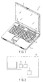
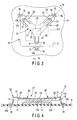
- An electronic apparatus (1) characterized by comprising:a housing (3);a substrate (6) built in the housing (3);a circuit module (8, 9) which has an element portion (13) and is mounted on the substrate (6);a heat conducting member (11) which is thermally connected to the element portion (13); anda retaining member (12) having a pressing portion (17) which is located at an opposite to the element portion (13) about the heat conducting member (11) to abut on the heat conducting member (11), and three feet (14, 15, 16) which extend from the pressing portion (17) in three directions and have respective end portions (14a, 15a, 16a) fixed on the substrate (6), said retaining member (12) urging the heat conducting member (11) toward the element portion (13).
- The electronic apparatus(1) according to claim 1, characterized in that:the heat conducting member (11) has a pair of side portions at positions which sandwiches the pressing portion (17);a first foot (14) of the three feet (14, 15, 16) extends in a direction of crossing one of the pair of side portions; anda second foot (15) and a third foot (16) of the three feet (14, 15, 16) extend in a direction of crossing the other one of the pair of side portions.
- The electronic apparatus (1) according to claim 1, characterized in that:a first foot (14) of the three feet (14, 15, 16) extends in a direction away from the element portion (13); anda second foot (15) and a third foot (16) of the three feet (14, 15, 16) extend in a direction separating from each other, along a direction crossing the extending direction of the first foot (14).
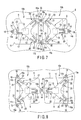
- An electronic apparatus (1) characterized by comprising:a housing (3);a substrate (6) built in the housing (3);a first circuit module (8) which has a first element portion (13) and is mounted on the substrate (6);a second circuit module (9) which has a second element portion (13) and is mounted side by side with the first circuit module (8) on the substrate (6);a first heat conducting member (11) which is thermally connected to the first element portion (13);a second heat conducting member (11) which is thermally connected to the second element portion (13);a first retaining member (12) which has a pressing portion (17) located at an opposite to the first element portion (13) about the first heat conducting member (11) to abut on the first heat conducting member (11), and three feet (14, 15, 16) extending from the pressing portion (17) in three directions and having respective end portions (14a, 15a, 16a) fixed on the substrate (6), said first retaining member (12) urging the first heat conducting member (11) toward the first element portion (13); anda second retaining member (12) which has a pressing portion (17) located at an opposite to the second element portion (13) about the second heat conducting member (11) to abut on the second heat conducting member (11), and three feet (14, 15, 16) extending from the pressing portion (17) in three directions and having respective end portions (14a, 15a, 16a) fixed on the substrate (6), said second retaining member (12) urging the second heat conducting member (11) toward the second element portion (13),wherein at least one of the three feet (14, 15, 16) in the first retaining member (12) and at least one of the three feet (14, 15, 16) in the second retaining member (12) are fixed together on the substrate (6), between the first circuit module (8) and the second circuit module (9).
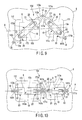
- An electronic apparatus (1) characterized by comprising:a housing (3);a substrate (6) built in the housing (3);a first circuit module (8) which has a first element portion (13a) and is mounted on the substrate (6);a second circuit module (9) which has a second element portion (13b) and is mounted side by side with the first circuit module (8) on the substrate (6);a first heat conducting member (111) which is thermally connected to the first element portion (13a);a second heat conducting member(112) which is thermally connected to the second element portion(13b);a fixing portion (23) located between the first circuit module (8) and the second circuit module (9);a first pressing portion (171) which has an end (171a) fixed on the fixing portion (23), and which has the other end (171b) fixed on the substrate (6) at a position different from the fixing portion (23) to urge the first heat conducting member (111) toward the first element portion (13a); anda second pressing portion (172) which has an end (172a) fixed on the fixing portion (23), and which has the other end (172b) fixed on the substrate (6) at a position different from the fixing portion (23) to urge the second heat conducting member (112) toward the second element portion (13b).
- The electronic apparatus (1) according to claim 5, characterized in that lines linking the other end (171b) of the first pressing portion (171) with the fixing portion (23) and linking the other end (172b) of the second pressing portion (172) with the fixing portion (23) are parallel to a line (A) linking the first element portion (13a) with the second element portion (13b).
- The electronic apparatus (1) according to any one of claims 5 and 6, characterized in that the first pressing portion (171) and the second pressing portion (172) are provided integrally as one body.
- An electronic apparatus (1) characterized by comprising:a housing (3);a substrate (6) built in the housing (3);a first circuit module (8) which is mounted on the substrate (6) and has a first element portion (13a);a second circuit module (9) which is mounted side by side with the first circuit module (8) on the substrate (6) and has a second element portion (13b);a first heat conducting member (111) which is thermally connected to the first element portion (13a);a second heat conducting member (112) which is thermally connected to the second element portion (13b);a first pressing portion (171) which has a proximal portion (171a) supported between the first circuit module (8) and the second circuit module (9), and which has a distal portion (171c) urge the first heat conducting member (111) toward the first element portion (13a); anda second pressing portion (172) which has a proximal portion (172a) supported between the first circuit module (8) and the second circuit module (9), and which has a distal portion (172c) urge the second heat conducting member (112) toward the second element portion (13b).
- The electronic apparatus (1) according to claim 8, characterized in that the first pressing portion (171) and the second pressing portion (172) are provided integrally as one body.
Applications Claiming Priority (2)
| Application Number | Priority Date | Filing Date | Title |
|---|---|---|---|
| JP2003399818A JP4387777B2 (en) | 2003-11-28 | 2003-11-28 | Electronics |
| JP2003399818 | 2003-11-28 |
Publications (3)
| Publication Number | Publication Date |
|---|---|
| EP1536467A2 true EP1536467A2 (en) | 2005-06-01 |
| EP1536467A3 EP1536467A3 (en) | 2007-06-13 |
| EP1536467B1 EP1536467B1 (en) | 2009-04-15 |
Family
ID=34463889
Family Applications (1)
| Application Number | Title | Priority Date | Filing Date |
|---|---|---|---|
| EP04028029A Active EP1536467B1 (en) | 2003-11-28 | 2004-11-25 | Retaining member and heat conducting member for electronic apparatus |
Country Status (4)
| Country | Link |
|---|---|
| US (1) | US7170750B2 (en) |
| EP (1) | EP1536467B1 (en) |
| JP (1) | JP4387777B2 (en) |
| DE (1) | DE602004020569D1 (en) |
Cited By (4)
| Publication number | Priority date | Publication date | Assignee | Title |
|---|---|---|---|---|
| FR2931523A1 (en) * | 2008-05-21 | 2009-11-27 | Fagorbrandt Sas | Component e.g. diode bridge, fixing device for use in e.g. induction cook top, has outer and inner spring blades extended in same orthogonal direction and overlapped with each other, where blades respectively maintain component in position |
| EP2445005A1 (en) * | 2010-10-22 | 2012-04-25 | Siemens Aktiengesellschaft | Cooling device with flat spring |
| WO2012113584A1 (en) * | 2011-02-22 | 2012-08-30 | Infineon Technologies Bipolar Gmbh & Co. Kg | Power semiconductor module |
| EP2927954A1 (en) * | 2014-04-02 | 2015-10-07 | Brusa Elektronik AG | Fastening system for a power module |
Families Citing this family (37)
| Publication number | Priority date | Publication date | Assignee | Title |
|---|---|---|---|---|
| WO2006112027A1 (en) * | 2005-04-15 | 2006-10-26 | Fujitsu Limited | Heat sink, circuit board and electronic device |
| US7570490B2 (en) * | 2005-08-31 | 2009-08-04 | Ati Technologies Ulc | Variable spring rate thermal management apparatus attachment mechanism |
| US7400507B2 (en) * | 2005-10-19 | 2008-07-15 | Inventec Corporation | Fastening structure |
| JP4095641B2 (en) * | 2006-01-31 | 2008-06-04 | 株式会社東芝 | Electronics |
| JP4816189B2 (en) * | 2006-03-27 | 2011-11-16 | 日本電気株式会社 | Heat dissipation structure, information device, and manufacturing method of heat dissipation structure |
| US7460371B2 (en) * | 2006-05-25 | 2008-12-02 | Agilent Technologies, Inc. | Wiffle tree components, cooling systems, and methods of attaching a printed circuit board to a heat sink |
| JP4921096B2 (en) * | 2006-09-28 | 2012-04-18 | 富士通株式会社 | Electronic equipment and cooling parts |
| US7782622B1 (en) * | 2006-10-04 | 2010-08-24 | Nvidia Corporation | Attachment apparatus for electronic boards |
| US7436673B2 (en) * | 2006-11-30 | 2008-10-14 | Inventec Corporation | Heat sink fixing assembly |
| US7554809B2 (en) * | 2007-02-09 | 2009-06-30 | Inventec Corporation | Heatsink assembly structure |
| JP2008251687A (en) | 2007-03-29 | 2008-10-16 | Toshiba Corp | Printed circuit board, and electronic equipment equipped with this |
| US7589972B2 (en) * | 2007-05-26 | 2009-09-15 | Hon Hai Precision Ind. Co., Ltd. | Electrical connector with clip mechanism |
| CN101377706B (en) * | 2007-08-31 | 2011-12-21 | 鸿富锦精密工业(深圳)有限公司 | Back board combination of heat radiator for computer |
| TWI402660B (en) * | 2007-09-28 | 2013-07-21 | Hon Hai Prec Ind Co Ltd | Bolster plate assembly for heat sink of computer and heat dissipation module with the same |
| JP2009151367A (en) * | 2007-12-18 | 2009-07-09 | Toshiba Corp | Electronic equipment |
| US7764493B2 (en) * | 2008-01-04 | 2010-07-27 | Apple Inc. | Systems and methods for cooling electronic devices using airflow dividers |
| JP2010087044A (en) | 2008-09-29 | 2010-04-15 | Toshiba Corp | Electronic apparatus |
| JP2015038897A (en) * | 2009-03-30 | 2015-02-26 | 株式会社東芝 | Electronic apparatus |
| JP2011128708A (en) * | 2009-12-15 | 2011-06-30 | Toshiba Corp | Electronic apparatus |
| JP2011166024A (en) | 2010-02-12 | 2011-08-25 | Toshiba Corp | Electronic instrument |
| US8233280B2 (en) * | 2010-03-15 | 2012-07-31 | Lincoln Global, Inc. | Electronic module with center mounting fasteners |
| JP4869419B2 (en) * | 2010-03-18 | 2012-02-08 | 株式会社東芝 | Electronics |
| JP4875181B2 (en) | 2010-04-09 | 2012-02-15 | 株式会社東芝 | Electronics |
| JP4843725B1 (en) | 2010-06-18 | 2011-12-21 | 株式会社東芝 | Television apparatus and electronic device |
| BR112013007422B1 (en) * | 2010-09-29 | 2019-11-12 | Siemens Ag | subsea control system |
| TWI514953B (en) * | 2011-08-09 | 2015-12-21 | Asustek Comp Inc | Heat-dissipating module |
| TWI538611B (en) * | 2011-11-29 | 2016-06-11 | 鴻準精密工業股份有限公司 | Heat sink and clip thereof |
| JP5242817B1 (en) | 2012-01-31 | 2013-07-24 | 株式会社東芝 | Electronics |
| JP2014016026A (en) * | 2012-06-13 | 2014-01-30 | Toyota Industries Corp | Plate spring and heat dissipation device |
| WO2014147681A1 (en) * | 2013-03-22 | 2014-09-25 | パナソニック株式会社 | Populated board, pressing member, and electronic device |
| JP6201511B2 (en) * | 2013-08-15 | 2017-09-27 | 富士通株式会社 | Electronics |
| JP6898162B2 (en) * | 2017-06-23 | 2021-07-07 | 矢崎総業株式会社 | Fixed structure of electronic components |
| US10721840B2 (en) * | 2017-10-11 | 2020-07-21 | DISH Technologies L.L.C. | Heat spreader assembly |
| TWM567398U (en) * | 2018-06-04 | 2018-09-21 | 華碩電腦股份有限公司 | Circuit board and heat dissipation device thereof |
| US11251103B2 (en) * | 2019-03-29 | 2022-02-15 | Intel Corporation | Segmented heatsink |
| JP6979095B2 (en) * | 2020-02-20 | 2021-12-08 | レノボ・シンガポール・プライベート・リミテッド | Heat transport equipment and electronics |
| US11800687B2 (en) | 2021-08-26 | 2023-10-24 | Dish Network L.L.C. | Heat transfer assembly |
Citations (2)
| Publication number | Priority date | Publication date | Assignee | Title |
|---|---|---|---|---|
| US6222734B1 (en) | 1999-11-29 | 2001-04-24 | Intel Corporation | Clamping heat sinks to circuit boards over processors |
| JP2003101272A (en) | 2001-09-21 | 2003-04-04 | Toshiba Corp | Cooling device and electronic appliance with built-in cooling device |
Family Cites Families (75)
| Publication number | Priority date | Publication date | Assignee | Title |
|---|---|---|---|---|
| WO1985003385A1 (en) * | 1984-01-23 | 1985-08-01 | La Telemecanique Electrique | Mounting and connection device for power semi-conductors |
| US5089936A (en) * | 1988-09-09 | 1992-02-18 | Hitachi, Ltd. | Semiconductor module |
| US5268817A (en) | 1990-04-27 | 1993-12-07 | Kabushiki Kaisha Toshiba | Portable computer with keyboard and having display with coordinate input tablet rotatably mounted to face either toward or away from keyboard when closed over keyboard |
| DE59406013D1 (en) * | 1993-06-07 | 1998-06-25 | Melcher Ag | FASTENING DEVICE FOR SEMICONDUCTOR SWITCHING ELEMENTS |
| JPH0749725A (en) | 1993-08-06 | 1995-02-21 | Sharp Corp | Information processor |
| JP3385482B2 (en) | 1993-11-15 | 2003-03-10 | 株式会社日立製作所 | Electronics |
| JP3392527B2 (en) | 1994-08-01 | 2003-03-31 | 富士通株式会社 | Heat sink mounting structure and fixture |
| JP3258198B2 (en) | 1995-04-28 | 2002-02-18 | 株式会社東芝 | Cooling device for circuit module and portable electronic device having this cooling device |
| JP2940642B2 (en) | 1995-06-08 | 1999-08-25 | インターナシヨナル・ビジネス・マシーンズ・コーポレーシヨン | Mechanical structure of information processing equipment |
| US6094180A (en) | 1996-04-05 | 2000-07-25 | Fakespace, Inc. | Gimbal-mounted virtual reality display system |
| JPH104161A (en) | 1996-06-14 | 1998-01-06 | Nippon Keiki Seisakusho:Kk | Heat sink mounting device |
| JPH1055227A (en) | 1996-08-09 | 1998-02-24 | Sharp Corp | Information processor |
| JPH10189843A (en) * | 1996-12-25 | 1998-07-21 | Ricoh Co Ltd | Electronic component presser metal fitting |
| JPH10261884A (en) | 1997-03-17 | 1998-09-29 | Nec Home Electron Ltd | Cooling structure for information processor |
| JPH10303582A (en) | 1997-04-22 | 1998-11-13 | Toshiba Corp | Cooing device of circuit module and portable information equipment mounting circuit module |
| JPH1139058A (en) | 1997-07-14 | 1999-02-12 | Ricoh Co Ltd | Pen input type electronic unit |
| US6005767A (en) | 1997-11-14 | 1999-12-21 | Vadem | Portable computer having articulated display |
| US20020053421A1 (en) | 1997-09-10 | 2002-05-09 | Kabushiki Kaisha Toshiba | Heat dissipating structure for electronic apparatus |
| KR100286375B1 (en) | 1997-10-02 | 2001-04-16 | 윤종용 | Radiator of electronic system and computer system having the same |
| US6049459A (en) * | 1997-11-17 | 2000-04-11 | Lucent Technologies, Inc. | Nesting clamps for electrical components |
| JPH11166500A (en) | 1997-12-03 | 1999-06-22 | Toshiba Ave Co Ltd | Pump |
| US6464195B1 (en) | 1997-12-04 | 2002-10-15 | Raymond Hildebrandt | Ergonomic mounting for computer screen displays |
| JP3366244B2 (en) | 1998-02-04 | 2003-01-14 | 富士通株式会社 | Electronics |
| JP4128660B2 (en) | 1998-07-27 | 2008-07-30 | 株式会社東芝 | Electronics |
| US6282082B1 (en) | 1998-07-31 | 2001-08-28 | Qubit, Llc | Case for a modular tablet computer system |
| US6377452B1 (en) | 1998-12-18 | 2002-04-23 | Furukawa Electric Co., Ltd. | Heat pipe hinge structure for electronic device |
| US6483445B1 (en) | 1998-12-21 | 2002-11-19 | Intel Corporation | Electronic device with hidden keyboard |
| GB2348459B (en) | 1999-03-27 | 2003-03-19 | Ibm | Lid restraint for portable computer |
| US6231371B1 (en) | 1999-06-25 | 2001-05-15 | Hewlett-Packard Company | Docking station for multiple devices |
| JP4270667B2 (en) | 1999-08-17 | 2009-06-03 | 株式会社東芝 | Circuit component cooling device and electronic device |
| JP3283853B2 (en) | 1999-09-17 | 2002-05-20 | 米沢日本電気株式会社 | Docking station |
| US6166907A (en) | 1999-11-26 | 2000-12-26 | Chien; Chuan-Fu | CPU cooling system |
| US6196850B1 (en) | 2000-02-10 | 2001-03-06 | International Business Machines Corporation | Rotatable docking station for an electronic device |
| JP2001230356A (en) | 2000-02-17 | 2001-08-24 | Showa Denko Kk | Radiator with clip |
| JP2001251079A (en) | 2000-03-03 | 2001-09-14 | Diamond Electric Mfg Co Ltd | Method for producing heat sink using heat pipe and method for producing heat pipe |
| US6418017B1 (en) | 2000-03-30 | 2002-07-09 | Hewlett-Packard Company | Heat dissipating chassis member |
| US6430038B1 (en) | 2000-04-18 | 2002-08-06 | Hewlett-Packard Company | Computer with articulated mechanism |
| US6437973B1 (en) | 2000-04-18 | 2002-08-20 | Hewlett-Packard Company | Modular mechanism for movable display |
| US6313990B1 (en) | 2000-05-25 | 2001-11-06 | Kioan Cheon | Cooling apparatus for electronic devices |
| JP3302350B2 (en) | 2000-06-29 | 2002-07-15 | 株式会社東芝 | Electronics |
| US6296048B1 (en) | 2000-09-08 | 2001-10-02 | Powerwave Technologies, Inc. | Heat sink assembly |
| JP2002099356A (en) | 2000-09-21 | 2002-04-05 | Toshiba Corp | Cooling device for electronic equipment and electronic equipment |
| US6469893B1 (en) * | 2000-09-29 | 2002-10-22 | Intel Corporation | Direct heatpipe attachment to die using center point loading |
| US6396687B1 (en) | 2000-10-13 | 2002-05-28 | Dell Products, L.P. | Rotating portable computer docking station |
| JP3607608B2 (en) | 2000-12-19 | 2005-01-05 | 株式会社日立製作所 | Liquid cooling system for notebook computers |
| US6717798B2 (en) | 2001-03-22 | 2004-04-06 | Intel Corporation | Docking digital picture displays |
| US20020141159A1 (en) | 2001-03-29 | 2002-10-03 | Bloemen James Andrew | Sealed and passively cooled telecommunications customer service terminal |
| JP2002344186A (en) | 2001-05-15 | 2002-11-29 | Sharp Corp | Electronic equipment |
| JP2002353670A (en) | 2001-05-25 | 2002-12-06 | Toshiba Home Technology Corp | Heat sink |
| FR2827115B1 (en) | 2001-07-06 | 2003-09-05 | Alstom | BOX FOR POWER CONVERTER |
| TW558611B (en) | 2001-07-18 | 2003-10-21 | Matsushita Electric Ind Co Ltd | Small pump, cooling system and portable equipment |
| US6873521B2 (en) | 2001-07-24 | 2005-03-29 | Hewlett-Packard Development Company, L.P. | Multiple environment foldable computer |
| US6480373B1 (en) | 2001-07-24 | 2002-11-12 | Compaq Information Technologies Group, L.P. | Multifunctional foldable computer |
| JP2003044169A (en) | 2001-07-31 | 2003-02-14 | Casio Comput Co Ltd | Electronic equipment |
| JP4512296B2 (en) | 2001-08-22 | 2010-07-28 | 株式会社日立製作所 | Liquid cooling system for portable information processing equipment |
| JP3925126B2 (en) | 2001-08-28 | 2007-06-06 | 日産自動車株式会社 | Fuel cell |
| JP2003078270A (en) | 2001-09-07 | 2003-03-14 | Hitachi Ltd | Electronic apparatus |
| JP3946018B2 (en) | 2001-09-18 | 2007-07-18 | 株式会社日立製作所 | Liquid-cooled circuit device |
| JP3741092B2 (en) | 2001-09-25 | 2006-02-01 | 松下電器産業株式会社 | Ultra-thin pump and cooling system equipped with it |
| JP2003223238A (en) | 2002-01-28 | 2003-08-08 | Internatl Business Mach Corp <Ibm> | Computer device, monitor unit and support structure of unit facing user |
| JP3961843B2 (en) | 2002-02-08 | 2007-08-22 | 株式会社日立製作所 | A small computer with a liquid cooling system. |
| JP3431024B1 (en) | 2003-01-15 | 2003-07-28 | 松下電器産業株式会社 | Cooling system |
| JP3452059B1 (en) | 2002-05-15 | 2003-09-29 | 松下電器産業株式会社 | Cooling device and electronic equipment equipped with it |
| JP4168669B2 (en) | 2002-05-31 | 2008-10-22 | 松下電工株式会社 | Thin pump |
| DE10225993A1 (en) * | 2002-06-12 | 2003-12-24 | Bosch Gmbh Robert | heatsink |
| US6856506B2 (en) | 2002-06-19 | 2005-02-15 | Motion Computing | Tablet computing device with three-dimensional docking support |
| KR100891994B1 (en) * | 2002-06-20 | 2009-04-08 | 삼성전자주식회사 | Heatsink fixing apparatus |
| US6788530B2 (en) | 2002-09-24 | 2004-09-07 | International Business Machines Corporation | User friendly computer equipment, monitor unit, and monitor unit setting base |
| EP1333492B1 (en) * | 2002-11-08 | 2006-03-01 | Agilent Technologies Inc. a Delaware Corporation | Cooling a microchip on a circuit board |
| JP2003216278A (en) | 2002-12-10 | 2003-07-31 | Toshiba Corp | Electronic device |
| JP2004348650A (en) | 2003-05-26 | 2004-12-09 | Toshiba Corp | Electronic device |
| US7035090B2 (en) | 2003-09-04 | 2006-04-25 | Kabushiki Kaisha Toshiba | Interlocking mechanism for a display |
| JP2005107122A (en) | 2003-09-30 | 2005-04-21 | Toshiba Corp | Electronic equipment |
| JP2005190316A (en) | 2003-12-26 | 2005-07-14 | Toshiba Corp | Electronic device |
| US7095614B2 (en) * | 2004-04-20 | 2006-08-22 | International Business Machines Corporation | Electronic module assembly |
-
2003
- 2003-11-28 JP JP2003399818A patent/JP4387777B2/en not_active Expired - Lifetime
-
2004
- 2004-11-22 US US10/994,938 patent/US7170750B2/en active Active
- 2004-11-25 DE DE602004020569T patent/DE602004020569D1/en active Active
- 2004-11-25 EP EP04028029A patent/EP1536467B1/en active Active
Patent Citations (2)
| Publication number | Priority date | Publication date | Assignee | Title |
|---|---|---|---|---|
| US6222734B1 (en) | 1999-11-29 | 2001-04-24 | Intel Corporation | Clamping heat sinks to circuit boards over processors |
| JP2003101272A (en) | 2001-09-21 | 2003-04-04 | Toshiba Corp | Cooling device and electronic appliance with built-in cooling device |
Cited By (5)
| Publication number | Priority date | Publication date | Assignee | Title |
|---|---|---|---|---|
| FR2931523A1 (en) * | 2008-05-21 | 2009-11-27 | Fagorbrandt Sas | Component e.g. diode bridge, fixing device for use in e.g. induction cook top, has outer and inner spring blades extended in same orthogonal direction and overlapped with each other, where blades respectively maintain component in position |
| EP2445005A1 (en) * | 2010-10-22 | 2012-04-25 | Siemens Aktiengesellschaft | Cooling device with flat spring |
| WO2012113584A1 (en) * | 2011-02-22 | 2012-08-30 | Infineon Technologies Bipolar Gmbh & Co. Kg | Power semiconductor module |
| EP2927954A1 (en) * | 2014-04-02 | 2015-10-07 | Brusa Elektronik AG | Fastening system for a power module |
| US9497876B2 (en) | 2014-04-02 | 2016-11-15 | Brusa Elektronik Ag | Fastening systems for power modules |
Also Published As
| Publication number | Publication date |
|---|---|
| JP2005166715A (en) | 2005-06-23 |
| EP1536467B1 (en) | 2009-04-15 |
| JP4387777B2 (en) | 2009-12-24 |
| EP1536467A3 (en) | 2007-06-13 |
| US7170750B2 (en) | 2007-01-30 |
| US20050117307A1 (en) | 2005-06-02 |
| DE602004020569D1 (en) | 2009-05-28 |
Similar Documents
| Publication | Publication Date | Title |
|---|---|---|
| EP1536467A2 (en) | Retaining member and heat conducting member for electronic apparatus | |
| US8125783B2 (en) | Printed circuit board and electronic apparatus | |
| US5557500A (en) | Heat dissipating arrangement in a portable computer | |
| US7674985B2 (en) | Printed wiring board assembly, method of mounting components on printed wiring board and electronic apparatus | |
| US7091586B2 (en) | Detachable on package voltage regulation module | |
| EP2472352A2 (en) | Cooling apparatus and electronic apparatus | |
| JP2001345405A (en) | Circuit module and electronic equipment mounting circuit module | |
| US20080130234A1 (en) | Electronic Apparatus | |
| US9357676B2 (en) | Cooling device and electronic apparatus | |
| US20050286229A1 (en) | Modular heat-dissipation assembly structure for a PCB | |
| US7333342B2 (en) | Fastening of a member pressing a heat sink against a component mounted on a circuit board | |
| US7110257B2 (en) | Electronic apparatus including printed wiring board provided with heat generating component | |
| US20100079951A1 (en) | Electronic apparatus | |
| JP2006114860A (en) | Heat sink device | |
| JP2008299628A (en) | Electronic equipment and cooling unit | |
| JP2009181215A (en) | Electronic equipment | |
| JP4956575B2 (en) | Electronics | |
| US20080192439A1 (en) | Heatsink assembly structure | |
| JP2010021379A (en) | Electronic equipment | |
| US6064570A (en) | Computer processor/heat sink assembly having a dual direction air flow path | |
| JPH1098287A (en) | Cooler for circuit board module and portable electronic equipment having the cooler | |
| US7864535B2 (en) | Electronic device | |
| WO2021186797A1 (en) | Circuit board module | |
| CN1745608A (en) | Heat dissipating arrangement for an electronic appliance | |
| US20230011922A1 (en) | Circuit board module |
Legal Events
| Date | Code | Title | Description |
|---|---|---|---|
| PUAI | Public reference made under article 153(3) epc to a published international application that has entered the european phase |
Free format text: ORIGINAL CODE: 0009012 |
|
| 17P | Request for examination filed |
Effective date: 20041125 |
|
| AK | Designated contracting states |
Kind code of ref document: A2 Designated state(s): AT BE BG CH CY CZ DE DK EE ES FI FR GB GR HU IE IS IT LI LU MC NL PL PT RO SE SI SK TR |
|
| AX | Request for extension of the european patent |
Extension state: AL HR LT LV MK YU |
|
| PUAL | Search report despatched |
Free format text: ORIGINAL CODE: 0009013 |
|
| AK | Designated contracting states |
Kind code of ref document: A3 Designated state(s): AT BE BG CH CY CZ DE DK EE ES FI FR GB GR HU IE IS IT LI LU MC NL PL PT RO SE SI SK TR |
|
| AX | Request for extension of the european patent |
Extension state: AL HR LT LV MK YU |
|
| RIC1 | Information provided on ipc code assigned before grant |
Ipc: H05K 3/30 20060101ALI20070508BHEP Ipc: H01L 23/40 20060101AFI20050304BHEP |
|
| 17Q | First examination report despatched |
Effective date: 20070926 |
|
| AKX | Designation fees paid |
Designated state(s): DE FR GB |
|
| GRAP | Despatch of communication of intention to grant a patent |
Free format text: ORIGINAL CODE: EPIDOSNIGR1 |
|
| GRAS | Grant fee paid |
Free format text: ORIGINAL CODE: EPIDOSNIGR3 |
|
| GRAA | (expected) grant |
Free format text: ORIGINAL CODE: 0009210 |
|
| AK | Designated contracting states |
Kind code of ref document: B1 Designated state(s): DE FR GB |
|
| REG | Reference to a national code |
Ref country code: GB Ref legal event code: FG4D |
|
| REF | Corresponds to: |
Ref document number: 602004020569 Country of ref document: DE Date of ref document: 20090528 Kind code of ref document: P |
|
| PLBE | No opposition filed within time limit |
Free format text: ORIGINAL CODE: 0009261 |
|
| STAA | Information on the status of an ep patent application or granted ep patent |
Free format text: STATUS: NO OPPOSITION FILED WITHIN TIME LIMIT |
|
| 26N | No opposition filed |
Effective date: 20100118 |
|
| REG | Reference to a national code |
Ref country code: FR Ref legal event code: PLFP Year of fee payment: 12 |
|
| REG | Reference to a national code |
Ref country code: FR Ref legal event code: PLFP Year of fee payment: 13 |
|
| REG | Reference to a national code |
Ref country code: FR Ref legal event code: PLFP Year of fee payment: 14 |
|
| REG | Reference to a national code |
Ref country code: FR Ref legal event code: PLFP Year of fee payment: 15 |
|
| REG | Reference to a national code |
Ref country code: DE Ref legal event code: R082 Ref document number: 602004020569 Country of ref document: DE Representative=s name: HENKEL & PARTNER MBB PATENTANWALTSKANZLEI, REC, DE Ref country code: DE Ref legal event code: R082 Ref document number: 602004020569 Country of ref document: DE Representative=s name: PATENTANWAELTE HENKEL, BREUER & PARTNER MBB, DE Ref country code: DE Ref legal event code: R081 Ref document number: 602004020569 Country of ref document: DE Owner name: TOSHIBA CLIENT SOLUTIONS CO., LTD., JP Free format text: FORMER OWNER: KABUSHIKI KAISHA TOSHIBA, TOKIO/TOKYO, JP |
|
| REG | Reference to a national code |
Ref country code: GB Ref legal event code: 732E Free format text: REGISTERED BETWEEN 20190110 AND 20190116 |
|
| PGFP | Annual fee paid to national office [announced via postgrant information from national office to epo] |
Ref country code: GB Payment date: 20231123 Year of fee payment: 20 |
|
| PGFP | Annual fee paid to national office [announced via postgrant information from national office to epo] |
Ref country code: FR Payment date: 20231120 Year of fee payment: 20 Ref country code: DE Payment date: 20231121 Year of fee payment: 20 |