EP1536219A2 - Vorrichtung zum Anbringen von Ausgleichsgewichten an Kraftfahrzeugreifen in Reifen-Auswuchtmachinen - Google Patents
Vorrichtung zum Anbringen von Ausgleichsgewichten an Kraftfahrzeugreifen in Reifen-Auswuchtmachinen Download PDFInfo
- Publication number
- EP1536219A2 EP1536219A2 EP04026733A EP04026733A EP1536219A2 EP 1536219 A2 EP1536219 A2 EP 1536219A2 EP 04026733 A EP04026733 A EP 04026733A EP 04026733 A EP04026733 A EP 04026733A EP 1536219 A2 EP1536219 A2 EP 1536219A2
- Authority
- EP
- European Patent Office
- Prior art keywords
- gear
- gears
- wheel
- indicator element
- balancing
- Prior art date
- Legal status (The legal status is an assumption and is not a legal conclusion. Google has not performed a legal analysis and makes no representation as to the accuracy of the status listed.)
- Granted
Links
Images

Classifications
-
- G—PHYSICS
- G01—MEASURING; TESTING
- G01M—TESTING STATIC OR DYNAMIC BALANCE OF MACHINES OR STRUCTURES; TESTING OF STRUCTURES OR APPARATUS, NOT OTHERWISE PROVIDED FOR
- G01M1/00—Testing static or dynamic balance of machines or structures
- G01M1/30—Compensating imbalance
- G01M1/32—Compensating imbalance by adding material to the body to be tested, e.g. by correcting-weights
- G01M1/326—Compensating imbalance by adding material to the body to be tested, e.g. by correcting-weights the body being a vehicle wheel
-
- G—PHYSICS
- G01—MEASURING; TESTING
- G01M—TESTING STATIC OR DYNAMIC BALANCE OF MACHINES OR STRUCTURES; TESTING OF STRUCTURES OR APPARATUS, NOT OTHERWISE PROVIDED FOR
- G01M1/00—Testing static or dynamic balance of machines or structures
- G01M1/02—Details of balancing machines or devices
-
- Y—GENERAL TAGGING OF NEW TECHNOLOGICAL DEVELOPMENTS; GENERAL TAGGING OF CROSS-SECTIONAL TECHNOLOGIES SPANNING OVER SEVERAL SECTIONS OF THE IPC; TECHNICAL SUBJECTS COVERED BY FORMER USPC CROSS-REFERENCE ART COLLECTIONS [XRACs] AND DIGESTS
- Y10—TECHNICAL SUBJECTS COVERED BY FORMER USPC
- Y10T—TECHNICAL SUBJECTS COVERED BY FORMER US CLASSIFICATION
- Y10T29/00—Metal working
- Y10T29/53—Means to assemble or disassemble
- Y10T29/53022—Means to assemble or disassemble with means to test work or product
-
- Y—GENERAL TAGGING OF NEW TECHNOLOGICAL DEVELOPMENTS; GENERAL TAGGING OF CROSS-SECTIONAL TECHNOLOGIES SPANNING OVER SEVERAL SECTIONS OF THE IPC; TECHNICAL SUBJECTS COVERED BY FORMER USPC CROSS-REFERENCE ART COLLECTIONS [XRACs] AND DIGESTS
- Y10—TECHNICAL SUBJECTS COVERED BY FORMER USPC
- Y10T—TECHNICAL SUBJECTS COVERED BY FORMER US CLASSIFICATION
- Y10T29/00—Metal working
- Y10T29/53—Means to assemble or disassemble
- Y10T29/53039—Means to assemble or disassemble with control means energized in response to activator stimulated by condition sensor
- Y10T29/53061—Responsive to work or work-related machine element
-
- Y—GENERAL TAGGING OF NEW TECHNOLOGICAL DEVELOPMENTS; GENERAL TAGGING OF CROSS-SECTIONAL TECHNOLOGIES SPANNING OVER SEVERAL SECTIONS OF THE IPC; TECHNICAL SUBJECTS COVERED BY FORMER USPC CROSS-REFERENCE ART COLLECTIONS [XRACs] AND DIGESTS
- Y10—TECHNICAL SUBJECTS COVERED BY FORMER USPC
- Y10T—TECHNICAL SUBJECTS COVERED BY FORMER US CLASSIFICATION
- Y10T29/00—Metal working
- Y10T29/53—Means to assemble or disassemble
- Y10T29/53087—Means to assemble or disassemble with signal, scale, illuminator, or optical viewer
-
- Y—GENERAL TAGGING OF NEW TECHNOLOGICAL DEVELOPMENTS; GENERAL TAGGING OF CROSS-SECTIONAL TECHNOLOGIES SPANNING OVER SEVERAL SECTIONS OF THE IPC; TECHNICAL SUBJECTS COVERED BY FORMER USPC CROSS-REFERENCE ART COLLECTIONS [XRACs] AND DIGESTS
- Y10—TECHNICAL SUBJECTS COVERED BY FORMER USPC
- Y10T—TECHNICAL SUBJECTS COVERED BY FORMER US CLASSIFICATION
- Y10T29/00—Metal working
- Y10T29/53—Means to assemble or disassemble
- Y10T29/53448—Vehicle wheel
Definitions
- the present invention relates to a device for applying balancing weights to vehicle wheels in wheel balancing machines.
- balancing machines that support the wheels to be balanced so that they can rotate about an axis, the machines being provided with electronic means that are suitable to detect any relative imbalances between the two sides of said wheels.
- each balancing machine comprises rectilinear guiding means, which are parallel to the wheel rotation axis and on which an indicator element, provided with an end that acts as a reference and can be inserted in the rim, can slide.
- the operator slides the indicator element until said end is alternatively arranged in two reference points chosen inside the rim, so as to define two planes that are perpendicular to the rotation axis and are conventionally termed "compensation planes".
- the electronic means of the machine by turning the wheel, measure the imbalance with respect to the compensation planes and provide, once this measurement has been completed, the values of the weights that must be applied to the wheel at said planes.
- the indicator element has to be repositioned at the two reference positions in order to allow the operator to apply the weights to the rim, for example by means of an elastic clamp, which is fitted on the indicator element at the end that acts as a reference.
- wheel balancing machines are provided with particular devices that are suitable to detect the current location of said element with respect to the rectilinear guiding means and automatically lock its translational motion when, during the third step, it has been returned to said preset positions.
- These devices are commonly provided with rack elements and/or with toothed transmission belts, which are associated with the sliding indicator element and can be locked by means of a conventional detent mechanism, which is operated when one of the preset positions is reached.
- the aim of the present invention is to eliminate the above-noted drawbacks of the background art, by providing a device for applying balancing weights to vehicle wheels in wheel balancing machines that is particularly simple to manufacture and to fit to a balancing machine, with low manufacturing costs that do not affect significantly the overall cost of said machines.
- an object of the present invention is to be particularly compact and small and at the same time sturdy.
- Another object of the present invention is to be applicable to any type of wheel balancing machine.
- Another object of the present invention is to provide a device that is simple, relatively easy to provide in practice, safe in use, effective in operation, and has a relatively low cost.
- the present device for applying balancing weights to vehicle wheels in wheel balancing machines, which comprises means for detecting the position of an indicator element that can slide on rectilinear guiding means with respect to a vehicle wheel that is supported so that it can rotate on the frame of a wheel balancing machine, and means for the removable locking of said indicator element in at least one direction of sliding on said rectilinear guiding means, said removable locking means being activated when a preset position of said indicator element on said rectilinear guiding means is reached, characterized in that said removable locking means comprise at least one first gear and one second gear, which are supported so that they can rotate on said wheel balancing machine and mesh with each other, means for transmitting the motion of said indicator element to said first gear, and means for moving a third gear between an inactive configuration, in which said third gear is disengaged from said first and second gears, and a locking configuration, in which said third gear is simultaneously engaged with the sets of teeth of said first
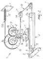
- the reference numeral 1 generally designates a device for applying balancing weights to vehicle wheels in wheel balancing machines.
- the device 1 is fitted on a conventional wheel balancing machine M, which is provided with a shaft A on which it is possible to key a vehicle wheel, which is not shown in the figure because it is of a known type, and can be made to rotate about its own axis.
- the wheel balancing machine M is provided with conventional electronic means E adapted to assess any imbalance of the wheel with respect to the rotation axis of the shaft A.
- the device 1 comprises sensing means 2 for detecting the position, with respect to the wheel, of an indicator element 3 that can slide on rectilinear guiding means 4.
- Such rectilinear guiding means are constituted by a hollow cylinder 5, which is associated with a frame T of the wheel balancing machine M; the indicator element 3 instead comprises an arm 6, which can slide telescopically inside said hollow cylinder.
- the hollow cylinder 5 is parallel to the axis of the shaft A and lies at a distance from said shaft that is substantially shorter than the radius of the rim of the wheel supported on the balancing machine M, thus allowing to move the arm 6 until it lies inside said rim.
- the indicator element 3 is provided with a lever 7, which is associated with the free end of the arm 6 and can rotate about the axis of the hollow cylinder 5; said lever can be provided with a clamp, not shown because it is of a known type, for applying balancing weights to the wheel rim.
- the device 1 comprises means 8 for removably locking the sliding of the indicator element 3 on the rectilinear guiding means 4 toward the wheel; said means are such that they are activated when the indicator element reaches a preset position on said guiding means.
- the removable locking means 8 comprise a first gear 9a and a second gear 9b, which are supported so that they can rotate on the frame T and mesh with each other; said gears have the same number of teeth, and their pitch circles are substantially identical.
- the removable locking means 8 comprise means 10 for transmitting the motion of the indicator element 3 to the first gear 9a, which are advantageously of the flexible type and comprise a flexible element constituted for example by a cable 11 or the like.
- a first end 11a of said cable is associated with the arm 6, while a second end 11b, which is opposite to the first one, is connected to the frame T by interposing elastic means, such as for example a return spring 12 or the like.
- the cable 11 is at least partially wound on a pulley 13, which is rigidly and coaxially associated with the first gear 9a and whose diameter is substantially larger than the diameter of the pitch circle of the first gear; the winding of the flexible element around the pulley 13, in particular, is such as to not allow relative slippage between the cable 11 and the peripheral portion of said pulley.
- the transmission means 10 may comprise one or more pulleys 14 for guiding the cable 11, which are supported on the frame T so that they can rotate about their own axis; said guiding pulleys are suitable to flex the cable 11 while keeping it under tension, forming a path inside the balancing machine M that is free from obstacles or hindrances for the flexible element.
- the removable locking means 8 are provided with means 15 for moving a third gear 9c between an inactive configuration, in which it is disengaged from the first gear 9a and from the second gear 9b, and a locking configuration, in which it simultaneously engages the teeth of the first and second gears 9a and 9b, so as to prevent their rotation.
- the third gear 9c in particular, has a pitch circle diameter that is substantially smaller than that of the other two gears 9a and 9b.
- the movement means 15 comprise a first portion 16a, which is associated with the frame T, and a second portion 16b, which rotatably supports the third gear 9c and can move toward and away from the first and second gears 9a and 9b, in the direction indicated by the arrow F in Figure 2.
- Said first and second portions are preferably constituted by the mutually movable parts of an electromagnet.
- the direction F along which the second portion 16b can move is substantially perpendicular to the plane of arrangement of the rotation axes of the first and second gears 9a and 9b.
- the electromagnet lies on the opposite side relative to the portion of the cable 11 that ends, starting from the pulley 13, with the second end 11b.
- the sensing means 2 comprise a potentiometer, which is arranged at the rotation axis of the second gear 9b in order to detect its angular position.
- the device 1 comprises a processing unit, which is provided with an input that is associated with the sensing means 2 and with an output that is associated with the removable locking means 8 and is suitable to store the preset position of the indicator element 3 on the rectilinear guiding means 4 and to actuate the movement means 15: said processing unit is preferably formed by said electronic means E suitable to evaluate the imbalance of the wheel.
- the device 1 in order to store the preset position, the device 1 is provided with a control switch; when said switch is operated, the processing unit acquires and stores the position sensed at the same instant by the sensing means 2.
- Such control switch may be of the keypad/pedal type, which can be operated directly by the operator, or of an automatic type with a timer, in which case its activation is performed by the operator by keeping motionless, for a preset period of time, the indicator element in the position that he wishes to store.
- the operation of the present invention is as follows: during the first step of the balancing operation, intended to define the so-called compensation planes, the third gear 9c is arranged in the inactive configuration, allowing the operator to move the bar 6 inside the hollow cylinder 5 by gently pushing the indicator element 3.
- the arm 6 is left fully inserted in the hollow cylinder 5.
- the repositioning of the indicator element 3 inside the rim instead activates the movement means 15; in particular, when the preset positions are reached, the electromagnet arranges the third gear 9c in the locking configuration.
- Pushing the indicator element 3 further toward the wheel increases the stability of the locking action, since it forces the three gears 9a, 9b and 9c to mutually interlock more rigidly and firmly.
- the indicator element 3 is released by the operator and retracted into the hollow cylinder 5 under the action of the return spring 12; this action of the elastic means, in particular, produces the rotation of the first and second gears 9a and 9b in the direction that produces the disengagement of the third gear 9c, which is automatically moved away from them, returning to an inactive configuration.
- the described invention achieves the proposed aim and objects, and in particular the fact is stressed that it has a structure that is simple and easy to provide and also has a low cost and compact dimensions, in addition to being particularly sturdy and reliable in operation.
- the present invention can be applied universally to any type of balancing machine; it is in fact noted that the use of guiding pulleys suitable to form an obstacle-free path for the cable allows to fit the locking means on any portion of the machine, further allowing to limit its overall dimensions.
Landscapes
- Physics & Mathematics (AREA)
- General Physics & Mathematics (AREA)
- Testing Of Balance (AREA)
- Gears, Cams (AREA)
Applications Claiming Priority (2)
| Application Number | Priority Date | Filing Date | Title |
|---|---|---|---|
| ITMO20030320 | 2003-11-25 | ||
| IT000320A ITMO20030320A1 (it) | 2003-11-25 | 2003-11-25 | Dispositivo per macchine equilibratrici per l'applicazione |
Publications (3)
| Publication Number | Publication Date |
|---|---|
| EP1536219A2 true EP1536219A2 (de) | 2005-06-01 |
| EP1536219A3 EP1536219A3 (de) | 2006-08-30 |
| EP1536219B1 EP1536219B1 (de) | 2012-10-24 |
Family
ID=34452272
Family Applications (1)
| Application Number | Title | Priority Date | Filing Date |
|---|---|---|---|
| EP04026733A Expired - Lifetime EP1536219B1 (de) | 2003-11-25 | 2004-11-10 | Vorrichtung zum Anbringen von Ausgleichsgewichten an Kraftfahrzeugreifen in Reifen-Auswuchtmachinen |
Country Status (4)
| Country | Link |
|---|---|
| US (1) | US7237326B2 (de) |
| EP (1) | EP1536219B1 (de) |
| CN (1) | CN100526826C (de) |
| IT (1) | ITMO20030320A1 (de) |
Families Citing this family (11)
| Publication number | Priority date | Publication date | Assignee | Title |
|---|---|---|---|---|
| KR100656612B1 (ko) * | 2005-10-11 | 2006-12-11 | 기아자동차주식회사 | 휠의 스티커웨이트 가압기 |
| USD570888S1 (en) * | 2005-11-21 | 2008-06-10 | Hunter Engineering Company | Vehicle wheel balancer console bezel |
| DE102007014461B4 (de) * | 2007-01-02 | 2012-03-29 | Schenck Rotec Gmbh | Verfahren und Vorrichtung zum Unwuchtausgleich von Fahrzeugrädern |
| CN102081004B (zh) * | 2010-12-21 | 2013-05-22 | 奇瑞汽车股份有限公司 | 一种轮胎装配平衡块防错系统及其控制方法 |
| US9032793B1 (en) * | 2012-03-06 | 2015-05-19 | Horizon, Llc | Wheel balancer |
| EP2792903B1 (de) * | 2013-04-19 | 2015-10-14 | WEGMANN automotive GmbH & Co. KG | Automatischer Spender für Gewichtsausgleich |
| CN109073493A (zh) * | 2016-02-29 | 2018-12-21 | 普罗姆贝科有限责任公司 | 平衡块施加机及其使用方法 |
| CN108731967B (zh) * | 2017-04-13 | 2022-05-24 | 徕卡显微系统(上海)有限公司 | 质量平衡装置及具有其的旋转式切片机 |
| CN108673373A (zh) * | 2018-05-24 | 2018-10-19 | 中信戴卡股份有限公司 | 一种轮毂表面贴平衡块的夹具 |
| CN110142593B (zh) * | 2019-06-19 | 2021-03-05 | 重庆长安民生物流股份有限公司 | 轮胎铅块压装机压装铅块的压装方法 |
| CN110125660B (zh) * | 2019-06-19 | 2021-03-05 | 重庆长安民生物流股份有限公司 | 轮胎铅块压装机 |
Family Cites Families (28)
| Publication number | Priority date | Publication date | Assignee | Title |
|---|---|---|---|---|
| US2696108A (en) * | 1951-01-12 | 1954-12-07 | Hrebicek James | Balancing machine |
| US3319470A (en) * | 1964-06-19 | 1967-05-16 | Gen Motors Corp | Balancing system |
| AU427621B2 (en) * | 1968-09-17 | 1972-08-28 | Repco Research Proprietary Limited | Improvements in or relating to apparatus for use in balancing motor vehicle and other wheels |
| US3623208A (en) * | 1969-09-23 | 1971-11-30 | Hofmann Maschf Dionys | Method and apparatus for automatic balancing of motor vehicle wheels |
| US3748910A (en) * | 1969-09-23 | 1973-07-31 | Diouys Hofmann Gmbh | Method and apparatus for automatic balancing of motor vehicle wheels |
| AU534527B2 (en) * | 1978-05-19 | 1984-02-02 | Sun Electric Corporation | Wheel balancing machine/o/ |
| US4341119A (en) * | 1980-03-18 | 1982-07-27 | Nortron Corporation | Data input system for dynamic balancing machine |
| US4635481A (en) * | 1982-07-06 | 1987-01-13 | Curchod Donald B | Light weight dynamic wheel balancing machine |
| DE3316945A1 (de) * | 1983-05-09 | 1984-11-15 | Gebr. Hofmann GmbH & Co KG, Maschinenfabrik, 6102 Pfungstadt | Vorrichtung zum automatischen einsetzen von ausgleichsgewichten an kraftfahrzeugraedern beim auswuchten derselben |
| US4903398A (en) * | 1987-02-24 | 1990-02-27 | Mazda Motor Corporation | Balance weight fitting apparatus |
| US5134766A (en) * | 1987-04-16 | 1992-08-04 | Ransburg Corporation | Automatic weight application machine |
| US5189912A (en) * | 1988-09-07 | 1993-03-02 | Interbalco Ag | Ultrasonic wheel measuring apparatus and wheel balancer incorporating same |
| JP3159474B2 (ja) * | 1991-06-20 | 2001-04-23 | 国際計測器株式会社 | タイヤホイールのバランスウェイト装着装置 |
| US5311777A (en) * | 1992-09-28 | 1994-05-17 | Hennessy Technology Corporation | Wheel balancer with adjustable operator pod |
| CN2156495Y (zh) * | 1992-09-29 | 1994-02-16 | 黄东烁 | 车轮平衡测试仪 |
| ATE172026T1 (de) * | 1993-09-07 | 1998-10-15 | Hofmann Werkstatt Technik | Verfahren und vorrichtung zum unwuchtausgleich an einem kraftfahrzeugrad mit hilfe von wenigstens einem ausgleichsgewicht |
| DE4415930C2 (de) * | 1994-05-05 | 1999-05-12 | Hofmann Werkstatt Technik | Vorrichtung zum Befestigen eines eine Klebeschicht aufweisenden Ausgleichsgewichts an einer Unwuchtausgleichsstelle eines Scheibenrades eines Kraftfahrzeugrades |
| DE4426482C2 (de) * | 1994-07-26 | 1999-09-23 | Hofmann Werkstatt Technik | Vorrichtung zum Ausgleich der Unwucht eines Kraftfahrzeugrades |
| WO1998010261A1 (en) * | 1996-09-06 | 1998-03-12 | Snap-On Equipment Europe Limited | A wheel balancer |
| US5969247A (en) * | 1998-01-08 | 1999-10-19 | Wheel Service Equipment Corporation | Electronic wheel balancer with variable speed operation, improved operator interface, and auxiliary storage |
| DE10006176A1 (de) * | 2000-02-11 | 2001-08-16 | Schenck Rotec Gmbh | Vorrichtung zum Befestigen von Ausgleichsgewichten zum Umwuchtausgleich |
| US6484574B1 (en) * | 2000-11-08 | 2002-11-26 | Hünter Engineering Company | Wheel balancer apparatus with improved imbalance correction weight positioning |
| EP1417467A4 (de) * | 2001-07-05 | 2007-06-27 | Schenck Rotec Corp | Selbstkalibrierende maschinen zum ausgleichen von arbeitsstücken und verfahren zur maschinenkalibrierung |
| WO2005008207A2 (en) * | 2003-07-14 | 2005-01-27 | Lance Okada | Lateral wheel balancing apparatuses and methods for lateral wheel balancing |
| US6983656B2 (en) * | 2003-12-22 | 2006-01-10 | Snap-On Incorporated | Method and apparatus for automotive rim edge analysis and corrective weight selection guide |
| US20050229702A1 (en) * | 2004-04-14 | 2005-10-20 | Illinois Tool Works, Inc. | Tire weight applying apparatus |
| US7448267B2 (en) * | 2004-04-14 | 2008-11-11 | Micro-Poise Measurement Systems, Llc | Tire balancing apparatus |
| US7191651B2 (en) * | 2004-08-27 | 2007-03-20 | Hunter Engineering Company | Vehicle wheel balancer system with projection display |
-
2003
- 2003-11-25 IT IT000320A patent/ITMO20030320A1/it unknown
-
2004
- 2004-11-10 EP EP04026733A patent/EP1536219B1/de not_active Expired - Lifetime
- 2004-11-15 US US10/986,790 patent/US7237326B2/en not_active Expired - Fee Related
- 2004-11-25 CN CNB2004100978260A patent/CN100526826C/zh not_active Expired - Fee Related
Also Published As
| Publication number | Publication date |
|---|---|
| ITMO20030320A1 (it) | 2005-05-26 |
| CN100526826C (zh) | 2009-08-12 |
| EP1536219B1 (de) | 2012-10-24 |
| EP1536219A3 (de) | 2006-08-30 |
| CN1621795A (zh) | 2005-06-01 |
| US20050108871A1 (en) | 2005-05-26 |
| US7237326B2 (en) | 2007-07-03 |
Similar Documents
| Publication | Publication Date | Title |
|---|---|---|
| EP1536219B1 (de) | Vorrichtung zum Anbringen von Ausgleichsgewichten an Kraftfahrzeugreifen in Reifen-Auswuchtmachinen | |
| US4119326A (en) | Variable speed bicycle | |
| DE3416261C2 (de) | ||
| US20080257501A1 (en) | Tire changer apparatus | |
| US12038273B2 (en) | Wheel holder | |
| EP0694775B1 (de) | Vorrichtung und Verfahren zum Ausgleich einer Unwucht an einem Kraftfahrzeugrad | |
| EP0642007B1 (de) | Verfahren und Vorrichtung zum Unwuchtausgleich an einem Kraftfahrzeugrad mit Hilfe von wenigstens einem Ausgleichsgewicht | |
| US4552546A (en) | Device for controlling the tension of a transmission chain in an externally mounted speed changer for a bicycle | |
| US11169043B2 (en) | Drive apparatus for a balancing machine and a balancing machine | |
| CN104973194B (zh) | 自行车操作装置 | |
| GB2268087A (en) | Control apparatus in an exerciser | |
| US4046331A (en) | Wire roller | |
| EP0036484B1 (de) | Messeinrichtung zum Feststellen einer mit einem Fahrzeug gefahrenen Strecke | |
| EP0022403B1 (de) | Schienenrichtvorrichtung für Werkzeugmaschinen zum Blechformen oder -schneiden | |
| WO2016079389A1 (fr) | Appareil de musculation et/ou de rééducation | |
| FR2515161A1 (fr) | Dispositif de mesure de course, notamment dispositif de mesure de hauteur pour des appareils elevateurs | |
| US3675407A (en) | Machine for splicing tire cord | |
| DE19528133A1 (de) | Vorrichtung zum last- und geschwindigkeitsabhängigen automatischen Schalten marktüblicher Fahrrad-Gangschaltungen | |
| US4923133A (en) | Dancer assembly | |
| EP0275852B1 (de) | Verfahren und Vorrichtung zum Zuführen eines Kabels | |
| AU724410B2 (en) | Method and apparatus for balancing an automotive wheel | |
| US4885760A (en) | X-ray analysis apparatus | |
| EP0149387B1 (de) | Verfahren und Einrichtung zum Ändern der relativen Höhe von Körben einer Bergbaufördermaschine | |
| SU1716300A1 (ru) | Устройство дл измерени длины каната | |
| CN117168283B (zh) | 一种齿轮轴同心度检测设备 |
Legal Events
| Date | Code | Title | Description |
|---|---|---|---|
| PUAI | Public reference made under article 153(3) epc to a published international application that has entered the european phase |
Free format text: ORIGINAL CODE: 0009012 |
|
| AK | Designated contracting states |
Kind code of ref document: A2 Designated state(s): AT BE BG CH CY CZ DE DK EE ES FI FR GB GR HU IE IS IT LI LU MC NL PL PT RO SE SI SK TR |
|
| AX | Request for extension of the european patent |
Extension state: AL HR LT LV MK YU |
|
| PUAL | Search report despatched |
Free format text: ORIGINAL CODE: 0009013 |
|
| AK | Designated contracting states |
Kind code of ref document: A3 Designated state(s): AT BE BG CH CY CZ DE DK EE ES FI FR GB GR HU IE IS IT LI LU MC NL PL PT RO SE SI SK TR |
|
| AX | Request for extension of the european patent |
Extension state: AL HR LT LV MK YU |
|
| RIC1 | Information provided on ipc code assigned before grant |
Ipc: G01M 1/32 20060101AFI20050301BHEP Ipc: G01M 1/26 20060101ALI20060721BHEP |
|
| 17P | Request for examination filed |
Effective date: 20061103 |
|
| AKX | Designation fees paid |
Designated state(s): AT BE BG CH CY CZ DE DK EE ES FI FR GB GR HU IE IS IT LI LU MC NL PL PT RO SE SI SK TR |
|
| 17Q | First examination report despatched |
Effective date: 20090609 |
|
| RAP1 | Party data changed (applicant data changed or rights of an application transferred) |
Owner name: SICAM S.R.L. |
|
| REG | Reference to a national code |
Ref country code: DE Ref legal event code: R079 Ref document number: 602004039759 Country of ref document: DE Free format text: PREVIOUS MAIN CLASS: G01M0001320000 Ipc: G01M0011020000 |
|
| GRAP | Despatch of communication of intention to grant a patent |
Free format text: ORIGINAL CODE: EPIDOSNIGR1 |
|
| RIC1 | Information provided on ipc code assigned before grant |
Ipc: G01M 11/02 20060101AFI20120424BHEP |
|
| GRAS | Grant fee paid |
Free format text: ORIGINAL CODE: EPIDOSNIGR3 |
|
| GRAA | (expected) grant |
Free format text: ORIGINAL CODE: 0009210 |
|
| AK | Designated contracting states |
Kind code of ref document: B1 Designated state(s): AT BE BG CH CY CZ DE DK EE ES FI FR GB GR HU IE IS IT LI LU MC NL PL PT RO SE SI SK TR |
|
| REG | Reference to a national code |
Ref country code: GB Ref legal event code: FG4D |
|
| REG | Reference to a national code |
Ref country code: CH Ref legal event code: EP |
|
| REG | Reference to a national code |
Ref country code: AT Ref legal event code: REF Ref document number: 581184 Country of ref document: AT Kind code of ref document: T Effective date: 20121115 |
|
| REG | Reference to a national code |
Ref country code: IE Ref legal event code: FG4D |
|
| REG | Reference to a national code |
Ref country code: DE Ref legal event code: R096 Ref document number: 602004039759 Country of ref document: DE Effective date: 20121220 |
|
| REG | Reference to a national code |
Ref country code: AT Ref legal event code: MK05 Ref document number: 581184 Country of ref document: AT Kind code of ref document: T Effective date: 20121024 |
|
| REG | Reference to a national code |
Ref country code: NL Ref legal event code: VDEP Effective date: 20121024 |
|
| PG25 | Lapsed in a contracting state [announced via postgrant information from national office to epo] |
Ref country code: ES Free format text: LAPSE BECAUSE OF FAILURE TO SUBMIT A TRANSLATION OF THE DESCRIPTION OR TO PAY THE FEE WITHIN THE PRESCRIBED TIME-LIMIT Effective date: 20130204 Ref country code: NL Free format text: LAPSE BECAUSE OF FAILURE TO SUBMIT A TRANSLATION OF THE DESCRIPTION OR TO PAY THE FEE WITHIN THE PRESCRIBED TIME-LIMIT Effective date: 20121024 Ref country code: IS Free format text: LAPSE BECAUSE OF FAILURE TO SUBMIT A TRANSLATION OF THE DESCRIPTION OR TO PAY THE FEE WITHIN THE PRESCRIBED TIME-LIMIT Effective date: 20130224 Ref country code: SE Free format text: LAPSE BECAUSE OF FAILURE TO SUBMIT A TRANSLATION OF THE DESCRIPTION OR TO PAY THE FEE WITHIN THE PRESCRIBED TIME-LIMIT Effective date: 20121024 Ref country code: FI Free format text: LAPSE BECAUSE OF FAILURE TO SUBMIT A TRANSLATION OF THE DESCRIPTION OR TO PAY THE FEE WITHIN THE PRESCRIBED TIME-LIMIT Effective date: 20121024 |
|
| PG25 | Lapsed in a contracting state [announced via postgrant information from national office to epo] |
Ref country code: PL Free format text: LAPSE BECAUSE OF FAILURE TO SUBMIT A TRANSLATION OF THE DESCRIPTION OR TO PAY THE FEE WITHIN THE PRESCRIBED TIME-LIMIT Effective date: 20121024 Ref country code: PT Free format text: LAPSE BECAUSE OF FAILURE TO SUBMIT A TRANSLATION OF THE DESCRIPTION OR TO PAY THE FEE WITHIN THE PRESCRIBED TIME-LIMIT Effective date: 20130225 Ref country code: SI Free format text: LAPSE BECAUSE OF FAILURE TO SUBMIT A TRANSLATION OF THE DESCRIPTION OR TO PAY THE FEE WITHIN THE PRESCRIBED TIME-LIMIT Effective date: 20121024 Ref country code: GR Free format text: LAPSE BECAUSE OF FAILURE TO SUBMIT A TRANSLATION OF THE DESCRIPTION OR TO PAY THE FEE WITHIN THE PRESCRIBED TIME-LIMIT Effective date: 20130125 Ref country code: CY Free format text: LAPSE BECAUSE OF FAILURE TO SUBMIT A TRANSLATION OF THE DESCRIPTION OR TO PAY THE FEE WITHIN THE PRESCRIBED TIME-LIMIT Effective date: 20121024 |
|
| PG25 | Lapsed in a contracting state [announced via postgrant information from national office to epo] |
Ref country code: AT Free format text: LAPSE BECAUSE OF FAILURE TO SUBMIT A TRANSLATION OF THE DESCRIPTION OR TO PAY THE FEE WITHIN THE PRESCRIBED TIME-LIMIT Effective date: 20121024 |
|
| REG | Reference to a national code |
Ref country code: CH Ref legal event code: PL |
|
| PG25 | Lapsed in a contracting state [announced via postgrant information from national office to epo] |
Ref country code: LI Free format text: LAPSE BECAUSE OF NON-PAYMENT OF DUE FEES Effective date: 20121130 Ref country code: CZ Free format text: LAPSE BECAUSE OF FAILURE TO SUBMIT A TRANSLATION OF THE DESCRIPTION OR TO PAY THE FEE WITHIN THE PRESCRIBED TIME-LIMIT Effective date: 20121024 Ref country code: CH Free format text: LAPSE BECAUSE OF NON-PAYMENT OF DUE FEES Effective date: 20121130 Ref country code: BG Free format text: LAPSE BECAUSE OF FAILURE TO SUBMIT A TRANSLATION OF THE DESCRIPTION OR TO PAY THE FEE WITHIN THE PRESCRIBED TIME-LIMIT Effective date: 20130124 Ref country code: SK Free format text: LAPSE BECAUSE OF FAILURE TO SUBMIT A TRANSLATION OF THE DESCRIPTION OR TO PAY THE FEE WITHIN THE PRESCRIBED TIME-LIMIT Effective date: 20121024 Ref country code: EE Free format text: LAPSE BECAUSE OF FAILURE TO SUBMIT A TRANSLATION OF THE DESCRIPTION OR TO PAY THE FEE WITHIN THE PRESCRIBED TIME-LIMIT Effective date: 20121024 Ref country code: DK Free format text: LAPSE BECAUSE OF FAILURE TO SUBMIT A TRANSLATION OF THE DESCRIPTION OR TO PAY THE FEE WITHIN THE PRESCRIBED TIME-LIMIT Effective date: 20121024 |
|
| REG | Reference to a national code |
Ref country code: IE Ref legal event code: MM4A |
|
| PG25 | Lapsed in a contracting state [announced via postgrant information from national office to epo] |
Ref country code: RO Free format text: LAPSE BECAUSE OF FAILURE TO SUBMIT A TRANSLATION OF THE DESCRIPTION OR TO PAY THE FEE WITHIN THE PRESCRIBED TIME-LIMIT Effective date: 20121024 |
|
| PLBE | No opposition filed within time limit |
Free format text: ORIGINAL CODE: 0009261 |
|
| STAA | Information on the status of an ep patent application or granted ep patent |
Free format text: STATUS: NO OPPOSITION FILED WITHIN TIME LIMIT |
|
| 26N | No opposition filed |
Effective date: 20130725 |
|
| PG25 | Lapsed in a contracting state [announced via postgrant information from national office to epo] |
Ref country code: IE Free format text: LAPSE BECAUSE OF NON-PAYMENT OF DUE FEES Effective date: 20121110 |
|
| REG | Reference to a national code |
Ref country code: DE Ref legal event code: R097 Ref document number: 602004039759 Country of ref document: DE Effective date: 20130725 |
|
| PG25 | Lapsed in a contracting state [announced via postgrant information from national office to epo] |
Ref country code: MC Free format text: LAPSE BECAUSE OF NON-PAYMENT OF DUE FEES Effective date: 20121130 |
|
| PG25 | Lapsed in a contracting state [announced via postgrant information from national office to epo] |
Ref country code: LU Free format text: LAPSE BECAUSE OF NON-PAYMENT OF DUE FEES Effective date: 20121110 |
|
| PG25 | Lapsed in a contracting state [announced via postgrant information from national office to epo] |
Ref country code: HU Free format text: LAPSE BECAUSE OF FAILURE TO SUBMIT A TRANSLATION OF THE DESCRIPTION OR TO PAY THE FEE WITHIN THE PRESCRIBED TIME-LIMIT Effective date: 20041110 |
|
| PGFP | Annual fee paid to national office [announced via postgrant information from national office to epo] |
Ref country code: TR Payment date: 20141104 Year of fee payment: 11 |
|
| PGFP | Annual fee paid to national office [announced via postgrant information from national office to epo] |
Ref country code: BE Payment date: 20141125 Year of fee payment: 11 |
|
| REG | Reference to a national code |
Ref country code: FR Ref legal event code: PLFP Year of fee payment: 12 |
|
| REG | Reference to a national code |
Ref country code: FR Ref legal event code: PLFP Year of fee payment: 13 |
|
| PGFP | Annual fee paid to national office [announced via postgrant information from national office to epo] |
Ref country code: GB Payment date: 20161124 Year of fee payment: 13 |
|
| PG25 | Lapsed in a contracting state [announced via postgrant information from national office to epo] |
Ref country code: BE Free format text: LAPSE BECAUSE OF NON-PAYMENT OF DUE FEES Effective date: 20151130 |
|
| PG25 | Lapsed in a contracting state [announced via postgrant information from national office to epo] |
Ref country code: TR Free format text: LAPSE BECAUSE OF NON-PAYMENT OF DUE FEES Effective date: 20151110 |
|
| REG | Reference to a national code |
Ref country code: FR Ref legal event code: PLFP Year of fee payment: 14 |
|
| PGFP | Annual fee paid to national office [announced via postgrant information from national office to epo] |
Ref country code: FR Payment date: 20171124 Year of fee payment: 14 |
|
| PGFP | Annual fee paid to national office [announced via postgrant information from national office to epo] |
Ref country code: IT Payment date: 20171122 Year of fee payment: 14 |
|
| PGFP | Annual fee paid to national office [announced via postgrant information from national office to epo] |
Ref country code: DE Payment date: 20180125 Year of fee payment: 14 |
|
| GBPC | Gb: european patent ceased through non-payment of renewal fee |
Effective date: 20171110 |
|
| REG | Reference to a national code |
Ref country code: DE Ref legal event code: R082 Ref document number: 602004039759 Country of ref document: DE Representative=s name: SCHMITT-NILSON SCHRAUD WAIBEL WOHLFROM PATENTA, DE |
|
| PG25 | Lapsed in a contracting state [announced via postgrant information from national office to epo] |
Ref country code: GB Free format text: LAPSE BECAUSE OF NON-PAYMENT OF DUE FEES Effective date: 20171110 |
|
| REG | Reference to a national code |
Ref country code: DE Ref legal event code: R119 Ref document number: 602004039759 Country of ref document: DE |
|
| PG25 | Lapsed in a contracting state [announced via postgrant information from national office to epo] |
Ref country code: IT Free format text: LAPSE BECAUSE OF NON-PAYMENT OF DUE FEES Effective date: 20181110 Ref country code: DE Free format text: LAPSE BECAUSE OF NON-PAYMENT OF DUE FEES Effective date: 20190601 Ref country code: FR Free format text: LAPSE BECAUSE OF NON-PAYMENT OF DUE FEES Effective date: 20181130 |