EP1536217B1 - Gerät zur detektion von absolutem drehwinkel und drehmoment - Google Patents
Gerät zur detektion von absolutem drehwinkel und drehmoment Download PDFInfo
- Publication number
- EP1536217B1 EP1536217B1 EP04772859A EP04772859A EP1536217B1 EP 1536217 B1 EP1536217 B1 EP 1536217B1 EP 04772859 A EP04772859 A EP 04772859A EP 04772859 A EP04772859 A EP 04772859A EP 1536217 B1 EP1536217 B1 EP 1536217B1
- Authority
- EP
- European Patent Office
- Prior art keywords
- gear
- absolute rotation
- rotation angle
- torque
- cpu
- Prior art date
- Legal status (The legal status is an assumption and is not a legal conclusion. Google has not performed a legal analysis and makes no representation as to the accuracy of the status listed.)
- Expired - Fee Related
Links
Images

Classifications
-
- B—PERFORMING OPERATIONS; TRANSPORTING
- B62—LAND VEHICLES FOR TRAVELLING OTHERWISE THAN ON RAILS
- B62D—MOTOR VEHICLES; TRAILERS
- B62D6/00—Arrangements for automatically controlling steering depending on driving conditions sensed and responded to, e.g. control circuits
- B62D6/08—Arrangements for automatically controlling steering depending on driving conditions sensed and responded to, e.g. control circuits responsive only to driver input torque
- B62D6/10—Arrangements for automatically controlling steering depending on driving conditions sensed and responded to, e.g. control circuits responsive only to driver input torque characterised by means for sensing or determining torque
-
- B—PERFORMING OPERATIONS; TRANSPORTING
- B62—LAND VEHICLES FOR TRAVELLING OTHERWISE THAN ON RAILS
- B62D—MOTOR VEHICLES; TRAILERS
- B62D15/00—Steering not otherwise provided for
- B62D15/02—Steering position indicators ; Steering position determination; Steering aids
- B62D15/021—Determination of steering angle
- B62D15/0215—Determination of steering angle by measuring on the steering column
-
- B—PERFORMING OPERATIONS; TRANSPORTING
- B62—LAND VEHICLES FOR TRAVELLING OTHERWISE THAN ON RAILS
- B62D—MOTOR VEHICLES; TRAILERS
- B62D15/00—Steering not otherwise provided for
- B62D15/02—Steering position indicators ; Steering position determination; Steering aids
- B62D15/021—Determination of steering angle
- B62D15/0245—Means or methods for determination of the central position of the steering system, e.g. straight ahead position
-
- G—PHYSICS
- G01—MEASURING; TESTING
- G01D—MEASURING NOT SPECIALLY ADAPTED FOR A SPECIFIC VARIABLE; ARRANGEMENTS FOR MEASURING TWO OR MORE VARIABLES NOT COVERED IN A SINGLE OTHER SUBCLASS; TARIFF METERING APPARATUS; MEASURING OR TESTING NOT OTHERWISE PROVIDED FOR
- G01D5/00—Mechanical means for transferring the output of a sensing member; Means for converting the output of a sensing member to another variable where the form or nature of the sensing member does not constrain the means for converting; Transducers not specially adapted for a specific variable
- G01D5/12—Mechanical means for transferring the output of a sensing member; Means for converting the output of a sensing member to another variable where the form or nature of the sensing member does not constrain the means for converting; Transducers not specially adapted for a specific variable using electric or magnetic means
- G01D5/14—Mechanical means for transferring the output of a sensing member; Means for converting the output of a sensing member to another variable where the form or nature of the sensing member does not constrain the means for converting; Transducers not specially adapted for a specific variable using electric or magnetic means influencing the magnitude of a current or voltage
- G01D5/142—Mechanical means for transferring the output of a sensing member; Means for converting the output of a sensing member to another variable where the form or nature of the sensing member does not constrain the means for converting; Transducers not specially adapted for a specific variable using electric or magnetic means influencing the magnitude of a current or voltage using Hall-effect devices
- G01D5/145—Mechanical means for transferring the output of a sensing member; Means for converting the output of a sensing member to another variable where the form or nature of the sensing member does not constrain the means for converting; Transducers not specially adapted for a specific variable using electric or magnetic means influencing the magnitude of a current or voltage using Hall-effect devices influenced by the relative movement between the Hall device and magnetic fields
-
- G—PHYSICS
- G01—MEASURING; TESTING
- G01L—MEASURING FORCE, STRESS, TORQUE, WORK, MECHANICAL POWER, MECHANICAL EFFICIENCY, OR FLUID PRESSURE
- G01L3/00—Measuring torque, work, mechanical power, or mechanical efficiency, in general
- G01L3/02—Rotary-transmission dynamometers
- G01L3/04—Rotary-transmission dynamometers wherein the torque-transmitting element comprises a torsionally-flexible shaft
- G01L3/10—Rotary-transmission dynamometers wherein the torque-transmitting element comprises a torsionally-flexible shaft involving electric or magnetic means for indicating
- G01L3/101—Rotary-transmission dynamometers wherein the torque-transmitting element comprises a torsionally-flexible shaft involving electric or magnetic means for indicating involving magnetic or electromagnetic means
- G01L3/104—Rotary-transmission dynamometers wherein the torque-transmitting element comprises a torsionally-flexible shaft involving electric or magnetic means for indicating involving magnetic or electromagnetic means involving permanent magnets
-
- G—PHYSICS
- G01—MEASURING; TESTING
- G01D—MEASURING NOT SPECIALLY ADAPTED FOR A SPECIFIC VARIABLE; ARRANGEMENTS FOR MEASURING TWO OR MORE VARIABLES NOT COVERED IN A SINGLE OTHER SUBCLASS; TARIFF METERING APPARATUS; MEASURING OR TESTING NOT OTHERWISE PROVIDED FOR
- G01D2205/00—Indexing scheme relating to details of means for transferring or converting the output of a sensing member
- G01D2205/20—Detecting rotary movement
- G01D2205/26—Details of encoders or position sensors specially adapted to detect rotation beyond a full turn of 360°, e.g. multi-rotation
-
- G—PHYSICS
- G01—MEASURING; TESTING
- G01D—MEASURING NOT SPECIALLY ADAPTED FOR A SPECIFIC VARIABLE; ARRANGEMENTS FOR MEASURING TWO OR MORE VARIABLES NOT COVERED IN A SINGLE OTHER SUBCLASS; TARIFF METERING APPARATUS; MEASURING OR TESTING NOT OTHERWISE PROVIDED FOR
- G01D2205/00—Indexing scheme relating to details of means for transferring or converting the output of a sensing member
- G01D2205/20—Detecting rotary movement
- G01D2205/28—The target being driven in rotation by additional gears
Definitions
- the present invention relates to a detector, mounted to a torsion bar, for detecting an absolute rotation angle and torque simultaneously.
- the detector of the present invention is used in a power steering of cars.
- Fig. 6 shows a conventional detector of a rotation angle and torque.
- Gear 18 is mounted to an input shaft (not shown) of a torsion bar.
- Gear 21 engaging with gear 18 includes round-shaped code plate 20 having numbers of magnetic poles.
- Code plate 20 rotates following the rotation of the input shaft.
- Detecting element 22 of magnetism counts the number of poles rotating, thereby detecting a rotation angle of the input shaft.
- Gear 42 is mounted to an output shaft (not shown) of the torsion bar, and detects a rotation angle of the output shaft in the same manner as discussed above.
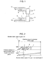
- Fig. 1 shows a structure of a detector of an absolute rotation angle and torque in accordance with an exemplary embodiment of the present invention.
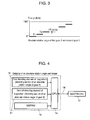
- Fig. 2 shows schematically how to find an absolute rotation angle.
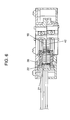
- Fig. 3 shows schematically how to find a torsion angle.
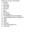
- Fig. 4 shows a block diagram of a detector in accordance with an exemplary embodiment of the present invention.
- Fig. 5 shows schematically how to correct an error.
- Fig. 6 shows a conventional detector of a rotation angle and torque.
- Fig. 1 shows a structure of a detector of an absolute rotation angle and torque in accordance with an exemplary embodiment of the present invention.
- a torsion-bar unit is formed of input shaft 2, torsion bar 5 and output shaft 4, and those elements are made of the same rigid body and placed concentrically.
- First gear 1 and second gear 3 are coupled to input shaft 2 and output shaft 4 respectively.
- First gear 1 engages with gear 6, and second gear 3 engages with gear 7.
- Gear 6 has first magnet 8 at its center, and gear 7 has second magnet 9 at its center.
- First magnet 8 and second magnet 9 are magnetized in one pole pair.
- Board 12 has first detecting element 10 of magnetism confronting first magnet 8, and board 13 has second detecting element 11 of magnetism confronting second magnet 9.
- First magnet 8 and first detecting element 10 form a first detecting section of an absolute rotation angle.
- Second magnet 9 and second detecting element 11 form a second detecting section of an absolute rotation angle.
- First gear 1 and second gear 3 have the same number of teeth "c”
- gear 6 has the number of teeth "a”
- gear 7 has the number of teeth "b" (a ⁇ b).
- rotation of input shaft 2 of the torsion-bar unit entails first gear 1 and gear 6 to rotate.
- First detecting element 10 detects magnetic field of first magnet 8, thereby calculating an absolute rotation angle of gear 6.
- Rotation of output shaft 4 entails second gear 3 and gear 7 to rotate.
- Second detecting element 11 detects magnetic field of second magnet 9, thereby calculating an absolute rotation angle of gear 7.
- Fig. 2 depicts a method of calculating an absolute rotation angle.
- the lateral axis represents absolute rotation angle “z" of first gear 1 and second gear 3.
- the upper column shows absolute rotation angles "x” and “y” of gear 6 and gear 7 respectively.
- the lower column shows a difference "x - y" between the absolute rotation angles of gear 6 and gear 7.
- the difference "x - y" draws a straight line and is uniquely related to absolute rotation angle "z", which can be thus calculated from the difference "x - y".
- difference T changes step by step as shown in Fig. 3 . If torsion bar 5 produces torsion ⁇ T, difference T changes by ⁇ T (c/a) with respect to the case where no torsion is produced, so that torsion angle ⁇ T can be calculated. This ⁇ T (c/a) is added to (x - y) shown in Fig. 2 , so that a detection accuracy of absolute rotation angle "z" can be improved. Torque can be calculated using torsion angle AT. When torsion angle ⁇ T exceeds a given allowance, the detector determines that an abnormality occurs and gives a warning.
- An absolute rotation angle and torque can be also detected in the condition of gear 6 and gear 7 having the same number of teeth, and first gear 1 has the number of teeth different from that of second gear 3.
- first detecting element 10 and second detecting element 11 are coupled to CPU 14, to which non-volatile memory EEPROM 15 is also coupled.
- CPU 14 is coupled to master CPU 17 via serial communication line 16 in order to output an absolute rotation angle and torque calculated by CPU 14.
- gear 6 and gear 7 are mounted to the torsion-bar unit, then an initial absolute rotation angle of gear 6 is calculated using a signal supplied from first detecting element 10, and that of gear 7 is calculated using a signal supplied from second detecting element 11.
- Those angles calculated are stored in EEPROM 15, and every time the power is turned on, the angles are read from EEPROM 15.
- a rotation angle starting from each one those initial absolute rotation angles is defined as respective absolute rotation angles of gear 6 and gear 7.
- absolute rotation angles (shown in solid lines) calculated by the detecting elements include errors due to a variety of factors with respect to respective correct absolute rotation angles (shown in broken lines), so that the following correction is provided: Gear 6 and gear 7 are mounted to the torsion-bar unit, then input shaft 2 is rotated with high accuracy, thereby obtaining a correction angle that is a difference between the correct absolute rotation angles and the absolute rotation angles of gear 6 and gear 7 calculated by the detecting elements.
- This correction angle is stored in EEPROM 15, and every time the power is turned on, this correction angle is read and added to the angles calculated by the detecting elements, so that an absolute rotation angle approximating to the correct one is obtainable.
- the detector of an absolute rotation angle and torque is suited to a power steering of cars.
Claims (7)
- Detektor für einen absoluten Drehwinkel und ein Drehmoment, wobei der Detektor umfasst:eine Torsionsstabeinheit, die eine Eingangswelle (2), eine Ausgangswelle (4) und einen Torsionsstab (5) enthält;ein erstes Zahnrad (1), das mit der Eingangswelle (2) gekoppelt ist;ein zweites Zahnrad (3), das mit der Ausgangswelle (4) gekoppelt ist;ein drittes Zahnrad (6), das mit dem ersten Zahnrad (1) in Eingriff ist;ein viertes Zahnrad (7), das mit dem zweiten Zahnrad (3) in Eingriff ist;einen ersten Erfassungsabschnitt (8, 10), der in einer Mitte des dritten Zahnrades (3) angeordnet ist, um einen absoluten Drehwinkel des dritten Zahnrades (6) zu erfassen;einen zweiten Erfassungsabschnitt (9, 11), der in einer Mitte des vierten Zahnrades (7) angeordnet ist, um einen absoluten Drehwinkel des vierten Zahnrades (7) zu erfassen; undeine CPU (14), die mit dem ersten und dem zweiten Erfassungsabschnitt (8, 9, 10, 11) gekoppelt ist,
dadurch gekennzeichnet, dassentweder das erste Zahnrad (1) und das zweite Zahnrad (3) eine identische Anzahl von Zähnen haben und das dritte Zahnrad (6) eine Anzahl von Zähnen hat, die sich von der des vierten Zahnrades (7) unterscheidet, oder das erste Zahnrad (1) eine Anzahl von Zähnen hat, die sich von der des zweiten Zahnrades (3) unterscheidet, und das dritte Zahnrad (6) und das vierte Zahnrad (7) eine identische Anzahl von Zähnen haben;die CPU (14) so eingerichtet ist, dass sie einen absoluten Drehwinkel der Torsionsstabeinheit aus einer Differenz zwischen jeweiligen absoluten Winkeln des dritten Zahnrades (6) und des vierten Zahnrades (7) berechnet,die CPU (14) des Weiteren so eingerichtet ist, dass sie ein Drehmoment aus einer Differenz zwischen einem absoluten Drehwinkel des dritten Zahnrades (6) und dem des vierten Zahnrades (7) multipliziert entweder mit dem Zähneverhältnis des dritten Zahnrades (6) und des vierten Zahnrades (7) oder dem Zähneverhältnis des ersten Zahnrades (1) und des zweiten Zahnrades (3) in Abhängigkeit davon berechnet, welches von 1 verschieden ist. - Detektor nach Anspruch 1, wobei der erste Erfassungsabschnitt (8, 10) einen ersten Magneten (8) und ein erstes Erfassungselement für Magnetismus (10) enthält, das dem ersten Magneten (8) gegenüberliegt.
- Detektor nach Anspruch 1 oder 2, wobei der zweite Erfassungsabschnitt (9, 11) einen zweiten Magneten (9) und ein zweites Erfassungselement für Magnetismus (11) enthält, das dem zweiten Magneten (9) gegenüberliegt.
- Detektor nach einem der Ansprüche 1 bis 3, wobei die CPU (14) des Weiteren so eingerichtet ist, dass sie den berechneten absoluten Drehwinkel auf Basis des Zähneverhältnisses des ersten und des dritten Zahnrades (6) multipliziert mit einem Torsionswinkel korrigiert, der aus dem berechneten Drehmoment hergeleitet wird.
- Detektor nach einem der Ansprüche 1 bis 4, der des Weiteren umfasst:einen nichtflüchtigen Speicher, in dem im Voraus jeweilige anfängliche absolute Drehwinkel des dritten Zahnrades (6) und des vierten Zahnrades (7) gespeichert werden, undwobei die CPU (14) des Weiteren so eingerichtet ist, dass sie die gespeicherten anfänglichen absoluten Drehwinkel beim Berechnen des absoluten Drehwinkels und des Drehmoments berücksichtigt.
- Detektor nach einem der Ansprüche 1 bis 5, der des Weiteren umfasst:einen nichtflüchtigen Speicher, in dem im Voraus eine Vielzahl von Korrekturwinkeln für das dritte (6) und das vierte Zahnrad (7) gespeichert werden, wobei die Korrekturwerte Differenzen zwischen tatsächlichen absoluten Drehwinkeln des dritten (6) unddes vierten Zahnrades (7) und durch den ersten bzw. den zweiten Erfassungsabschnitt (8, 9, 10, 11) erfassten absoluten Drehwinkeln anzeigen, undwobei die CPU (14) des Weiteren so eingerichtet ist, dass sie die gespeicherte Vielzahl von Korrekturwinkeln beim Berechnen des absoluten Drehwinkels und des Drehmoments berücksichtigt.
- Detektor nach einem der Ansprüche 1 bis 6, wobei die CPU (14) des Weiteren so eingerichtet ist, dass sie eine Abnormalitätswarnung ausgibt, wenn eine Differenz zwischen einem absoluten Drehwinkel des dritten Zahnrades (6) und dem des vierten Zahnrades (7) multipliziert entweder mit dem Zähneverhältnis des dritten Zahnrades (6) und des vierten Zahnrades (7) oder dem Zähneverhältnis des ersten Zahnrades (1) und des zweiten Zahnrades (3), in Abhängigkeit davon, welches sich von 1 unterscheidet, eine vorgegebene Toleranz überschreitet.
Applications Claiming Priority (3)
| Application Number | Priority Date | Filing Date | Title |
|---|---|---|---|
| JP2003309794A JP4474872B2 (ja) | 2003-09-02 | 2003-09-02 | 絶対回転角およびトルク検出装置 |
| JP2003309794 | 2003-09-02 | ||
| PCT/JP2004/012910 WO2005024369A1 (ja) | 2003-09-02 | 2004-08-31 | 絶対回転角度とトルクの検出装置 |
Publications (3)
| Publication Number | Publication Date |
|---|---|
| EP1536217A1 EP1536217A1 (de) | 2005-06-01 |
| EP1536217A4 EP1536217A4 (de) | 2006-09-20 |
| EP1536217B1 true EP1536217B1 (de) | 2008-08-20 |
Family
ID=34269622
Family Applications (1)
| Application Number | Title | Priority Date | Filing Date |
|---|---|---|---|
| EP04772859A Expired - Fee Related EP1536217B1 (de) | 2003-09-02 | 2004-08-31 | Gerät zur detektion von absolutem drehwinkel und drehmoment |
Country Status (6)
| Country | Link |
|---|---|
| US (1) | US7258027B2 (de) |
| EP (1) | EP1536217B1 (de) |
| JP (1) | JP4474872B2 (de) |
| CN (1) | CN100460842C (de) |
| DE (1) | DE602004015916D1 (de) |
| WO (1) | WO2005024369A1 (de) |
Cited By (1)
| Publication number | Priority date | Publication date | Assignee | Title |
|---|---|---|---|---|
| WO2017148534A1 (en) * | 2016-03-04 | 2017-09-08 | Thyssenkrupp Ag | Ripple minimization by proper as/ts magnet arrangement in electric power assisted steering apparatus |
Families Citing this family (28)
| Publication number | Priority date | Publication date | Assignee | Title |
|---|---|---|---|---|
| JP2007183121A (ja) * | 2006-01-05 | 2007-07-19 | Matsushita Electric Ind Co Ltd | 回転角およびトルク検出装置 |
| DE102006006359A1 (de) * | 2006-02-11 | 2007-08-16 | Leopold Kostal Gmbh & Co. Kg | Drehwinkelsensor sowie Verfahren zum Bestimmen der absoluten Winkelstellung eines über mehrere Runden drehbaren Körpers |
| JP4607033B2 (ja) * | 2006-02-28 | 2011-01-05 | 株式会社日本自動車部品総合研究所 | 回転角度検出装置 |
| JP2007256140A (ja) * | 2006-03-24 | 2007-10-04 | Matsushita Electric Ind Co Ltd | 回転角度・回転トルク検出装置 |
| JP4597907B2 (ja) * | 2006-05-16 | 2010-12-15 | 株式会社デンソー | 回転角検出装置 |
| US7562591B2 (en) * | 2006-06-26 | 2009-07-21 | KRS Technologies Co. | Steering angle sensor |
| JP4763540B2 (ja) * | 2006-07-21 | 2011-08-31 | 東洋電装株式会社 | 舵角センサ |
| JP5265362B2 (ja) * | 2006-07-25 | 2013-08-14 | エルジー イノテック カンパニー リミテッド | 操向角感知装置及び感知方法 |
| WO2008013372A1 (en) * | 2006-07-25 | 2008-01-31 | Lg Innotek Co., Ltd | Steering angle sensing apparatus and method thereof |
| FR2919385B1 (fr) * | 2007-07-24 | 2009-10-09 | Moving Magnet Tech Mmt | Capteur magnetique sans contact de position absolue multitour a arbre traversant |
| WO2010007068A1 (de) * | 2008-07-14 | 2010-01-21 | Continental Teves Ag & Co. Ohg | Drehmomentsensoranordnung mit drehwinkel-index-erfassung |
| DE102009022712A1 (de) * | 2009-05-26 | 2010-12-02 | Bourns, Inc., Riverside | Torsionswinkelsensor |
| WO2011002346A1 (en) * | 2009-06-29 | 2011-01-06 | Volvo Lastvagnar Ab | A method and a system for assisting a driver of a vehicle during operation |
| CN102155932B (zh) * | 2010-07-01 | 2012-06-27 | 长春设备工艺研究所 | 用于扭力轴扭转试验的双编码器角度检测系统 |
| JP2012173268A (ja) * | 2011-02-24 | 2012-09-10 | Honda Motor Co Ltd | 角度検出器及び電動パワーステアリング装置 |
| DE102011106339B4 (de) * | 2011-03-04 | 2012-12-06 | Auma Riester Gmbh & Co. Kg | Messvorrichtung zur Erfassung des Absolutdrehwinkels eines rotierenden Messobjekts |
| DE102011052043B4 (de) | 2011-07-21 | 2022-06-09 | Bourns, Inc. | Drehwinkel- und Torsionswinkelsensor |
| CN102506698B (zh) * | 2011-11-04 | 2014-03-12 | 合肥工业大学 | 一种非接触式转角转矩传感器 |
| DE102012022869A1 (de) * | 2012-11-21 | 2014-05-22 | Volkswagen Aktiengesellschaft | Lenkwinkelsensor und Vorrichtung zur kombinierten Erfassung von einem Winkel und einem Drehmoment |
| CN103085876A (zh) * | 2013-01-10 | 2013-05-08 | 青岛科技大学 | 销轴铰接车辆转向角度检测装置 |
| CN103112496A (zh) * | 2013-01-10 | 2013-05-22 | 青岛科技大学 | 销轴铰接车辆转向角度检测装置 |
| DE102013001829B4 (de) | 2013-02-04 | 2014-08-21 | Bourns, Inc. | Drehwinkel- und Torsionswinkelsensor |
| JP6083428B2 (ja) * | 2014-12-16 | 2017-02-22 | トヨタ自動車株式会社 | 車両の電動パワーステアリング装置 |
| CN106541985A (zh) * | 2016-10-13 | 2017-03-29 | 北京联合大学 | 用于无人驾驶电动车辆的自动驾驶控制器及其车辆 |
| US11022463B2 (en) * | 2016-12-27 | 2021-06-01 | Kabushiki Kaisha Tokai Rika Denki Seisakusho | Position sensor and shift lever device |
| DE102017116764A1 (de) | 2017-07-25 | 2019-01-31 | Danfoss Power Solutions Aps | Lenkhandrad-Winkelsensor und Verfahren zur Fehlererfassunq eines Lenkhandrad-Winkelsensors |
| JP7000263B2 (ja) * | 2018-06-20 | 2022-01-19 | 株式会社東海理化電機製作所 | 初期設定方法及び初期設定装置 |
| WO2020133471A1 (zh) * | 2018-12-29 | 2020-07-02 | 深圳市优必选科技有限公司 | 转动角度的检测方法及装置 |
Citations (4)
| Publication number | Priority date | Publication date | Assignee | Title |
|---|---|---|---|---|
| EP0338559A2 (de) * | 1988-04-22 | 1989-10-25 | Hitachi, Ltd. | Gerät zur Drehmomentdetektion mit Fehlersignal |
| DE10060287A1 (de) * | 1999-12-06 | 2001-06-07 | Bosch Gmbh Robert | Vorrichtung zur Messung des Winkels und/oder der Winkelgeschwindigkeit eines drehbaren Körpers und/oder des auf ihn wirkenden Drehmoments |
| US6578437B1 (en) * | 1998-08-07 | 2003-06-17 | Robert Bosch Gmbh | Sensor array for detecting rotation angle and/or torque |
| US20030155627A1 (en) * | 2002-02-15 | 2003-08-21 | Shigetoshi Fukaya | Adjustment-circuit embedded semiconductor sensor and torsion bar type torque sensor system |
Family Cites Families (11)
| Publication number | Priority date | Publication date | Assignee | Title |
|---|---|---|---|---|
| JPH05231968A (ja) * | 1992-02-24 | 1993-09-07 | Ono Sokki Co Ltd | トルク検出装置 |
| DE19506938A1 (de) | 1995-02-28 | 1996-08-29 | Bosch Gmbh Robert | Verfahren und Vorrichtung zur Winkelmessung bei einem drehbaren Körper |
| JPH10142082A (ja) * | 1996-11-07 | 1998-05-29 | Toyoda Mach Works Ltd | トルクセンサ |
| DE19834322B4 (de) * | 1998-07-30 | 2015-06-11 | Robert Bosch Gmbh | Verfahren und Vorrichtung zur Ermittlung des auf eine Welle wirkenden Drehmoments |
| US6935193B2 (en) | 1999-12-06 | 2005-08-30 | Robert Bosch Gmbh | Device for measuring the angle and/or the angular velocity of a rotatable body and/or the torque acting upon said body |
| JP2003270062A (ja) * | 2002-03-13 | 2003-09-25 | Koyo Seiko Co Ltd | 回転角度検出装置、トルク検出装置及び舵取装置 |
| JP2004020370A (ja) * | 2002-06-17 | 2004-01-22 | Matsushita Electric Ind Co Ltd | トルク検出装置 |
| JP2004144716A (ja) * | 2002-10-28 | 2004-05-20 | Koyo Seiko Co Ltd | 回転角検出装置及びトルク検出装置 |
| JP3938902B2 (ja) * | 2002-11-27 | 2007-06-27 | 株式会社ジェイテクト | 角度検出装置及びそれを備えたトルクセンサ |
| JP4120425B2 (ja) * | 2003-02-28 | 2008-07-16 | 株式会社ジェイテクト | 回転角度検出装置及びトルク検出装置 |
| JP2005077305A (ja) * | 2003-09-02 | 2005-03-24 | Matsushita Electric Ind Co Ltd | 回転角度およびトルク検出装置 |
-
2003
- 2003-09-02 JP JP2003309794A patent/JP4474872B2/ja not_active Expired - Fee Related
-
2004
- 2004-08-31 US US10/528,586 patent/US7258027B2/en not_active Expired - Fee Related
- 2004-08-31 WO PCT/JP2004/012910 patent/WO2005024369A1/ja active IP Right Grant
- 2004-08-31 DE DE602004015916T patent/DE602004015916D1/de active Active
- 2004-08-31 CN CNB2004800009509A patent/CN100460842C/zh not_active Expired - Fee Related
- 2004-08-31 EP EP04772859A patent/EP1536217B1/de not_active Expired - Fee Related
Patent Citations (4)
| Publication number | Priority date | Publication date | Assignee | Title |
|---|---|---|---|---|
| EP0338559A2 (de) * | 1988-04-22 | 1989-10-25 | Hitachi, Ltd. | Gerät zur Drehmomentdetektion mit Fehlersignal |
| US6578437B1 (en) * | 1998-08-07 | 2003-06-17 | Robert Bosch Gmbh | Sensor array for detecting rotation angle and/or torque |
| DE10060287A1 (de) * | 1999-12-06 | 2001-06-07 | Bosch Gmbh Robert | Vorrichtung zur Messung des Winkels und/oder der Winkelgeschwindigkeit eines drehbaren Körpers und/oder des auf ihn wirkenden Drehmoments |
| US20030155627A1 (en) * | 2002-02-15 | 2003-08-21 | Shigetoshi Fukaya | Adjustment-circuit embedded semiconductor sensor and torsion bar type torque sensor system |
Cited By (2)
| Publication number | Priority date | Publication date | Assignee | Title |
|---|---|---|---|---|
| WO2017148534A1 (en) * | 2016-03-04 | 2017-09-08 | Thyssenkrupp Ag | Ripple minimization by proper as/ts magnet arrangement in electric power assisted steering apparatus |
| US10800452B2 (en) | 2016-03-04 | 2020-10-13 | Thyssenkrupp Ag | Ripple minimization by proper AS/TS magnet arrangement in electric power assisted steering apparatus |
Also Published As
| Publication number | Publication date |
|---|---|
| US7258027B2 (en) | 2007-08-21 |
| JP2005077304A (ja) | 2005-03-24 |
| DE602004015916D1 (de) | 2008-10-02 |
| CN1701221A (zh) | 2005-11-23 |
| EP1536217A1 (de) | 2005-06-01 |
| JP4474872B2 (ja) | 2010-06-09 |
| EP1536217A4 (de) | 2006-09-20 |
| WO2005024369A1 (ja) | 2005-03-17 |
| US20060042403A1 (en) | 2006-03-02 |
| CN100460842C (zh) | 2009-02-11 |
Similar Documents
| Publication | Publication Date | Title |
|---|---|---|
| EP1536217B1 (de) | Gerät zur detektion von absolutem drehwinkel und drehmoment | |
| EP2491335B1 (de) | Sensor mit mehrfachdrehung | |
| US6507188B1 (en) | Device and method for detecting the relative position of a rotatable body | |
| US6519549B1 (en) | Method and device for determining absolute angular position of a rotating body | |
| EP2477003B1 (de) | Vorrichtung zur Drehwinkelerfassung | |
| WO2006085569A1 (ja) | 回転角度検出装置及び回転角度補正方法 | |
| JP2006220530A (ja) | 絶対回転角度検出装置 | |
| EP2682717A1 (de) | Positionsmesseinrichtung | |
| US20090320613A1 (en) | Rotation angle and torque detection device | |
| CN103201596A (zh) | 适于通过多次转动提供输入部件的角位置的指示的设备 | |
| KR20060073960A (ko) | 조향각 센서 | |
| EP1845352A1 (de) | Verfahren zur drehwinkel- und drehmomenterfassung | |
| US8810239B2 (en) | Angle sensor | |
| US20050075828A1 (en) | Rotation angle sensor | |
| EP1544580B1 (de) | Winkelgeber | |
| US20050022613A1 (en) | Angle sensor | |
| KR20150082920A (ko) | 앵글 센서 및 이를 포함하는 토크 앵글 센서 | |
| JP2006275558A (ja) | 絶対回転角検出機能付きトルク検出装置 | |
| US7370540B2 (en) | Rotation angle sensor, in particular for an electrical steering system of an industrial truck | |
| JPH0353114A (ja) | 位置検出装置 | |
| WO2007094196A1 (ja) | トルク検出装置および回転角度検出装置 | |
| KR100827818B1 (ko) | 축회전체의 회전각도 측정방법 | |
| EP2058628A2 (de) | Verfahren und Vorrichtung zur Positionsüberwachung eines Drehbolzens | |
| KR20130128549A (ko) | 앵글센서 | |
| JP2005201712A (ja) | 回転角度およびトルク検出装置 |
Legal Events
| Date | Code | Title | Description |
|---|---|---|---|
| PUAI | Public reference made under article 153(3) epc to a published international application that has entered the european phase |
Free format text: ORIGINAL CODE: 0009012 |
|
| 17P | Request for examination filed |
Effective date: 20050318 |
|
| AK | Designated contracting states |
Kind code of ref document: A1 Designated state(s): AT BE BG CH CY CZ DE DK EE ES FI FR GB GR HU IE IT LI LU MC NL PL PT RO SE SI SK TR |
|
| AX | Request for extension of the european patent |
Extension state: AL HR LT LV MK |
|
| RIN1 | Information on inventor provided before grant (corrected) |
Inventor name: OIKE, KOJI Inventor name: USHIHARA, MASAHARUMATSUSHITA ELECTRIC INDUSTRIAL Inventor name: UEHIRA, KIYOTAKA |
|
| A4 | Supplementary search report drawn up and despatched |
Effective date: 20060823 |
|
| DAX | Request for extension of the european patent (deleted) | ||
| RBV | Designated contracting states (corrected) |
Designated state(s): DE FR GB |
|
| 17Q | First examination report despatched |
Effective date: 20061207 |
|
| GRAP | Despatch of communication of intention to grant a patent |
Free format text: ORIGINAL CODE: EPIDOSNIGR1 |
|
| GRAS | Grant fee paid |
Free format text: ORIGINAL CODE: EPIDOSNIGR3 |
|
| GRAA | (expected) grant |
Free format text: ORIGINAL CODE: 0009210 |
|
| AK | Designated contracting states |
Kind code of ref document: B1 Designated state(s): DE FR GB |
|
| REG | Reference to a national code |
Ref country code: GB Ref legal event code: FG4D |
|
| REF | Corresponds to: |
Ref document number: 602004015916 Country of ref document: DE Date of ref document: 20081002 Kind code of ref document: P |
|
| RAP2 | Party data changed (patent owner data changed or rights of a patent transferred) |
Owner name: PANASONIC CORPORATION |
|
| PLBE | No opposition filed within time limit |
Free format text: ORIGINAL CODE: 0009261 |
|
| STAA | Information on the status of an ep patent application or granted ep patent |
Free format text: STATUS: NO OPPOSITION FILED WITHIN TIME LIMIT |
|
| 26N | No opposition filed |
Effective date: 20090525 |
|
| PGFP | Annual fee paid to national office [announced via postgrant information from national office to epo] |
Ref country code: FR Payment date: 20100824 Year of fee payment: 7 |
|
| PGFP | Annual fee paid to national office [announced via postgrant information from national office to epo] |
Ref country code: GB Payment date: 20100825 Year of fee payment: 7 |
|
| GBPC | Gb: european patent ceased through non-payment of renewal fee |
Effective date: 20110831 |
|
| REG | Reference to a national code |
Ref country code: FR Ref legal event code: ST Effective date: 20120430 |
|
| PG25 | Lapsed in a contracting state [announced via postgrant information from national office to epo] |
Ref country code: FR Free format text: LAPSE BECAUSE OF NON-PAYMENT OF DUE FEES Effective date: 20110831 Ref country code: GB Free format text: LAPSE BECAUSE OF NON-PAYMENT OF DUE FEES Effective date: 20110831 |
|
| PGFP | Annual fee paid to national office [announced via postgrant information from national office to epo] |
Ref country code: DE Payment date: 20150825 Year of fee payment: 12 |
|
| REG | Reference to a national code |
Ref country code: DE Ref legal event code: R119 Ref document number: 602004015916 Country of ref document: DE |
|
| PG25 | Lapsed in a contracting state [announced via postgrant information from national office to epo] |
Ref country code: DE Free format text: LAPSE BECAUSE OF NON-PAYMENT OF DUE FEES Effective date: 20170301 |