EP1536094A2 - Windlast-Stützvorrichtung sowie damit versehener Rollabschluss - Google Patents
Windlast-Stützvorrichtung sowie damit versehener Rollabschluss Download PDFInfo
- Publication number
- EP1536094A2 EP1536094A2 EP04026102A EP04026102A EP1536094A2 EP 1536094 A2 EP1536094 A2 EP 1536094A2 EP 04026102 A EP04026102 A EP 04026102A EP 04026102 A EP04026102 A EP 04026102A EP 1536094 A2 EP1536094 A2 EP 1536094A2
- Authority
- EP
- European Patent Office
- Prior art keywords
- support arm
- roll
- wing
- arm
- wind load
- Prior art date
- Legal status (The legal status is an assumption and is not a legal conclusion. Google has not performed a legal analysis and makes no representation as to the accuracy of the status listed.)
- Withdrawn
Links
Images


Classifications
-
- E—FIXED CONSTRUCTIONS
- E06—DOORS, WINDOWS, SHUTTERS, OR ROLLER BLINDS IN GENERAL; LADDERS
- E06B—FIXED OR MOVABLE CLOSURES FOR OPENINGS IN BUILDINGS, VEHICLES, FENCES OR LIKE ENCLOSURES IN GENERAL, e.g. DOORS, WINDOWS, BLINDS, GATES
- E06B9/00—Screening or protective devices for wall or similar openings, with or without operating or securing mechanisms; Closures of similar construction
- E06B9/56—Operating, guiding or securing devices or arrangements for roll-type closures; Spring drums; Tape drums; Counterweighting arrangements therefor
- E06B9/58—Guiding devices
-
- E—FIXED CONSTRUCTIONS
- E06—DOORS, WINDOWS, SHUTTERS, OR ROLLER BLINDS IN GENERAL; LADDERS
- E06B—FIXED OR MOVABLE CLOSURES FOR OPENINGS IN BUILDINGS, VEHICLES, FENCES OR LIKE ENCLOSURES IN GENERAL, e.g. DOORS, WINDOWS, BLINDS, GATES
- E06B9/00—Screening or protective devices for wall or similar openings, with or without operating or securing mechanisms; Closures of similar construction
- E06B9/02—Shutters, movable grilles, or other safety closing devices, e.g. against burglary
- E06B9/08—Roll-type closures
- E06B9/11—Roller shutters
- E06B9/17—Parts or details of roller shutters, e.g. suspension devices, shutter boxes, wicket doors, ventilation openings
- E06B9/17076—Sealing or antirattling arrangements
Definitions
- the invention relates to a wind load support device for a roll termination and a provided roll closure.
- Roll ends generally have a windable on a winding shaft wings successively hinged rods or one by one or several cross bars reinforced flexible material.
- Rolling shutters in the form of roll-up doors can close quite large entrance openings. Wind loads can be the closed wing act on such that a central area is far out of the Closing plane moves. This can lead to malfunction or damage.
- the wind load support device has a kind of storm bar, which automatically with the Wings of the Rollab gleiches is moved and one of the lateral guides removed arranged area thereof, in particular a central area, against Wind loads or the like stresses - are also conceivable mechanical stresses by persons, objects or vehicles.
- the wind load supporting device has a wall fastening device, with which they at the Opening boundary, in particular attachable to a fall.
- a support arm, against the area to be supported can be supported when acted upon, is with a End hinged to this wall mounting device.
- the support arm is between one disengaged position in which it fulfills a supporting function and from the opening boundary extends into the region of the opening essentially parallel to the closing plane, and a retracted from the region of the opening position movable.
- There is a Carrier which articulates the support arm on the wing and so the support arm Moving between these positions when moving the wing.
- the wind load supporting device is now still with its own retraction device Mistake.
- the retraction device helps the wing in doing so, the support arm to withdraw from its disengaged position to its withdrawn position.
- One the wing moving drive must be so when pulling up the wing during the opening movement do not even move the support arm. This will be mechanical Demands on the wing and the entire drive mechanism reduced.
- the retraction device can be constructed very differently, depending on how the Movement mechanism of the support arm is executed. In essence, the withdrawal device could also have a small traction drive. Preferably, the withdrawal device but simply formed by a pretensioner that holds the support arm in its withdrawn position biases.
- the design of the retractor or pretensioner may vary be. It can only be provided a support of the wing; it is also conceivable that the pretension or retraction force is greater than that for the pure retraction of the Low-support force required; then this bias or retraction device still helps the roller door drive when opening the gate.
- the support arm can be hinged or pivoted on the fastening device or the Wing hinged.
- the corresponding hinge opposite end of the Support arm is then preferred in a preferably transverse to the opening movement held the wing extending rectilinear guide.
- this guide through a groove or the like on the end profile of the wing, in which engages a pin of the driving device formed.
- the support arm may alternatively or preferably in addition to this pivotal movement also be designed as a telescopic arm to the movement between the end positions to enable.
- the telescopic design is especially in a joint or the like successful articulation advantageous for the support arm in narrower and / or higher roll ends in the retracted position not laterally over the wing also available.
- a telescopic guide Especially with a telescopic guide is the retractor or pretensioner advantageous.
- a longer telescopic movement with appropriate larger telescopic arm weight and / or greater resistance in the telescopic movement be handled without burdening the wing or its drive more.
- the free end of the support arm is preferably opposite to the attachment device fixed boundary area of the opening, preferably on the ground secured by a safety device.
- This can act as a pin or similar engaging device for engaging in a recess on an abutment, for example formed by a round hole in the bottom, be formed.
- the fastening device itself preferably has a hollow area, for example formed by a bracket which can be fastened to the lintel above the winding shaft is and the winding shaft completely embraces such that the entire rolling armor or the like Wing undisturbed on the winding shaft is wound up.
- a roll-up door is provided with a bracket which is on the lintel area is fastened above the winding shaft and the winding shaft in the manner described above completely encompassing.
- the console has a boom, the distance, for example, 10 - 30 cm, inside guided by a guide for the wing. At this boom is the support arm or support bar mounted on a hinge.
- the gate When pulling up puts down the end profile or any other the closing edge of the Rollab gleiches exhibiting Part (eg end bar) on the beam or support arm.
- the gate then heaves in addition next to the rolling armor or similar wing still the support arm high. This is going through supports the withdrawal device. With a correspondingly strong pulling force of the retracting device This also pulls up the rolling armor and not vice versa.
- the pivoting movement may be limited by a stop mechanism. It is also preferably provided a telescopic mechanism.
- the free end of the support arm is formed by the tip of a rod, which engages in a receptacle. The rod especially dives into a round hole.
- one end of the support arm is on the closing edge region of the wing pivoted about an axis, but not displaced articulated.
- the other end is hinged to the fastening device. This is done either such that even this end is only pivotally mounted and not displaceable, in In this case, the pivoting movement of the support arm alone by the shortening allows a correspondingly formed telescopic device.
- the fastening device facing the end is in a longitudinal guide on the fastening device slidably guided; then the telescopic mechanism can be less be elaborately designed, but the wall mounting device is more complex, formed for example by two or more consoles.
- Wind load support devices with a simple wall attachment device are in particular suitable for roll closures of openings that are significantly wider than high.
- a telescopic arm is provided as a support. Because the support arm As far as possible in the middle attack, to support wind loads, but is also here limits the height of the roll completion. Any extensions of the telescopic arm would mean too high costs and a (too) filigree education.
- the invention provides that the wall fastening means the end of the Wind load supporting device at least with a direction perpendicular to the direction of closing movement and parallel to the opening plane extending direction component movable on the Wall stores.
- the roller door 10 shown in Fig. 1 has a guided along side guides 12 and windable on a winding shaft 14 wings in the form of a rolling shell 16.
- the winding shaft 14 is mounted on side brackets 18, 19 in the region of the camber 20.
- a drive 22 is used for driven opening and shooting of the rolling arm 16 by driving a rotational movement of the winding shaft fourteenth
- the roller shutter 10 is further provided with a total of 24 designated wind load support.
- the wind last support 24 has a fastening device in the form of a bracket 26, a telescopic arm 27 as part of a support arm 29, a driving device 28 and a Securing device 30.
- the bracket 26 engages at a distance from the bracket Winding shaft 14 around.
- the bracket 26 is provided with a boom 32.
- On the boom 32 is the upper end 34 of the telescopic arm 27 at a preferably one-dimensional Hinge joint 36 about a perpendicular to the closing plane of the rolling armor 16 standing pivot axis pivotally mounted.
- the lower end 38 of the telescopic arm 27 has the entrainment device 28 and the securing device 30 on.
- the securing device 30 is designed as an engagement device and has a projection in the form of a pin 40, which in a formed by a hole 42 in the bottom counter bearing can intervene.
- the entrainment device 28 has an attached at the lower end 38 engaging element in Shape of a pin-like projection 44, which in a transverse to the opening direction of the rolling arm 16 engages on the end profile 46 formed groove 48.
- the not shown in detail groove 48 may be made wider inside, so that a head-like end 64 (eg, Fig. 4) - formed as a roll - of the projection 44th slidably guided guided guided in this groove 48 guided.
- a head-like end 64 eg, Fig. 4
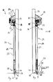
- FIGS. 4 and 5 show the retracted position and FIG. 6 and Fig. 7 show the exploded position.
- Figs. 8 to 14 show the telescopic arm 27 in different views in detail.
- the telescopic arm 27 is formed by an outer tube 50 and an inner tube 52, which are retractable into each other.
- the free end of the outer tube 50 carries the telescopic arm side Part of the joint 36.
- a traction means in shape attached to a chain 54 or the like which is guided concentrically through the tubes 50-52 is.
- a tension spring 56 is attached, the other end is fastened inside the free end region of the inner tube 52.
- One side of the inner tube 52 is provided with two slide strips 62 which are between them leave a groove 71 open.
- the other sides are provided with sliding plates 76.
- the sliding strips 62 and sliding plates 76 are made of a material having a relatively low frictional resistance compared to the pipe materials, for example made of plastic in training the Tubes of steel or aluminum.
- the slide strips 62 and the groove 71 are part of a pull-out 80, which limits a pulling apart of the two telescopic parts 50, 52.
- the sliding strips 62 are not arranged continuously on the inner tube 52, they rather end on a further sliding plate 76, the end face region 78 of the groove 71st limited, thus forming a stop.
- Into the groove 71 is a preferably removable Lead introduced.
- the inner structure of the telescopic arm 27 is best seen in FIGS. 11-14.
- the lower end 38 with the pin 40 has an end tube 84 which by means of screws 86 is attached to the inner tube 52.
- the slide strips 62 and the sliding plates 76 create Space between the two tubes 50, 52, in which corresponding screw heads space Find.
- the position of the end piece to the inner tube can in non-illustrated embodiments by selectively securing the screw connections 86 in slots or a series of threaded holes adjustable to the length of the Telescope arm 27 to adapt to local conditions.
- a bolt 88 is guided, on which the projection 44 forming Roller 90 is rotatably mounted.
- the bolt 88 also serves to attach the Tension spring 56.
- the tension spring 56 biases as biasing means the tubes 52, 50 in their pushed together Situation before.
- the tension spring 56 and the chain 54 together form a retraction device, the telescopic arm 27 from that indicated in Fig. 1 by the reference numeral 66 withdrawing disengaged position.
- a fully retracted position, which occupies the support arm 27 when the rolling arm 16 is fully open, is in Fig. 1st designated by the reference numeral 70.
- Fig. 1 are for illustration purposes both Positions 66, 70 drawn, although only a support arm 27 in this embodiment is available.
- a tension adjuster 92 (see FIG. 13) is provided. This is arranged here on the joint-side end of the telescopic arm 27 and designed so that it is accessible from the outside. This is in the example the chain 54 (or other traction means) adjustable in length. In the concrete example is the chain 54 at the hinged end of the outer tube 50 through a through hole passed through in the end plate and on a bevel mandrel 94 through a chain link can be passed, determined.
- the tubes 50, 52 are, as shown in FIG. 6 and FIG. 11, rotationally fixed to each other guided.
- the groove projection guide 72 is provided.
- the cross-sectional profile of the tubes is preferably non-circular, for example rectangular. see Fig. 11.
- the wind load support 24 is in the disengaged Position 66.
- the pin 40 of the securing device 30 engages in the hole 42 on the ground and thus secures the lower end 38 of the telescopic arm 27.
- the upper end 34 is on held the boom 32.
- the support arm is located 29 along its entire length relatively close to the rolling arm 16. From Fig. 1 it can be seen in that the telescopic arm 27 is arranged at a middle region of the rolling-stock tank. Especially this middle area becomes particularly in wind load or the like loads deflected after the edge portions of the rolling arm 16 in the lateral guides 12 are guided.
- the middle area of the rolling arm bent inwards and is supported on the telescopic arm 27.
- the middle area of the final profile 46 is from the outset on the projection 44 and the pin 40 with secured short path to the hole 42. So here is also a deflection of the rolling armor avoided to the outside with appropriate differential pressure.
- the lower end 38 of the Teleskoparmes is biased by the tension spring 56 in the upward direction. It will but about the engagement of the driving device 28 on the end profile 46 in place and Place held.
- the end profile 46 is held down by its own weight.
- roller shutter to be supported has a width W of at least 1.2 times its height H exhibit.
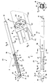
- the further embodiment shown in FIGS. 15 to 17 is against it also designed for narrower and / or higher roller doors.
- the generally designated 10 roller door of the further embodiment has a rolling armor 16 and a generally designated 24 wind load support.
- the wind load support 24 has a wall mounting device 100 and a thus on the upper lintel 20th and side-mounted support arm 29.
- the support arm 29 may as in the preceding Embodiment described be designed as a telescopic arm 27. With the lower end is the support arm 29 near the closing edge of the rolling arm 16 at the lower blade with a driving device 28 in the sliding guide (not closer here shown), as stated above.
- the wall mounting device 100 the upper end 102 of the support arm 29 at attached to the lintel, has a sliding guide 104 in which the upper end 102 of the Support arm 29 in an analogous manner, as the lower end of the support arm 29 on the rolling armor 16 is fixed, in a horizontal direction P parallel to the opening plane displaceable is guided.
- the wall fastening device 100 is connected by means of a around the winding shaft 14 around Extender 32 on the lintel 20 above the through the roll closure 10 to be closed Opening attached.
- the boom engages in the embodiment of a Rod 120, which is arranged approximately horizontally and the sliding guide 104 forms or carries.
- the rod 120 is on one side across the width of the rolling stock and optionally guided over the lateral guide rails out and with a Sidewall bracket 122 at one of the opening to be closed bounding sidewall attached.
- the one end of the arm 106 is around the first axis 108 pivotally mounted.
- the rolling armor width is shown in Fig. 1 with the Reference symbol W denotes.
- the dotted line 124 denotes the center of the Rollpanzererstreckung and the center of the opening to be closed.
- the first axis 108 is located approximately on this center line 124th
- the closed position 116 of the wind load support 24 is fully closed Gate shown with solid lines.
- the opening position 111 of the wind load support 24 at fully open gate and an intermediate position 112 are dashed Lines shown. As you can see, it shifts when closing of the roll-up door 10, the upper end 102 of the support arm 29 in the sliding guide 104th from the outside to the center of the roll-up door 10 back.
- the displacement guide 104 is located in the embodiment shown in FIGS. 15 to 17 on the inside of the rod 120 directed towards the rolling arm can be quite different.
- the rod 120 itself could serve as a rail, which is of a corresponding Carriage at the upper end of the support arm 29 is included.
- the rod designed as a slotted hollow profile, for example as a C-shaped profile be in whose interior one connected to the upper end 102 of the support arm Scroll or the like is running.
Landscapes
- Engineering & Computer Science (AREA)
- Structural Engineering (AREA)
- Architecture (AREA)
- Civil Engineering (AREA)
- Operating, Guiding And Securing Of Roll- Type Closing Members (AREA)
Abstract
- einer Wandbefestigungseinrichtung (26) zum ortsfesten Befestigen eines Endbereichs der Windlast-Stützvorrichtung (24),
- einem Stützarm (27), der einenends an der Befestigungseinrichtung (26) angelenkt ist, in einer ausgerückten Position (66) zum Stützen eines mittleren Bereichs eines Flügels (16) des Rollabschlusses (10) gegen Windbeaufschlagung oder dergleichen geeignet ist und in einer zurückgezogenen Position (70) die Öffnung im wesentlichen freigibt, und
- einer Mitnahmeeinrichtung (28), die den Stützarm (27) bei Bewegung des Flügels (16) zwischen der ausgerückten (66) und der zurückgezogenen Position (70) oder umgekehrt mitbewegt.
Description
- Fig. 1
- eine Rückansicht vom Inneren eines zu verschließenden Gebäude aus gesehen auf einen mit einer Windlast-Stützvorrichtung versehenen Rollabschluss in Form eines Rolltores gemäß einer ersten Ausführungsform;
- Fig. 2
- eine Seitenansicht auf das Rolltor von Fig. 1 von rechts in Fig. 1 gesehen;
- Fig. 3
- eine Seitenansicht auf das Rolltor von links von Fig. 1 gesehen;
- Fig. 4
- eine Seitenansicht auf einen als Teleskoparm ausgeführten Stützarm der Windlast-Stützvorrichtung des in Fig. 1 gezeigten Rolltores in eingefahrenem Zustand;
- Fig. 5
- den eingefahrenen Stützarm in einer Schnittdarstellung entlang der Linie A-A von Fig. 4;
- Fig. 6
- eine Ansicht wie in Fig. 4 auf den Stützarm im ausgefahrenen Zustand;
- Fig. 7
- eine Schnittdarstellung vergleichbar Fig. 5 des Stützarmes im ausgefahrenen Zustand entlang der Linie A - A von Fig. 6;
- Fig. 8
- eine perspektivische Ansicht des Stützarmes im ausgefahrenen Zustand;
- Fig. 9
- eine vergrößerte Ansicht des Details X von Fig. 8;
- Fig.10
- eine teilweise weggebrochene Seitenansicht des Stützarmes;
- Fig. 11
- einen Schnitt durch den Stützarm entlang der Linie B - B von Fig. 10;
- Fig. 12
- eine weitere Seitenansicht des Stützarmes vergleichbar mit der Fig. 10 jedoch in größerem Maßstab;
- Fig. 13
- einen Schnitt durch den Stützarm entlang der Linie AA - AA von Fig. 12;
- Fig. 14
- einen Schnitt durch den Stützarm entlang der Linie BB - BB von Fig. 13;
- Fig. 15
- eine schematische Rückansicht auf eine weitere Ausführungsform eines Rollabschlusses in Form eines Rolltores mit einer verschiebbaren Windlaststützvorrichtung;
- Fig. 16
- eine Seitenansicht auf den Rollabschluss gemäß der weiteren Ausführungsform von rechts in Fig. 15 gesehen; und
- Fig. 17
- einen Schnitt entlang der Linie A - A von Fig. 15.
Claims (23)
- Windlast-Stützvorrichtung (24) für einen Rollabschluss (10), mit:einer Wandbefestigungseinrichtung (26, 100) zum Befestigen eines Endbereichs (102) der Windlast-Stützvorrichtung (24) an einer eine durch den Rollabschluss (10) zu verschließende Öffnung berandenden Wandung (20),einem Stützarm (29, 27), der einenends an der Befestigungseinrichtung (26, 100) angelenkt ist, in einer ausgerückten Position (66, 116) zum Stützen eines mittleren Bereichs eines Flügels (16) des Rollabschlusses (10) gegen Windbeaufschlagung oder dergleichen geeignet ist und in einer zurückgezogenen Position (70, 111) die Öffnung im wesentlichen freigibt, undeiner Mitnahmeeinrichtung (28), die an dem Flügel (16) angreifen kann, um den Stützarm (29, 27) bei Bewegung des Flügels (16) zwischen der ausgerückten (66, 116) und der zurückgezogenen Position (70, 111) oder umgekehrt mitzubewegen.
- Vorrichtung nach Anspruch 1,
gekennzeichnet durcheine eigene Zurückzieheinrichtung (54, 56) zum Zurückziehen des Stützarmes (29, 27) in Richtung der zurückgezogenen Position (70, 111). - Vorrichtung nach Anspruch 2,
dadurch gekennzeichnet, dass die Zurückzieheinrichtung (54, 56) eine Vorspanneinrichtung (56) aufweist, die den Stützarm (29, 27) in Richtung auf die zurückgezogene Position (70, 111) vorspannt. - Vorrichtung nach einem der voranstehenden Ansprüche,
dadurch gekennzeichnet, dass der Stützarm (29) ein Teleskoparm (27) ist oder einen solchen aufweist. - Vorrichtung nach Anspruch 3 und 4,
dadurch gekennzeichnet, dass die Vorspanneinrichtung eine Zugfeder (56) hat, die den Teleskoparm (27) in eine zusammengeschobene Stellung vorspannt. - Vorrichtung nach einem der voranstehenden Ansprüche,
dadurch gekennzeichnet, dass der Teleskoparm (27) wenigstens zwei ineinandergreifende relativ zueinander längsverschiebliche Rohrstangen (50, 52) aufweist, in deren Inneren die Zurückzieheinrichtung, Vorspanneinrichtung oder Zugfeder (56) angeordnet ist. - Vorrichtung nach einem der voranstehenden Ansprüche,
dadurch gekennzeichnet, dass der Teleskoparm (27) relativ zueinander verschiebbare Teleskopteile (50, 52) aufweist, deren Relativbewegung durch eine Ausziehsicherung (80) auf ein maximales Maß begrenzt ist. - Vorrichtung nach Anspruch 7,
dadurch gekennzeichnet, dass die Ausziehsicherung lösbar ist zum Entfernen der beiden Teleskopteile (50, 52) für Reparatur, Wartung oder zum einfachen Montieren der beiden Teleskopteile (50, 52) aneinander. - Vorrichtung nach einem der voranstehenden Ansprüche,
dadurch gekennzeichnet, dass die Teleskopteile (50, 52) unter Zwischenlagerung einer Gleiteinrichtung (62, 76) aufeinander gleitend und, vorzugsweise durch eine Nut-Vorsprungsführung (72), aneinander geführt sind. - Vorrichtung nach einem der voranstehenden Ansprüche,
gekennzeichnet durch eine lösbare Sicherungseinrichtung (30) an dem freien Endbereich (38) des Stützarmes (29, 27) zum Sichern des ausgefahrenen Stützarmes (29, 27) an einem ortsfesten Gegenlager (42). - Vorrichtung nach Anspruch 10,
dadurch gekennzeichnet, dass die Sicherungseinrichtung eine Eingreifeinrichtung (40) zum Eingreifen in eine Ausnehmung (42) am Gegenlager hat. - Vorrichtung nach einem der voranstehenden Ansprüche,
dadurch gekennzeichnet, dass der Stützarm (29, 27) über ein Gelenk (36) schwenkbar an der Befestigungseinrichtung (26, 100) und/oder dem Flügel (16) angelenkt ist. - Vorrichtung nach einem der voranstehenden Ansprüche,
dadurch gekennzeichnet, dass die Mitnahmeeinrichtung (28) einen Vorsprung (44) an dem freien Endbereich (38) der Stützstange (27) zum Eingreifen in eine Nut (48) an einem Stab, insbesondere an einem die Schließkante bildenden oder aufweisenden Endstab oder Abschlussprofil (46), des Rollabschluss-Flügels (16) aufweist. - Vorrichtung nach Anspruch 13,
dadurch gekennzeichnet, dass der Vorsprung (44) einen Kopf (64) zum Hintergreifen einer Berandung der Nut (48), welche einen engeren Einführschlitz und dahinter einen erweiterten Bereich zur Aufnahme des Kopfes (64) hat, aufweist. - Vorrichtung nach Anspruch 14,
dadurch gekennzeichnet, dass der Kopf (64) eine Rolle (90) aufweist zur Erleichterung einer abgestützten Verschiebebewegung innerhalb der Nut (48). - Vorrichtung nach einem der voranstehenden Ansprüche,
dadurch gekennzeichnet, dass die Befestigungseinrichtung (26, 100) einen hohlen Bereich (26-32) zum Herumgreifen um eine den Rollabschluss-Flügel (16) in dessen Öffnungszustand aufnehmenden Wickelwelle (14) des Rollabschlusses (10) aufweist. - Windlast-Stützvorrichtung (24) nach einem der voranstehenden Ansprüche,
dadurch gekennzeichnet, dass die Wandbefestigungseinrichtung (100) den Endbereich (102) der Wind last-Stützvorrichtung (24) zumindest mit einer senkrecht zur Schließbewegungsrichtung und parallel zur Öffnungsebene verlaufenden Richtungskomponente beweglich an der Wandung (20) lagert. - Vorrichtung nach Anspruch 17,
dadurch gekennzeichnet, dass die Wandbefestigungseinrichtung (100) eine Verschiebeführung (104) und/oder eine Schwenkführung (106) für den Endbereich des Stützarmes (29, 27) hat. - Vorrichtung nach einem der voranstehenden Ansprüche,
dadurch gekennzeichnet, dass der Stützarm (29, 27) mit seinem oberen Endbereich (102) mittels eines Lenkers (106) schwenkbar an dem Sturz (20) und/oder der Wandbefestigungseinrichtung (100) oberhalb der Öffnung befestigt ist. - Vorrichtung nach einem der voranstehenden Ansprüche,
dadurch gekennzeichnet, dass die Verschiebeführung (106) eine Führungsschiene aufweist, die von einer an dem Endbereich des Stützarmes (27, 29) befestigten Mitnahmeeinrichtung (28) um- oder hintergriffen wird. - Vorrichtung nach einem der voranstehenden Ansprüche,
dadurch gekennzeichnet, dass die Wandbefestigungseinrichtung (100) eine Sturzbefestigung zum Befestigen an einem Sturz des Tores oberhalb einer Wickelwelle und eine Seitenbefestigungseinrichtung zur Befestigung an einer die Toröffnung berandenden Seitenwand aufweist. - Rollabschluss, insbesondere Rolltor (10), mit einem Flügel in Form eines auf eine Wickelwelle (14) aufwickelbaren Rollbehangs (16), gekennzeichnet durch eine oder mehrere Windlast-Stützvorrichtung(en) (24) nach einem der voranstehenden Ansprüche.
- Rollabschluss nach Anspruch 22,
gekennzeichnet durch ein Abschlussglied (46) mit einer Längsnut (48) zum Erfassen der Mitnahmeeinrichtung (28).
Applications Claiming Priority (8)
| Application Number | Priority Date | Filing Date | Title |
|---|---|---|---|
| DE10355181 | 2003-11-26 | ||
| DE10355181 | 2003-11-26 | ||
| DE102004009520A DE102004009520A1 (de) | 2003-11-26 | 2004-02-27 | Windlast-Stützvorrichtung sowie damit versehener Rollabschluss |
| DE102004009520 | 2004-02-27 | ||
| DE102004015839 | 2004-03-31 | ||
| DE102004015839 | 2004-03-31 | ||
| DE102004029265 | 2004-06-17 | ||
| DE102004029265A DE102004029265A1 (de) | 2004-02-27 | 2004-06-17 | Windlast-Stützvorrichtung für Rollabschlüsse für hohe Toröffnungen sowie damit versehener Rollabschluss |
Publications (2)
| Publication Number | Publication Date |
|---|---|
| EP1536094A2 true EP1536094A2 (de) | 2005-06-01 |
| EP1536094A3 EP1536094A3 (de) | 2007-06-13 |
Family
ID=34468397
Family Applications (1)
| Application Number | Title | Priority Date | Filing Date |
|---|---|---|---|
| EP04026102A Withdrawn EP1536094A3 (de) | 2003-11-26 | 2004-11-03 | Windlast-Stützvorrichtung sowie damit versehener Rollabschluss |
Country Status (1)
| Country | Link |
|---|---|
| EP (1) | EP1536094A3 (de) |
Cited By (2)
| Publication number | Priority date | Publication date | Assignee | Title |
|---|---|---|---|---|
| CN105781383A (zh) * | 2016-04-27 | 2016-07-20 | 湖南湘联节能科技股份有限公司 | 一种卷帘门抗风装置及卷帘门 |
| US11661779B2 (en) | 2016-06-29 | 2023-05-30 | Assa Abloy Entrance Systems Ab | Floor pit covering system |
Family Cites Families (4)
| Publication number | Priority date | Publication date | Assignee | Title |
|---|---|---|---|---|
| US3237682A (en) * | 1964-03-31 | 1966-03-01 | Guy E Davis | Curtain holding assembly |
| NZ231619A (en) * | 1988-12-08 | 1992-04-28 | Matteo Mimmo | Roll up or retractable door: moveable strengthening bars in separate holders |
| DE4438769A1 (de) * | 1994-08-04 | 1996-02-15 | Arno Klein | Schnellauf-Rolltor |
| US6385916B1 (en) * | 2000-04-06 | 2002-05-14 | Marko Doors & Gates, Inc. | Hurricane reinforcement device |
-
2004
- 2004-11-03 EP EP04026102A patent/EP1536094A3/de not_active Withdrawn
Cited By (2)
| Publication number | Priority date | Publication date | Assignee | Title |
|---|---|---|---|---|
| CN105781383A (zh) * | 2016-04-27 | 2016-07-20 | 湖南湘联节能科技股份有限公司 | 一种卷帘门抗风装置及卷帘门 |
| US11661779B2 (en) | 2016-06-29 | 2023-05-30 | Assa Abloy Entrance Systems Ab | Floor pit covering system |
Also Published As
| Publication number | Publication date |
|---|---|
| EP1536094A3 (de) | 2007-06-13 |
Similar Documents
| Publication | Publication Date | Title |
|---|---|---|
| EP1886853B1 (de) | Fensterrollo mit Antrieb über den Fensterheber | |
| EP1782979B1 (de) | Heckfensterrollo ohne Restlichtspalt | |
| DE102005029559B4 (de) | Heckfensterrollo mit vollständiger Schlitzabdeckung durch das Auszugsprofil | |
| EP0382172A2 (de) | Jalousierbarer Rolladen | |
| EP0240747A2 (de) | Führungsloses Fensterrollo, insbesondere für Kraftfahrzeuge | |
| EP1932700A2 (de) | Dreiecksfensterrollo für Kraftfahrzeuge | |
| DE19826537B4 (de) | Durch einen mechanischen Antrieb verlagerbares Rollo | |
| DE29905681U1 (de) | Schwenkschiebetür für Fahrzeuge, insbesondere Fahrzeuge des öffentlichen Personennahverkehrs | |
| DE102004033759A1 (de) | Schiebetürsystem | |
| DE29921859U1 (de) | Seitenfensterrollo | |
| WO1988000892A1 (fr) | Porte coulissante pour vehicules a moteur, notamment des voitures particulieres | |
| DE2507893B2 (de) | Fensterheber für vertikal unterteilte Kraftfahrzeugschiebefenster | |
| CH645580A5 (de) | Lastkraftwagen mit einer ladepritsche und einem aufbau. | |
| EP1536094A2 (de) | Windlast-Stützvorrichtung sowie damit versehener Rollabschluss | |
| DE2503802C2 (de) | Vertikalschiebefenster | |
| EP0556632A2 (de) | Horizontal-Rolltor | |
| DE202013010436U1 (de) | Schutzvorrichtung für einen Fahrzeuginnenraum sowie Hubmechanik hierfür | |
| DE1555632A1 (de) | Scheibenfuehrung fuer in den Fensterschacht eines Fahrzeuges versenkbare Schiebefenster | |
| DE19825071C2 (de) | Parallelausstellfenster mit Drehfunktion | |
| DE102009004013B4 (de) | Kompakter Laufwagen für einen Flügel zum Längs-Bewegen des Flügels in einer parallel-abgestellten Lage | |
| DE102004009520A1 (de) | Windlast-Stützvorrichtung sowie damit versehener Rollabschluss | |
| DE60105861T2 (de) | Kran | |
| DE19544896C1 (de) | Markise mit höhenarretierbarer Markisolettengarnitur und verriegelbarem Markisolettenarm | |
| EP4065802B1 (de) | Tor für eine garage, halle und dergleichen mit einem verschlusssystem zum öffnen und schliessen der toröffnung | |
| CH622854A5 (en) | Setting-out device on wings or the like of windows or doors |
Legal Events
| Date | Code | Title | Description |
|---|---|---|---|
| PUAI | Public reference made under article 153(3) epc to a published international application that has entered the european phase |
Free format text: ORIGINAL CODE: 0009012 |
|
| AK | Designated contracting states |
Kind code of ref document: A2 Designated state(s): AT BE BG CH CY CZ DE DK EE ES FI FR GB GR HU IE IS IT LI LU MC NL PL PT RO SE SI SK TR |
|
| AX | Request for extension of the european patent |
Extension state: AL HR LT LV MK YU |
|
| RIN1 | Information on inventor provided before grant (corrected) |
Inventor name: STEPHAN HOERMANN |
|
| PUAL | Search report despatched |
Free format text: ORIGINAL CODE: 0009013 |
|
| AK | Designated contracting states |
Kind code of ref document: A3 Designated state(s): AT BE BG CH CY CZ DE DK EE ES FI FR GB GR HU IE IS IT LI LU MC NL PL PT RO SE SI SK TR |
|
| AX | Request for extension of the european patent |
Extension state: AL HR LT LV MK YU |
|
| 17P | Request for examination filed |
Effective date: 20070824 |
|
| 17Q | First examination report despatched |
Effective date: 20071016 |
|
| AKX | Designation fees paid |
Designated state(s): AT BE BG CH CY CZ DE DK EE ES FI FR GB GR HU IE IS IT LI LU MC NL PL PT RO SE SI SK TR |
|
| STAA | Information on the status of an ep patent application or granted ep patent |
Free format text: STATUS: THE APPLICATION IS DEEMED TO BE WITHDRAWN |
|
| 18D | Application deemed to be withdrawn |
Effective date: 20080227 |