EP1535739A1 - Einen tintenstrahldrucker verwendendes drucksystem - Google Patents
Einen tintenstrahldrucker verwendendes drucksystem Download PDFInfo
- Publication number
- EP1535739A1 EP1535739A1 EP02762995A EP02762995A EP1535739A1 EP 1535739 A1 EP1535739 A1 EP 1535739A1 EP 02762995 A EP02762995 A EP 02762995A EP 02762995 A EP02762995 A EP 02762995A EP 1535739 A1 EP1535739 A1 EP 1535739A1
- Authority
- EP
- European Patent Office
- Prior art keywords
- printing
- printing data
- artificial nail
- media
- section
- Prior art date
- Legal status (The legal status is an assumption and is not a legal conclusion. Google has not performed a legal analysis and makes no representation as to the accuracy of the status listed.)
- Withdrawn
Links
Images






Classifications
-
- B—PERFORMING OPERATIONS; TRANSPORTING
- B41—PRINTING; LINING MACHINES; TYPEWRITERS; STAMPS
- B41J—TYPEWRITERS; SELECTIVE PRINTING MECHANISMS, i.e. MECHANISMS PRINTING OTHERWISE THAN FROM A FORME; CORRECTION OF TYPOGRAPHICAL ERRORS
- B41J25/00—Actions or mechanisms not otherwise provided for
- B41J25/304—Bodily-movable mechanisms for print heads or carriages movable towards or from paper surface
- B41J25/308—Bodily-movable mechanisms for print heads or carriages movable towards or from paper surface with print gap adjustment mechanisms
- B41J25/3088—Bodily-movable mechanisms for print heads or carriages movable towards or from paper surface with print gap adjustment mechanisms with print gap adjustment means on the printer frame, e.g. for rotation of an eccentric carriage guide shaft
-
- B—PERFORMING OPERATIONS; TRANSPORTING
- B41—PRINTING; LINING MACHINES; TYPEWRITERS; STAMPS
- B41J—TYPEWRITERS; SELECTIVE PRINTING MECHANISMS, i.e. MECHANISMS PRINTING OTHERWISE THAN FROM A FORME; CORRECTION OF TYPOGRAPHICAL ERRORS
- B41J11/00—Devices or arrangements of selective printing mechanisms, e.g. ink-jet printers or thermal printers, for supporting or handling copy material in sheet or web form
- B41J11/0015—Devices or arrangements of selective printing mechanisms, e.g. ink-jet printers or thermal printers, for supporting or handling copy material in sheet or web form for treating before, during or after printing or for uniform coating or laminating the copy material before or after printing
-
- B—PERFORMING OPERATIONS; TRANSPORTING
- B41—PRINTING; LINING MACHINES; TYPEWRITERS; STAMPS
- B41J—TYPEWRITERS; SELECTIVE PRINTING MECHANISMS, i.e. MECHANISMS PRINTING OTHERWISE THAN FROM A FORME; CORRECTION OF TYPOGRAPHICAL ERRORS
- B41J11/00—Devices or arrangements of selective printing mechanisms, e.g. ink-jet printers or thermal printers, for supporting or handling copy material in sheet or web form
- B41J11/0015—Devices or arrangements of selective printing mechanisms, e.g. ink-jet printers or thermal printers, for supporting or handling copy material in sheet or web form for treating before, during or after printing or for uniform coating or laminating the copy material before or after printing
- B41J11/002—Curing or drying the ink on the copy materials, e.g. by heating or irradiating
-
- B—PERFORMING OPERATIONS; TRANSPORTING
- B41—PRINTING; LINING MACHINES; TYPEWRITERS; STAMPS
- B41J—TYPEWRITERS; SELECTIVE PRINTING MECHANISMS, i.e. MECHANISMS PRINTING OTHERWISE THAN FROM A FORME; CORRECTION OF TYPOGRAPHICAL ERRORS
- B41J25/00—Actions or mechanisms not otherwise provided for
- B41J25/304—Bodily-movable mechanisms for print heads or carriages movable towards or from paper surface
- B41J25/308—Bodily-movable mechanisms for print heads or carriages movable towards or from paper surface with print gap adjustment mechanisms
-
- B—PERFORMING OPERATIONS; TRANSPORTING
- B41—PRINTING; LINING MACHINES; TYPEWRITERS; STAMPS
- B41J—TYPEWRITERS; SELECTIVE PRINTING MECHANISMS, i.e. MECHANISMS PRINTING OTHERWISE THAN FROM A FORME; CORRECTION OF TYPOGRAPHICAL ERRORS
- B41J3/00—Typewriters or selective printing or marking mechanisms characterised by the purpose for which they are constructed
- B41J3/407—Typewriters or selective printing or marking mechanisms characterised by the purpose for which they are constructed for marking on special material
Definitions
- the present invention relates to a printing system utilizing an inkjet printer that transports a media transport tray loaded with printing media via an inkjet head printing position to print on the surface of the printing media.
- inkjet printers use water-based ink, so the printing media used are usually limited to materials having good water-based ink fixability. Also, the shape of the printing media used is limited to thin sheets that can pass the position at which the printing is effected by the inkjet head.
- JP-A 2001-30615 in order to print on surfaces of various printing media, the present applicant proposed a method of using an inkjet printer to print on various printing media having a water-absorbing or water-repelling surface, and in JP-A 10-368327 proposed an inkjet printer in which the printing media transport tray is conveyed past the inkjet head printing position and the gap between the printing media transport tray and the inkjet head can be adjusted.
- An object of this invention is to provide a printing system using an inkjet printer that can readily and efficiently print desired data on various types of printing media.
- the printing system of this invention is characterized by comprising a container that houses printing media, an inkjet printer for printing on the printing media, a drive controller that controls the driving of the ink jet printer, the container including a media support sheet on which the printing media is removably loaded, and a container main body in which the media support sheet is removably housed, and the inkjet printer including an inkjet head, a media transport tray that can be moved through a position at which printing is carried out by the inkjet head, and a gap adjustment mechanism that adjusts a gap between the inkjet head and the media transport tray, the media transport tray being capable of carrying the media support sheet in a positioned state, wherein the media transport tray carrying the media support sheet is conveyed through the printing position to carry out prescribed printing on a surface of the printing media carried on the media support sheet.
- the drive controller has a printing data supply section that supplies the inkjet printer with printing data.
- This printing data supply section can be comprised of a printing data acquisition section that acquires printing data externally, and a printing data storage section that stores the acquired printing data.
- the printing data acquisition section can be constituted by at least one selected from among a printing data receiving section that receives printing data via a communications network such as the Internet, a printing data reading section that reads in printing data stored on storage media such as CD or DVD, and an image reading section that acquires printing data from a scanner that directly reads in image data from printed materials or from a digital camera or video disc or the like.
- a printing data receiving section that receives printing data via a communications network such as the Internet
- a printing data reading section that reads in printing data stored on storage media such as CD or DVD
- an image reading section that acquires printing data from a scanner that directly reads in image data from printed materials or from a digital camera or video disc or the like.
- the printing data supply section of the drive controller has a printing data selection section that selects printing data to be supplied to the inkjet printer.
- the printing data selection section can be comprised of a keyboard and/or a touch-panel as a printing data selection signal input section.
- this invention relates to a delivery data printing system, characterized by having a printing data delivery center that delivers printing data, and a plurality of printeries equipped with the printing system having the above configuration able to receive printing data that is delivered.
- the printing media in the printing system of the invention can be artificial nails.
- adhesive can be used to detachably affix a plurality of sheets of artificial nail material having no design or the like printed thereon to the surface of the media support sheet.
- a water-based ink image receiving layer can be formed on the printing surface of the artificial nail materials and the inkjet printer used to print on the image receiving layer in water-based ink.
- the printing system has a drier to dry the printed image formed on the image receiving surface of the artificial nail material.
- FIG. 1 is a block drawing showing the general configuration of the artificial nail printing system of this example.
- the printing system 201 includes a delivery center 202 that delivers artificial nail printing data, and a plurality of artificial nail printing shops 204 (204 (1), 204 (2)... 204 (n)) that can be connected with the delivery center 202 via a communications network 203 such as the Internet.
- a communications network 203 such as the Internet.
- Each of the artificial nail printing shops 204 has a container 212 that contains artificial nail material 211 (with no design, picture and the like printed on the surface), an inkjet printer 1 for printing on the surface of the artificial nail material 211, and a personal computer 214 constituting a drive controller that controls the inkjet printer 1.
- the personal computer 214 has a CPU, ROM, RAM, and a bus used to send and receive data and control signals, and a printing data supply function for supplying printing data to the inkjet printer 1.
- a printing data supply function for supplying printing data to the inkjet printer 1.
- the personal computer 214 is equipped with an Internet communication function and can receive printing data via the Internet 203. It also includes a CD or DVD drive 215 and can read artificial nail printing data recorded on CD, DVD or the like. Image data for artificial nail applications can be read in from a digital camera 217 or a video camera 218 or the like; images on printed materials and film images can be directly read in as the artificial nail printing data by means of a scanner 219.
- stored artificial nail printing data can be selected via an input section in the form of a keyboard 231.
- a touch-panel 232 is connected for selecting artificial nail printing data; the printing data can be readily selected by means of the touch-panel 232.
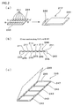
- FIG. 2 shows the configuration of the container 212 containing the artificial nail materials 211.
- a container main body 241 of the container 212 is, for example, in the shape of a flat, square body made of cardboard with a lid at the end that can be opened and closed, and which has a hole 242 formed therein for hanging from a hook for display in a shop.
- the container main body 241 contains a rectangular artificial nail material support base 243.
- Formed on the upper surface of the artificial nail material support base 243 are attachment surfaces 244 for the artificial nail materials 211, having a curved cross-section and spaced at fixed intervals.
- Each attachment surface 244 has an adhesive layer 245 that enables the artificial nail material 211 to be detachably attached thereto.
- each of the artificial nail printing shops 204 has collection holders 246.
- the collection holder 246 has a mount 247, a container section 248 for housing the artificial nail material support bases 243 formed on the surface thereof, and a lid 249 that covers the artificial nail support bases 243 housed in the container section 248.
- the collection holder 246 can hold a plurality of artificial nail support bases 243 to which artificial nails have been affixed after the nails have been printed with a design or the like; in the illustrated example, a collection holder 246 can hold four artificial nail support bases 243.
- the inkjet printer 1 has a media transport tray 7 that is conveyed through an inkjet head printing position. Formed on the upper surface of the media transport tray 7 is a carrier surface 74 for carrying the artificial nail support base 243. To position the artificial nail support base 243, a shallow recess 74a is formed in the carrier surface 74 into which the artificial nail support base 243 fits into place. The detailed configuration of the inkjet printer 1 is described later.
- the artificial nail material 211 is conventionally manufactured of molded resin.
- the artificial nail material 211 is removed from a molding machine, it is given an undercoating to form a water-based ink image receiving layer on the surface thereof.
- an air-gun 261 is used to apply the undercoating to the artificial nail material 211 that has been removed from the molding machine.
- each piece of the artificial nail material 211 is removed and adhered to each attachment surface of the artificial nail material support base 243.
- the undercoating can be applied after the artificial nail material 211 is removed.
- an artificial nail stand 262 is installed in a shop front of each of the artificial nail printing shops 204 on which are displayed containers 212 containing many types of artificial nail material.
- an artificial nail design book 263 showing the various designs and the like that can be printed on the artificial nails.
- a signboard 264 for showing new artificial nail designs.
- the artificial nail printing data corresponding to the designs shown in the artificial nail design book 263 is stored in RAM or external memory (not shown) of the personal computer 214 of the printing system201. There is also aplace for storing new designs.
- the artificial nail printing data can be selected via the keyboard 231 or by a touch of the touch-panel 232. That is, touch-panel touch-keys carry numbers and symbols corresponding to storage locations of the artificial nail printing data. These numbers and symbols are also assigned to the artificial nail designs in the artificial nail design book 263.
- a customer who comes to the artificial nail printing shop 204 selects the desired artificial nail material from the artificial nail stand 262; that is, she selects the container 212 containing artificial nail material of the desired shape and material.
- the customer also selects the desired printing data from the artificial nail design book 263. After making her selection, she goes to the shop counter 265, hands the selected container 212 to a shop assistant and tells the shop assistant the number of the selected printing data. After the shop assistant receives payment, the artificial nail material is printed.
- the artificial nail support base 243 with the adhered artificial nail material 211 is removed from the container 212 and placed in the positioning recess 74a formed in the carrier surface 74 of the media transport tray 7. Then, using the touch-panel 232 or keyboard 231, the printing data the customer wants is specified and the inkjet printer 1 is operated.
- the transporting of the media transport tray 7 carrying the artificial nail support base 243 starts, and as the artificial nail material 211 adhered to the artificial nail support base 243 carried on the media transport tray 7 passes through the printingposition, the selectedprinting data is printed in water-based ink on the surface (the surface on which the image receiving layer is formed) of each artificial nail material 211.
- the artificial nail support base 243 is removed from the media transport tray 7 and placed in a provided drier 266 to dry the printed surface.
- a commercial topcoat 267 is applied to provide a clear protective layer that protects the printed surface of the artificial nail material. After the topcoat has been applied, it is again placed in the drier 266 to dry the topcoat. As a result, artificial nails printed with the desired design are obtained which are handed to the customer.
- artificial nail printing data canbe received from the delivery center 202 on a regular basis or when required.
- the printing data from the delivery center 202 can also be delivered to a portable information terminal, such as a mobile telephone 268, for example, and downloaded from the portable information terminal to the personal computer 214 of the artificial nail printing shops 204 (see Figure 1).
- data on hand such as photographic data, for example, read by the scanner 219 can be used as printing data, or printing data stored on CD, DVD or FD or the like can be read in.
- image data from the digital camera 217 or video camera 218 can also be acquired as printing data.
- the present invention can be used for printing of other media.
- it can be applied in the same way to balls, tiles, bricks, stones, timepieces, rings and other personal accessories, and office products.
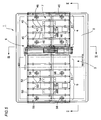
- Figure 5 is a plan view of the inkjet printer of this example
- Figure 6 is a side view along line II-II of Figure 5
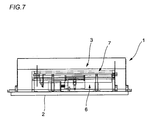
- Figure 7 is a cross-sectional view along line III-III of Figure 5.
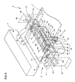
- the inkjet printer 1 of this example has a frame 2, an inkjet head unit 3 positioned substantially in the center of the upper surface thereof, a paper-feed-side flatbed (tray guide) 4 located on the paper-feed side of the head unit 3, a paper-delivery-side flatbed (tray guide) 5 located on the paper-delivery side of the head unit 3, and a tray transport unit 6 located between the head unit 3 and the delivery-side flatbed 5.
- the tray transport unit 6 By means of the tray transport unit 6, the media transport tray 7 is moved reciprocally along a transport path through a printing position 31 by the head unit 3.
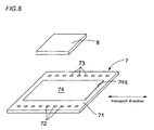
- Figure 8 is a perspective view of the media transport tray.
- the media transport tray 7 includes a square plate 71 of a set thickness, and a row of sprocket holes 72 and 73 formed along each edge thereof, in the transport direction.
- the region on the flat surface of the square plate 71 enclosed by a dotted line is the recording media carrier surface 74.
- Recording media 8 such as a thick wooden tablet, is placed on this carrier surface 74.
- FIGS 9 and 10 are perspective and side views of the tray transport unit 6.
- the tray transport unit 6 has a pair of sprockets 61 and 62 that can engage with the sprocket holes 72 and 73 along the edges of the media transport tray 7, a gap adjustment mechanism 10 that can move the sprockets 61 and 62 towards and away from a nozzle surface 33 (see Figure 6) of an inkjet head 32 of the head unit 3, and a drive transmission mechanism 9 that rotatably drives the pair of sprockets 61 and 62.
- the sprocket 61 comprises two gearwheels 63 and 64, a toothed belt 65 around the two gearwheels 63 and 64, and engaging projections 66 formed at regular intervals around the outer surface of the toothed belt 65.
- the toothed belt 65 forms a loop that is elongated in the direction in which the media transport tray is moved.
- the other sprocket 62 has a similar construction, comprising two gearwheels 67 and 68, a toothed belt 69, and engaging projections 70 formed at regular intervals around the outer surface of the toothed belt 69.
- the height of a media tray transport plane is defined by the upper horizontal outer surfaces of the toothed belts 65 and 69.
- the gap adjustment mechanism 10 includes a rotational shaft 11 on which the gearwheels 63 and 67 of the sprockets 61 and 62 are concentrically affixed, and a rotational shaft 12 on which the other gearwheels 64 and 68 of the sprockets 61 and 62 are concentrically affixed.
- These shafts 11 and 12 are rotatably maintained by a support plate 13.
- the support plate 13 includes a bottom portion 131 and side portions 132 and 133 that extend vertically up from both ends of the bottomportion 131.
- the shafts 11 and 12 are mounted horizontally and in parallel spanning the side portions 132 and 133, perpendicular to the travel direction.
- the center of the bottom portion 131 of the support plate 13 is supported by a lift member 14.
- the lift member 14 has sideplate portions 143 and 144 in which are formed horizontal openings 141 and 142 that can receive the bottom portion 131 from a horizontal direction, and a horizontal bottom portion 145 that connects the lower ends of the sideplate portions 143 and 144.
- a rotational shaft 145 extends horizontally across at the upper sides of the horizontal openings 141 and 142.
- Rotatably fixed to each end of the rotational shaft 145 are rotatable upper presser rollers 146 and 147.
- two rotational shafts 148 and 149 extend horizontally across at the lower sides of the horizontal openings 141 and 142.
- Rotatably fixed to each end of the rotational shafts 148 and 149 are rotatable lower presser rollers 151 and 152, and 153 and 154.
- the support plate bottom portion 131 When horizontally inserted into the horizontal openings 141 and 142 formed in the sideplate portions 143 and 144, the support plate bottom portion 131 is sandwiched vertically between the upper presser rollers 146 and 147 and the lower presser rollers 151 and 152, and 153 and 154. Therefore, the support plate 13 can slide horizontally while being moved vertically.
- the lift member 14 has an extension portion 155 that extends down from the sideplate portion 143 and is affixed to a vertical rack 16.
- a pinion 17 that engages with the rack 16 is fixed to the output shaft 181 of a stepping motor 18 used for raising and lowering.
- the rotational force of the motor is converted into vertical motion for raising and lowering the lift member 14.
- the support member 13 is also moved up or down, as well as the sprockets 61 and 62 affixed to the shafts 11 and 12 suspended by the support member 13.
- the gap between the plane of transport of the media transport tray defined by the sprockets 61 and 62 and the inkjet head 32 of the head unit 3 is increased or decreased accordingly.
- a follower gearwheel 19 is concentrically affixed to one end of the rotational shaft 11 on which the sprockets 61 and 62 are disposed.
- the follower gearwheel 19 is in engagement with a drive gearwheel 20 affixed to the frame 2.
- the drive gearwheel 20 is linked to the transport motor (not shown) via a speed-reduction gear train 21.
- the shafts 11 and 12 pass through the sideplate portions 132 and 133 and extend horizontally to the outside thereof.
- Located on the outside of the sideplate portions 132 and 133 are a guide plate 22 with curved slide openings 221 and 222, and a guide plate 23 with curved slide openings 231 and 232.
- the ends of the shafts 11 and 12 are slidably disposed through the curved slide openings 221 and 222, and 231 and 232.
- the follower gearwheel 19 moving up or down is in engagement with the drive gearwheel 20 that is fixed in position. Because the follower gearwheel is always in engagement with the drive gearwheel 20, the follower gearwheel 19 has to go up or down along a curved locus 19a having the rotation center 20a of the drive gearwheel 20 as its center.
- the shafts 11 and 12 are made to move slidably in the curved slide openings 221 and 222, and 231 and 232 along a curved locus 19a.
- the shafts 11 and 12 To slide the shafts 11 and 12 up and down in the curved slide openings, the shafts must also be moved horizontally along with their sliding motion.
- the support plate 13 on which the shafts 11 and 12 are maintained is horizontally slidably supported by the lift member 14 which has upper presser rollers 146 and 147 and lower presser rollers 151 and 152, and 153 and 154. Consequently, raising and lowering is possible with the follower gearwheel 19 maintaining engagement with the drive gearwheel 20.
- the up and down movement of the flatbeds 4 and 5 is linked to the up and down movement of the sprockets 61 and 62.
- the transport plane defined by the sprockets 61 and 62 is always located on the same flat plane as the transport plane of the media transport tray 7 formed by the flatbeds 4 and 5.
- the flatbeds 4 and 5 have tray guides 41 and 42, and 51 and 52 used to guide the media transport tray 7. They also have a plurality of rollers 43 and 53 that prescribe the transport plane of the media transport tray 7.
- the shafts 44 and 55 on which these rollers 43 and 53 are rotatably supported are supported on horizontal support frames 45 and 55, which by means of vertical linear guides 46 and 56, are supported in a way that allows them to move vertically.
- Attached to the horizontal support frames 45 and 55 are brackets 47 and 57 that extend downwards and to which racks 48 and 58 are perpendicularly attached.
- Pinions 50 and 60 affixed to the output shafts of bed lift motors 49 and 59 are engaged with the racks 48 and 58.
- the horizontal support frames 45 and 55 can be moved up or down.
- the tray transport plane defined by the sprockets 61 and 62 is always maintained at the same height as the tray transport plane defined by the flatbeds 4 and 5.
- the media transport tray 7 moves reciprocally through the printing position, it is possible to print each artificial nail material 211 attached to the artificial nail support base 243 constituting the recording media 8 carried by the media transport tray 7.
- the media transport tray 7 is moved by the sprockets 61 and 62, which enables heavy recording media to be transported more securely, compared to the usual friction-based transport mechanisms that use paper-feed rollers.
- the gap between the artificial nail material 211 and the nozzle surface 33 of the inkjet head 32 can be kept constant. This makes it possible to also print on thick material.
- this example includes flatbeds 4 and 5 located at each end in the transport direction that are raised and lowered as one unit with the sprockets 61 and 62.
- a long media transport tray 7 can also be transported by also using the flatbeds 4 and 5 to support the media transport tray 7.
- the above example related to a printer equipped with sprockets that engage to move the media transport tray.
- the invention can, however, use friction rollers as transport members.
- the gap between the media transport tray and the print head, as defined by the rollers can be adjusted by using the lift mechanism to support the rollers.
- Print heads that can be used other than inkjet heads include thermal heads and wire-dot heads and the like.
- This invention can also be applied to ordinary printers that do not use media trays but transport rollers to transport the recording media.
- the transport rollers could be arranged to be movable towards or away from the print head.
- a print head 101 of a printer 100 could be attached to the printer body 103 in a way that allows the print head to be moved in a vertical direction.
- a sloping surface 104 is formed on the base 102 and a trapezoidal member 106 having a sloping surface 105 in close contact with the sloping surface 104 is affixed to the printer body 103 in a horizontally movable state.
- the print head 101 When a motor (not shown) is used to move the trapezoidal member 106 horizontally, the print head 101 is moved up or down by the sliding contact of the two sloping surfaces 104 and 105, thereby increasing or decreasing the gap between the print head 101 and the recording media. With such a configuration in which the print head is moved, the same effect could be obtained as in the case of the foregoing example.
- water-based ink is used to print on the surface of the artificial nail material.
- printing can be carried out using oil-based ink (solvent ink) instead of water-based ink.
- solvent ink instead of water-based ink.
- printing media such as artificial nail material or the like is carried by the inkjet printer media transport tray with the media loaded on the media support sheet.
- the media transport tray is moved through a position at which the loaded printing media is printed by the inkjet head.
- a water-based ink image receiving layer is formed on the surface of the printing media, making it possible to use print on various types of media using an inkjet printer.
Landscapes
- Ink Jet (AREA)
- Dot-Matrix Printers And Others (AREA)
Applications Claiming Priority (1)
| Application Number | Priority Date | Filing Date | Title |
|---|---|---|---|
| PCT/JP2002/008960 WO2004022345A1 (ja) | 2002-09-03 | 2002-09-03 | インクジェットプリンタを用いた印刷システム |
Publications (2)
| Publication Number | Publication Date |
|---|---|
| EP1535739A1 true EP1535739A1 (de) | 2005-06-01 |
| EP1535739A4 EP1535739A4 (de) | 2009-07-22 |
Family
ID=31972297
Family Applications (1)
| Application Number | Title | Priority Date | Filing Date |
|---|---|---|---|
| EP02762995A Withdrawn EP1535739A4 (de) | 2002-09-03 | 2002-09-03 | Einen tintenstrahldrucker verwendendes drucksystem |
Country Status (6)
| Country | Link |
|---|---|
| US (1) | US20050151818A1 (de) |
| EP (1) | EP1535739A4 (de) |
| CN (1) | CN100357100C (de) |
| AU (1) | AU2002328420A1 (de) |
| CA (1) | CA2496507A1 (de) |
| WO (1) | WO2004022345A1 (de) |
Families Citing this family (16)
| Publication number | Priority date | Publication date | Assignee | Title |
|---|---|---|---|---|
| JP4516355B2 (ja) * | 2004-05-21 | 2010-08-04 | 株式会社リコー | デザイン提供管理方法及びデザイン提供管理プログラム |
| KR100765334B1 (ko) * | 2006-09-19 | 2007-10-09 | 장성용 | 인조네일 제조방법 |
| JP2008230226A (ja) * | 2007-02-22 | 2008-10-02 | Seiko Epson Corp | インクジェットプリンタ |
| TWI331909B (en) * | 2007-12-18 | 2010-10-21 | Kinpo Elect Inc | Printing device and method using the same |
| US20120042794A1 (en) * | 2010-08-23 | 2012-02-23 | Tran Quoc N | Method and apparatus for using a flat bed printer for applying UV-sensitive ink to artificial fingernail tips |
| US8746820B2 (en) * | 2010-11-04 | 2014-06-10 | Casio Computer Co., Ltd. | Nail print apparatus and print controlling method |
| JP5402980B2 (ja) * | 2011-05-09 | 2014-01-29 | カシオ計算機株式会社 | ネイルプリント装置及びネイルプリント装置の印刷制御方法 |
| FR3009519B1 (fr) * | 2013-08-07 | 2015-10-30 | Ozongle | Systeme et procede d'impression pour appliquer un dessin sur au moins une surface d'ongle. |
| US20160295989A1 (en) * | 2014-01-09 | 2016-10-13 | Q-Tee Product Design, Llc | Artificial nails with displays |
| US20150189971A1 (en) * | 2014-01-09 | 2015-07-09 | Quadir Hakeem | Artificial nails with displays |
| JP6269349B2 (ja) * | 2014-06-30 | 2018-01-31 | カシオ計算機株式会社 | 描画装置及び描画装置の描画方法 |
| JP6504047B2 (ja) * | 2015-12-28 | 2019-04-24 | カシオ計算機株式会社 | 描画装置 |
| US10576588B2 (en) | 2017-09-05 | 2020-03-03 | S L Chasse Welding & Fabricating, Inc. | Fabrication layout device and method |
| CN110675557A (zh) * | 2019-09-24 | 2020-01-10 | 苏州苏丰机械科技有限公司 | 服装定制自动售货机及其工作方法 |
| JP7363409B2 (ja) * | 2019-11-25 | 2023-10-18 | 船井電機株式会社 | 印刷装置 |
| USD1002416S1 (en) | 2020-01-14 | 2023-10-24 | Donner Nicholas J | Marker device for use with a CNC layout table |
Family Cites Families (21)
| Publication number | Priority date | Publication date | Assignee | Title |
|---|---|---|---|---|
| US2979061A (en) * | 1957-08-02 | 1961-04-11 | Technical Tape Corp | Nail coverings and methods of making same |
| US4985842A (en) * | 1987-11-13 | 1991-01-15 | Ward Robert L | Dynamically variable display and printer subsystem for use in sorting operations |
| US4990004A (en) * | 1988-10-12 | 1991-02-05 | Brother Kogyo Kabushiki Kaisha | Printer having head gap adjusting device |
| US5309365A (en) * | 1992-07-02 | 1994-05-03 | Gerber Scientific Products, Inc. | System for cutting artificial nail tips and for decorating the same or existing nails using automated cutting processes |
| CA2110447C (en) * | 1992-12-03 | 2001-08-07 | Kazuyoshi Takahashi | Image output apparatus, image output method, ink jet print method and printed product obtained with said method |
| JP2880627B2 (ja) * | 1993-06-25 | 1999-04-12 | 東芝テック株式会社 | 印字ギャップ調整装置 |
| JP4322968B2 (ja) * | 1995-05-12 | 2009-09-02 | コニカミノルタホールディングス株式会社 | インクジェット布帛捺染装置及びインクジェット布帛捺染方法 |
| JPH09239968A (ja) * | 1996-03-06 | 1997-09-16 | Toray Ind Inc | プリント装置及びプリント製品の製造方法 |
| JPH09300599A (ja) * | 1996-05-13 | 1997-11-25 | Master Maindo:Kk | ケース入り記録媒体の印刷方法 |
| WO1999033372A1 (fr) * | 1997-12-24 | 1999-07-08 | Jit Ceremony Co., Ltd. | Procede et dispositif de decoration sur ongles |
| JP2000006384A (ja) * | 1998-06-25 | 2000-01-11 | Mitsumi Electric Co Ltd | 立体面に印刷できる印刷装置 |
| US6328949B1 (en) * | 1998-10-14 | 2001-12-11 | Dino Tessarolo | Nail covering system |
| JP4199866B2 (ja) * | 1998-10-21 | 2008-12-24 | 株式会社マスターマインド | プリンタ |
| US5931166A (en) * | 1998-12-22 | 1999-08-03 | Weber; Paul J. | Fingernail decorating |
| US6286517B1 (en) * | 1998-12-22 | 2001-09-11 | Pearl Technology Holdings, Llc | Fingernail and toenail decoration using ink jets |
| US6035860A (en) * | 1999-01-14 | 2000-03-14 | Belquette Ltd. | System and method for applying fingernail art |
| JP3070011B1 (ja) * | 1999-06-15 | 2000-07-24 | 株式会社アトラス | ネイルプリント方法及び装置 |
| JP3687426B2 (ja) * | 1999-07-23 | 2005-08-24 | セイコーエプソン株式会社 | 印刷補助具及びその組み立て治具並びに記録装置 |
| JP2002065346A (ja) * | 2000-08-29 | 2002-03-05 | General Kk | 付け爪用基材セットおよびこれを用いた付け爪 |
| JP2002165632A (ja) * | 2000-11-30 | 2002-06-11 | Matsushita Electric Works Ltd | ネイルアートプリンター |
| WO2004043200A1 (en) * | 2002-11-13 | 2004-05-27 | Miic America, Inc. | A system and process for creating custom fit artificial fingernails using a non-contact optical measuring device |
-
2002
- 2002-09-03 WO PCT/JP2002/008960 patent/WO2004022345A1/ja not_active Ceased
- 2002-09-03 US US10/503,663 patent/US20050151818A1/en not_active Abandoned
- 2002-09-03 EP EP02762995A patent/EP1535739A4/de not_active Withdrawn
- 2002-09-03 CA CA002496507A patent/CA2496507A1/en not_active Abandoned
- 2002-09-03 CN CNB028277872A patent/CN100357100C/zh not_active Expired - Fee Related
- 2002-09-03 AU AU2002328420A patent/AU2002328420A1/en not_active Abandoned
Also Published As
| Publication number | Publication date |
|---|---|
| CN100357100C (zh) | 2007-12-26 |
| US20050151818A1 (en) | 2005-07-14 |
| EP1535739A4 (de) | 2009-07-22 |
| HK1076616A1 (zh) | 2006-01-20 |
| AU2002328420A1 (en) | 2004-03-29 |
| WO2004022345A1 (ja) | 2004-03-18 |
| CN1617800A (zh) | 2005-05-18 |
| CA2496507A1 (en) | 2004-03-18 |
Similar Documents
| Publication | Publication Date | Title |
|---|---|---|
| US20050151818A1 (en) | Printing system using ink-jet printer | |
| US6302601B1 (en) | Substrate carrier and printhead mounting for printer | |
| US6148722A (en) | Compact disc and recordable compact disc thermal transfer printer | |
| WO1991000183A1 (en) | Apparatus for preparing data recording cards | |
| US20080216688A1 (en) | Inverted Reverse-Image Transfer Printing | |
| JP4943592B2 (ja) | インクジェットプリンタを用いた印刷システム | |
| US20080217842A1 (en) | Substrate Feeding in a Credential Production Device | |
| JP2520862B2 (ja) | 少なくとも2つの空間的に互いに分離された印刷ステ―ションを備えた印刷装置 | |
| EP2036733B1 (de) | Informationsaufzeichnungsvorrichtung | |
| JP2000190467A (ja) | プリンタ | |
| HK1076616B (en) | Printing system using ink-jet printer | |
| JP2009181636A (ja) | メディア処理装置 | |
| CN111070912B (zh) | 便携式热升华打印机的齿条装置 | |
| JP3701805B2 (ja) | インクジェットプリンタを用いた印刷方法 | |
| JP3891548B2 (ja) | 画像形成装置 | |
| JP4683786B2 (ja) | プリンタ | |
| US9180706B2 (en) | Cantilevered credential processing device component | |
| JP3752900B2 (ja) | カードリーダ | |
| JP2000190466A (ja) | ジグソ―パズルの製造方法 | |
| JP2004216590A (ja) | 記録装置 | |
| WO2000038925A1 (en) | Method of making jigsaw puzzle | |
| JP2009070459A (ja) | 搬送機構及びそれを備えた情報処理装置 | |
| JP2021080031A (ja) | カード供給装置及び記録装置 | |
| JP2003163773A (ja) | 画像形成装置 | |
| JP2004160893A (ja) | 熱転写プリンタ |
Legal Events
| Date | Code | Title | Description |
|---|---|---|---|
| PUAI | Public reference made under article 153(3) epc to a published international application that has entered the european phase |
Free format text: ORIGINAL CODE: 0009012 |
|
| 17P | Request for examination filed |
Effective date: 20040906 |
|
| AK | Designated contracting states |
Kind code of ref document: A1 Designated state(s): AT BE BG CH CY CZ DE DK EE ES FI FR GB GR IE IT LI LU MC NL PT SE SK TR |
|
| AX | Request for extension of the european patent |
Extension state: AL LT LV MK RO SI |
|
| RTI1 | Title (correction) |
Free format text: PRINTING SYSTEM USING INK-JET PRINTER |
|
| DAX | Request for extension of the european patent (deleted) | ||
| RBV | Designated contracting states (corrected) |
Designated state(s): FR IT |
|
| REG | Reference to a national code |
Ref country code: DE Ref legal event code: 8566 |
|
| A4 | Supplementary search report drawn up and despatched |
Effective date: 20090623 |
|
| STAA | Information on the status of an ep patent application or granted ep patent |
Free format text: STATUS: THE APPLICATION HAS BEEN WITHDRAWN |
|
| 18W | Application withdrawn |
Effective date: 20090901 |